1
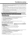
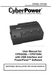
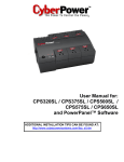
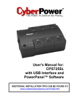
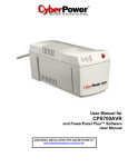
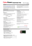
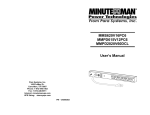
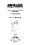
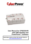
MN 325/MN 525
User’s Manual
TABLE OF CONTENTS
Safety Instructions....... ... .. ... ... ... ...1
Description……………………………..1
Determining Power Requirements…..2
Hardware Installation Guide………….2
Software Installation Guide…………..3
Software User Manual………………..4
Battery Replacement Instructions..... 8
LED Indicators………………………..10
Trouble Shooting Guide…………… .11
Specifications………………………. 12
Declaration of Conformity ………… .13
Warranty... ... ... ... ... ... ... ... ... ... . 14
Thank you for purchasing a MINUTEMAN UPS Product. To enjoy all the features and
benefits of this Uninterruptible Power Supply (UPS), please read and follow all
installation and operation instructions completely. This UPS is designed to provide
power protection for connected electronic equipment. The accompanying MINUTEMAN
PowerCenter software saves data, closes open applications and automatically shuts
down your computer system in an intelligent and orderly manner.
FCC Notice
This equipment has been tested and found to comply with the limits for a Class B Digital
Device, pursuant to Part 15 of the FCC Rules. These limits are designed to provide
reasonable protection against harmful interference in residential installation. This
equipment generates, uses and can radiate radio frequency energy and, if not installed
and used in accordance with the instructions, may cause harmful interference to radio
communications. However, there is no guarantee that interference will not occur in a
particular installation. If this equipment does cause harmful interference to radio or
television reception, which can be determined by turning the equipment off and on, the
user is encouraged to try to correct the interference by one or more of the following
measures: (1) Reorient or relocate the receiving antenna. (2) Increase the separation
between the equipment and receiver. (3) Connect the equipment into an outlet on a
circuit different from that to which the receiver is connected. (4) Consult the dealer or an
experienced radio/TV technician for help.
Any special accessories needed for
compliance must be specified in the instruction.
CAUTION: A shielded-type power cord is required in order to meet FCC emission limits
and to prevent interference to the nearby radio and television reception. It is essential
that only the supplied power cord be used. Use only shielded cables to connect I/O
devices to this equipment.
CAUTION: Any changes or modifications not expressly approved by the guarantee of
this device could void the user’s authority to operate the equipment.
MN 325/MN 525 User’s Manual
Uninterruptible Power Supply (UPS)
IMPORTANT SAFETY INSTRUCTIONS (SAVE THESE INSTRUCTIONS)
This manual contains important safety instructions. Please read and follow all instructions
carefully during installation and operation of UPS.
Read this manual thoroughly before attempting to
unpack, install, or operate.
CAUTION! To prevent the risk of fire or electric
shock, install in a temperature and humidity controlled indoor area, free of conductive contaminants. (Please see specifications for acceptable
temperature and humidity range).
CAUTION! To reduce the risk of electric shock,
do not remove the cover. Authorized Service
Personnel must perform repairs and maintenance. No user serviceable parts inside.
CAUTION! Hazardous live parts inside can be
energized by the battery even when the AC input
power is disconnected.
CAUTION! UPS must be connected to an AC
power outlet with fuse or circuit breaker protection. Do not plug into an AC wall outlet that is not
grounded. If you need to de-energize this equipment, turn off and unplug the UPS.
CAUTION! To avoid electrical shock, turn off the
UPS and unplug it from the AC power source
before servicing the battery or installing a computer component.
DO NOT USE FOR MEDICAL OR LIFE SUPPORT EQUIPMENT! MINUTEMAN UPS does
not sell products for life support or medical applications. DO NOT use in any circumstance that
would affect operation or safety of any life support equipment or with any medical applications
or patient care.
DO NOT USE WITH OR NEAR AQUARIUMS!
To reduce the risk of fire or electric shock, do not
use with or near an aquarium. Condensation
from the aquarium can cause the UPS to short
out.
DESCRIPTION
SWF Indicator (MN 525 Only)
The Site Wiring Fault (SWF) LED will illuminate to
warn the user that a wiring problem exists, such
as bad ground, missing ground or reversed wiring. If the SWF LED is illuminated, disconnect all
of the equipment from the UPS and have an
electrician check to ensure the AC wall outlet is
wired correctly.
Battery/Surge Outlets
Provides battery-powered/surge outlets for the
connected equipment and insures uninterrupted
operation of your equipment during a power
failure.
Circuit Breaker
Surge Only Outlets
Serial Port to PC
The circuit breaker provides overload and fault
protection. Under normal operating conditions,
the circuit breaker is depressed.
Provides surge protection for non-critical equip- This port allows connection and communication
ment.
from the DB-9 serial port on the computer to the
Power Switch
UPS. The UPS communicates its status to the
Can be used as a master on/off switch for equip- MINUTEMAN PowerCenter software. This interment connected to the battery-powered outlets.
face is also compatible with the UPS service
Power On Indicator
provided by Windows NT and Windows 2000.
This LED is illuminated when the utility condition RJ 11 Phone Jacks
is normal and the UPS outlets are providing Protects any standard modem, fax or single line
power, free of surges and spikes.
telephone.
1
INSPECTION
The package contents:
(1) MINUTEMAN PowerCenter software (floppy disk); (1) Serial interface cable (DB-9); (1) Telephone
cable; (1) User’s Manual; (1) Warranty registration card; (1) Platinum Protection Policy; (1) UPS.
HOW TO DETERMINE THE POWER REQUIREMENTS OF YOUR EQUIPMENT
1. Make sure that the total Volt-Amp (VA) requirements of your computer, monitor and peripheral
equipment does not exceed 1200VA for the MN 325 or 1440VA for the MN 525.
2. Ensure that the equipment plugged into the battery-powered outlets does not exceed the UPS’s
rated capacity. If UPS’s rated capacities are exceeded, an overload condition may occur and
cause the UPS to shut down and trip the circuit breaker.
3. If the power requirements of your equipment are listed in values other than Volt-Amps (VA),
convert Watts (W) or Amps (A) into VA by doing the calculations below. Note: The equation below only calculates the maximum amount of VA that the equipment can use, not what is typically
used by the equipment at any given time. Users should expect usage requirements to be approximately 60% of below value to estimate power requirements:
Watts (W) x 1.82 =
VA or
Amps (A) x 120 =
VA
Add the totals for all of the equipment and multiply this total by 0.6 to calculate actual requirements.
Note: Many factors can affect the amount of power that your computer system will require. The
total load that you will be placing on the battery-powered outlets should not exceed 80% of the
UPS’s capacity.
Hardware Installation Guide
1. Your new UPS may be used immediately upon
receipt. However, charging the battery for at
least 4-hours is recommended to ensure that
the battery’s maximum charge capacity is
achieved. Charge loss may occur during shipping and storage. To recharge the battery, plug
the power cord into the AC wall outlet and turn
the power switch on. Note: The MN 525 will
charge the battery with the power switch on or off.
2. If you wish to use the software, connect the enclosed serial interface cable to the serial port on the
UPS and an open serial port on the computer. If
you are not going to use the software, you do not
need to connect the cable.
3. With the UPS unit off and unplugged, connect your
computer, monitor, and any externally powered data storage device
(Zip drive, Jazz drive, Tape drive, etc…) into the battery power supplied outlets. Plug your peripheral equipment (printer, scanner,
speakers) into the full-time surge protection outlets. DO NOT plug a
laser printer, copier, space heater, vacuum or other large electrical device into the UPS. The power demands of these devices will overload and possibly damage the UPS.
4. To protect a fax, phone or modem, connect a telephone cable from
the wall jack outlet to the IN jack of the UPS. Connect a telephone
cable from the OUT jack to the modem port on your computer. The
OUT jack can be used to protect a telephone or fax machine.
2
MN 325/MN 525 User’s Manual
Uninterruptible Power Supply (UPS)
5. Plug the UPS into a 2 pole, 3 wire grounding receptacle (AC wall outlet). Make sure the wall
branch outlet is protected by a fuse or circuit breaker and does not service equipment with large
electrical demands (e.g. refrigerator, copier, etc…). Note: DO NOT use extension cords, power
or surge strips on the input or the output of the UPS.
6. Depress the power switch to turn the UPS on. The power on indicator light will illuminate and the
UPS will “beep” once.
7. If an overload is detected, an audible alarm will sound and the UPS will emit one long beep. To
correct this, turn the UPS off and unplug at least one piece of equipment from the batterypowered outlets. Wait 10-seconds. Make sure the circuit breaker is depressed and then turn the
UPS on.
8. Your UPS is equipped with an auto-charge feature (MN 525 only). When the UPS is plugged into
an AC wall outlet, the battery will automatically recharge.
9. To maintain optimal battery charge, leave the UPS plugged into an AC wall outlet with the power
switch turned on at all times.
10. To store your UPS for an extended period, cover and store it with the battery fully charged. Recharge the battery every three months to ensure battery life.
MINUTEMAN POWERCENTER SOFTWARE INSTALLATION GUIDE
Note: Use of the software is optional. The UPS will provide surge protection and battery backup
without the software. You must use the software if you wish to have the automatic shutdown feature.
FOR WINDOWS 95/98/Me
1. Turn the UPS off and unplug it.
2. Connect the serial interface cable to the UPS and an open serial port on the back of the computer. Note: You must use the serial cable that was provided with the UPS.
3. Plug the UPS into an AC wall outlet, turn the UPS on and then start your computer.
4. Click on Start, point to Settings, and then click Control Panel.
5. Double-click Add/Remove Programs.
6. Insert the software disk into the floppy drive.
7. Click Install.
8. Follow the on-screen instructions.
9. Once the software is installed, remove the floppy disk and restart your computer.
When your computer restarts, the MINUTESoftware Icon
MAN PowerCenter software will appear on
your screen for a few seconds, and then minimize. It will appear as a blue and white battery
icon located in the system tray, near the clock.
FOR WINDOWS NT
1.
2.
3.
4.
5.
6.
7.
8.
9.
10.
11.
12.
13.
14.
15.
16.
Click on Start, point to Settings, and then click Control Panel.
Double-click the UPS Icon.
Remove the check mark from the box labeled UPS is installed on.
Click OK.
Acknowledge the message that the UPS is in an unknown state.
Exit to the desktop.
Shutdown your computer.
Turn the UPS off and unplug it.
Connect the serial interface cable to the UPS and an open serial port on the back of your computer. Note: You must use the cable that was provided with the UPS.
Plug the UPS into an AC wall outlet, turn the UPS on and then start your computer.
Click on Start, point to Settings, and then click Control Panel.
Double-click Add/Remove Programs.
Insert the software disk into the floppy drive.
Click Install.
Follow the on-screen instructions.
Once the software is installed, remove the floppy disk and restart your computer.
3
When your computer restarts, the MINUTEMAN PowerCenter software will appear on
your screen for a few seconds, and then minimize. It will appear as a blue and white battery
icon located in the system tray, near the clock.
Software Icon
FOR WINDOWS 2000
1.
2.
3.
4.
5.
6.
7.
8.
Click on Start, point to Settings, and then click Control Panel.
Double-click on Power Options.
On the UPS Tab, click Select.
In the UPS Selection Dialog Box, under Manufacturers, click None.
Exit to the desktop.
Shutdown the computer.
Turn the UPS off and unplug it.
Connect the serial interface cable to the UPS and an open serial port on the back of your computer. Note: You must use the cable that was provided with the UPS.
9. Plug the UPS into an AC wall outlet, turn the UPS on and then start your computer.
10. Click on Start, point to Settings, and then click Control Panel.
11. Double-click Add/Remove Programs.
12. Insert the software disk into the floppy drive.
13. Click Install.
14. Follow the on-screen instructions.
15. Once the software is installed, remove the floppy disk and restart your computer.
When your computer restarts, the MINUTEMAN
PowerCenter software will appear on your
Software Icon
screen for a few seconds, and then minimize. It
will appear as a blue and white battery icon
located in the system tray, near the clock.
MINUTEMAN POWERCENTER SOFTWARE USER MANUAL
OVERVIEW
MINUTEMAN PowerCenter version 1.0 or greater is designed for use with Windows 95, Windows 98,
Windows Me, Windows NT and Windows 2000. The latest version will be available from
www.minutemanups.com. It works in conjunction with the UPS to provide full protection of valuable
computer systems, applications and data. In the event of a power failure, MINUTEMAN PowerCenter
automatically saves and closes open files under auto-assigned file names or existing files names
after a software controlled delay. The computer and UPS are automatically shutdown to conserve
battery power. Files with auto-assigned names will be saved under C:\PCTemp, where C is the
name of your main hard drive. Files that have previously been saved will be saved in their original
location.
MINUTEMAN PowerCenter is equipped with a Scheduled Shutdown feature which can automatically save and close open files and then shutdown the computer and UPS at a user specified date
and time. Use of this feature is optional and is not required for the power failure shutdown to occur.
The use of the MINUTEMAN PowerCenter software is optional. The UPS unit will provide full surge
protection and battery backup without the software. You must use the software if you wish to have
the automatic shutdown feature.
MINUTEMAN POWERCENTER MAIN WINDOW DESCRIPTION
1. Minimize Button: This button is
used to minimize the software.
2. Power Button:
Clicking on the
power button will stop the software.
3. Setup Button: Click the setup button to open the Setup Window.
4. Log Button: Click on the log button
to open the Log Window.
4
MN 325/MN 525 User’s Manual
Uninterruptible Power Supply (UPS)
5. Shutdown Button: Click the shutdown button to open the Scheduled Shutdown Window.
6. Battery OK Indicator: This indicator appears in a green color when AC power is normal and the
UPS and software are communicating.
7. AC Power Indicator: This indicator appears in a green color when AC power in normal. When
the power fails, the indicator will change to a red color with an “X” through it.
8. Scheduled Shutdown: If there is a shutdown scheduled within seven days, the information will
be displayed here. The user can schedule a shutdown in the Scheduled Shutdown Window.
9. Final Countdown: When the final countdown timer reaches zero, the software will begin shutting down the system. This can be adjusted in the Setup Window.
MINUTEMAN POWERCENTER SETUP WINDOW
1. Delay Between Warning Messages: This setting determines the
delay between the audible alarms.
2. Time Between Power Failure and
Initial Warning: This setting determines the delay between when
the power fails and the first audible
alarm.
3. Time Between Power Failure and
Shutdown Process: This user adjustable setting determines how long the UPS will run on battery before starting to shut down the system. If this is not checked, the UPS will run on battery
until the low battery condition occurs (approximately 2-minutes of backup time remaining), and
then, start the shutdown process. If the low battery condition occurs before this timer reaches
zero, the software will start the shutdown process.
4. UPS is Installed On: This shows the current COM port that the UPS is using. The port assigned
to the UPS needs to be used exclusively for the MINUTEMAN PowerCenter software.
5. OK Button: This button is used to exit the setup window and save any changes.
6. Cancel Button: This button is used to exit the setup window without saving any changes.
7. About Button: This button will display information about the software as well as contact information.
MINUTEMAN POWERCENTER LOG WINDOW
1. Display Window:
This area displays
either the Event Log or the Closed Application Information.
2. Event Log: Select this option to view
MINUTEMAN PowerCenter events such as
program start, program end, power failure
and low battery.
3. Closed Application Information: Select
this option to view the file names of applications that were saved by the MINUTEMAN PowerCenter software. Note: If an application has
an existing file name, it will be saved under that file name and not appear in this window.
4. OK Button: This button is used to exit the window.
5. Clear Button: This button is used to clear the information in the selected log.
5
MINUTEMAN POWERCENTER SHUTDOWN WINDOW
1. Display Window: Any schedule information will be displayed here.
2. Special Setting: This option is used to
schedule a shutdown at a specific date
and time.
3. Weekly Setting: This option is used to
schedule a shutdown for a specific time
and day of the week.
4. OK Button: This button is used to exit
the window.
5. Add Button: This button is used to add
an item to the schedule.
6. Clear Button: This button is used to delete the selected item.
7. Cancel Shutdown: This button is used to cancel the current shutdown.
8. Day, Date and Time: This is the area where you select the day, date and time that you want the
shutdown to occur. Once you have selected it, click the Add Button to add the item to the
schedule.
Note: The use of the schedule is optional and will have no effect on the shutdown of your system
during a power failure. This feature is simply used if you want to have your computer automatically shut down at a scheduled time.
USING THE WINDOWS NT UPS SERVICE
If you are running Windows NT, you may choose to use the Windows NT service instead of the
MINUTEMAN PowerCenter. You can run either MINUTEMAN PowerCenter or the NT service, but
not both.
To Configure the Windows NT UPS Service:
1. Click on Start, point to Settings, then Control Panel.
2. Double-click the UPS Icon.
3. Select the COM port that the UPS is connected to.
4. Set the Power Failure Signal to Negative.
5. Set the Low Battery Signal to Negative.
6. Set the Remote UPS Shutdown Signal to Positive.
7. Click OK.
Note: This service must be stopped in order to use the MINUTEMAN PowerCenter software. To
stop the service, remove the checkmark from Uninterruptible Power Supply is installed on. Click
OK. Acknowledge the message that the UPS is in an unknown state and exit to the desktop.
USING THE WINDOWS 2000 UPS SERVICE
If you are running Windows 2000, you may choose to run the Windows 2000 UPS service instead of
the MINUTEMAN PowerCenter. You can run either MINUTEMAN PowerCenter or the Windows
2000 UPS service, but not both.
To Configure the Windows 2000 UPS Service:
1. Click on Start, point to Settings, then Control Panel.
2. Double-click on Power Options.
3. On the UPS Tab, click Select.
4. In the UPS Selection Dialog Box, under Select Manufacturer, select Generic.
5. Under Select Model, select Custom.
6. On the UPS Tab, click Configure.
7. Set Power Fail/On Battery to Negative.
8. Set Low Battery to Negative.
9. Set UPS Shutdown to Positive.
10. Click OK.
Note: This service must be stopped in order to run the MINUTEMAN PowerCenter. To disable the
service, set the Manufacturer to None.
6
MN 325/MN 525 User’s Manual
Uninterruptible Power Supply (UPS)
Note: You must be logged on as an administrator or a member of the administrator’s group to make
these changes. Network policies may also prevent you from making these changes. Please contact
your network administrator for further assistance.
TESTING YOUR UPS SYSTEM
Once you have set up your UPS system, you may wish to test it. Make sure that the UPS has been
charged for at least 4-hours before performing this test.
If you are using the MINUTEMAN PowerCenter:
1.
With your UPS and computer on, open an application such as notepad.
2.
Enter some data into the application.
3.
Unplug the UPS from the AC wall outlet.
When a power failure occurs, the MINUTEMAN PowerCenter will appear on the screen. The outlet
and battery symbols will change to indicate a power failure. The countdown timer will move towards
zero. When the timer reaches zero, the software will begin to save and close any open applications.
The software will auto-assign names to any files that have not been previously saved, and then save
the file to the PCTemp folder which is located in the root directory of your C drive (where C is the
name of your main hard drive). Once, all open files have been saved and closed the MINUTEMAN
PowerCenter will shutdown the operating system. Once the operating system is shutdown, the UPS
will turn off within 90-seconds. Wait until the UPS has turned off before plugging the UPS back into
the AC wall outlet.
Once, the test has been completed, plug the UPS back into the AC wall outlet and turn it back on.
You may then restart your computer. Please allow 4-hours for the UPS to recharge before attempting
another self-test.
If you are NOT using the MINUTEMAN PowerCenter:
1.
Have your computer and UPS turned on.
2.
Unplug the UPS from the AC wall outlet to simulate a power failure.
3.
The UPS will begin beeping, indicating a power failure.
4.
Save and close any open files.
5.
Shut down the operating system.
6.
Once the computer system is shutdown, turn the UPS off.
As the battery discharges, the unit will beep more rapidly, indicating that the battery is nearing discharge. Once the test is complete, plug the UPS back in and start your computer. Please allow 4hours for the UPS to recharge before attempting another self-test.
7
REPLACING THE BATTERY (Authorized Service Personnel)
CAUTION! Read and follow the IMPORTANT SAFETY INSTRUCTIONS before servicing the battery. Service the battery under the supervision of Authorized Service Personnel knowledgeable of
batteries and their precautions.
CAUTION! Use only the specified type of battery. See your dealer for replacement batteries.
CAUTION! The battery may present risk of electrical shock. Do not dispose of battery in a fire, as it
may explode. Follow all local ordinances regarding proper disposal of batteries.
CAUTION! Do not open or mutilate the batteries. Released electrolyte is harmful to skin and eyes
and may be toxic.
CAUTION! Although the battery system voltage is only 12VDC, the battery can present a high risk of
short circuit current and electrical shock. The short circuit current capability of the battery is sufficient
to burn wire or tools very rapidly producing molten metal. Observe these precautions when replacing
the battery:
1. Remove all watches, rings or other metal objects.
2. Only use tools with insulated handles.
3. Do not lay tools or metal parts on top of battery or any terminals.
4. Wear protective eye gear (goggles), rubber gloves and boots.
5. Disconnect the charging source before connecting or disconnecting the battery terminals.
6. Determine if the battery is inadvertently grounded. If inadvertently grounded, remove the source
of ground. Contact with a grounded battery can result in electrical shock! The likelihood of such
shock will be reduced if; such grounds are removed during installation and maintenance (applicable to a UPS and a remote battery supply not having a grounded circuit).
BATTERY REPLACEMENT PROCEDURE
1.
2.
3.
4.
5.
Turn off and unplug all connected equipment.
Turn the UPS off and unplug the UPS’s power cord from the AC wall outlet.
Turn the UPS upside down.
Remove the retaining screws from the battery compartment door.
Remove the battery compartment door.
MN 325
Retaining Screws
8
MN 325/MN 525 User’s Manual
Uninterruptible Power Supply (UPS)
BATTERY REPLACEMENT PROCEDURE
MN 525
Retaining Screws
6.
7.
8.
9.
10.
11.
12.
Disconnect the battery positive (red) wire from the battery positive (+) terminal.
Turn the power switch on, to discharge the UPS.
Disconnect the battery negative (black) wire from the battery negative (-) terminal.
Remove the defective battery from the battery compartment.
Install the new battery into the battery compartment.
Reconnect the battery negative (black) wire to the battery negative (-) terminal.
Reconnect the battery positive (red) wire to the battery positive (+) terminal. Note: Some sparking may occur, this is normal.
13. Reinstall the battery compartment door and the retaining screws.
14. Charge the UPS for 4 to 8 hours to ensure the UPS performs expected runtime.
Note: Batteries are consider HAZARDOUS WASTE and must be disposed of properly at an appropriate recycling facility or return them to the supplier in the packing material for the new battery. Contact your local government for more information about proper disposal and recycling of
batteries.
Note: Replace the batteries with the same number and type as originally installed in the UPS.
These batteries have pressure-operated vents. These UPS contain sealed non-spillable lead-acid
batteries.
Model #
Battery
Model #
Battery
Part #
MN 325
12V3ah
MN 525
12V7ah
BP3-12
BP7-12
9
DEFINITIONS FOR ILLUMINATED LED INDICATORS
CONDITION
Power
ON
Site
Wiring
Fault
Circuit
Breaker
Alarm
On
Off
Set
Off
Off
On/Off
Set
Two
Beeps
Utility Failure- the UPS is in the battery
mode.
Off
On/Off
Set
Rapid
Beeps
Utility Failure- The UPS is in the battery
mode and will run out of battery-power shortly.
Up
Two
Beeps
or
Rapid
Beeps
System Overload- Occurs when connected
equipment exceeds the rating of UPS. Turn
the UPS off, unplug at least one piece of
equipment, wait 10-seconds, reset the circuit
breaker and turn the UPS on.
Set
Long
Beep
Battery Overload- Occurs when connected
equipment exceeds the rating of batterypowered outlets of the UPS. Turn the UPS off,
unplug at least one piece of equipment from
battery-powered outlets, wait 10-seconds,
reset the circuit breaker and turn the UPS on.
None
Site Wiring Fault (MN 525 Only)- This indicates a wiring problem with the AC wall outlet
such as bad ground, missing ground, or reversed wiring. Disconnect all electrical equipment from the UPS’s outlets and have an
electrician check the AC wall outlet to ensure
proper wiring.
Off
Off
On/Off
Off
On/Off
On
Set
Normal Mode
10
MN 325/MN 525 User’s Manual
Uninterruptible Power Supply (UPS)
TROUBLE SHOOTING
Problem
Possible Cause
Solution
Full-time
surge protection outlets
stop providing power to
equipment.
The UPS
does not
perform expected runtime.
Circuit breaker has
tripped due to an
overload.
Turn the UPS off and unplug at least one
piece of equipment. Wait 10-seconds,
reset the circuit breaker by depressing the
button, and then turn the UPS on.
Battery not fully
charged.
The Battery is defective.
Recharge the battery for at least 4-hours.
The UPS will
not turn on.
The on/off switch is
designed to prevent
damage by rapidly
turning it off and on.
The UPS is not
plugged into an AC
wall outlet.
The battery is defective.
Mechanical problem.
MINUTEMAN
PowerCenter
Software is
inactive (all
icons are
gray).
The serial cable is not
connected.
The serial cable is
connected to the
wrong serial port.
The UPS is not providing battery power.
The serial cable is not
the cable that was
included with the
UPS.
Contact MINUTEMAN UPS about replacement batteries at
[email protected]
Turn the UPS off. Wait 10-seconds and
then turn the UPS on.
Connect the UPS to an 110/120V 60Hz AC
wall outlet.
Contact MINUTEMAN UPS about replacement batteries at
[email protected]
Contact MINUTEMAN UPS at
[email protected]
Connect the serial cable to the UPS unit
and an open serial port on the back of the
computer. You must use the cable that
came with the UPS.
Connect the serial cable to the correct
serial port on the computer.
Shutdown your computer and turn the UPS
off. Wait 10-seconds and turn the UPS
back on. This should reset the UPS.
You must use the serial cable that was
included with the UPS for the software to
be able to communicate.
11
SPECIFICATIONS
Model number
VA/Watt rating
Input Voltage (AC Mode)
Input Frequency
Output Voltage (AC
Mode)
Output Voltage (Battery
Mode)
Output Frequency
(Battery Mode)
Transfer Time
Max. Load for batterypowered Outlets
Max. Combined load for
Surge Only and batterypowered Outlets
Output Wave Form
(Battery Mode)
Input Protection
Surge energy rating (one
time, 10/1000uS waveform)
Noise Filter
Protection
Operating Temperature
Operating Relative
Humidity
Net Size (Length x Width
x Height)
Net Weight
Typical Battery Recharge Time
Typical Battery Life
Battery
Battery Type
Safety Approvals
Expected Runtime in Minutes
Desktop PC with 15”
Monitor
Desktop PC with 17”
Monitor
Desktop PC with 21”
Monitor
MN 325
325VA/185W
MN 525
525VA/275W
100VAC to 140VAC
57 Hz to 63 Hz
100VAC to 140VAC
120VAC ± 5%
60Hz ±1Hz unless synchronized to utility
4ms Typical
325VA
185W
525VA
275W
10Amps
12Amps
Simulated Sine Wave
Resettable circuit breaker
500 Joules
Normal and common mode EMI/RFI suppression
Over current, short circuit protected, and latching shutdown
+ 32°F to 95° F. (0° C to 35° C)
0 to 95% NON-CONDENSING
9.88” x 5.06” x 3.25”
(25.1cm x 12.86cm x 8.26cm)
7.4 lbs (3.36Kg)
10.13” x 6.56” x 3.32”
(25.8cm x 16.67cm x 8.44cm)
13 lbs (5.9Kg)
8 hours typical from total discharge
3 to 6 years, depending on number of discharge/recharge cycles
12V3ah
12V7ah
Sealed, Non-spillable, Maintenance-free, Lead-acid
UL1778 (UPS), CUL107.1/FCC/DoC Class B
6–9
10 – 14
4–6
8 – 12
Not advised
(Under 1 Minute)
6 - 10
12
MN 325/MN 525 User’s Manual
Uninterruptible Power Supply (UPS)
DECLARATION OF CONFORMITY
Application of Council Directive(s): UL-1778
Standard(s) to which Conformity is declared: FCC CLASS B
Manufacturer’s Name: Para Systems, Inc. (MINUTEMAN UPS)
Manufacturer’s Address: 1455 LeMay Drive; Carrollton, Texas 75007 USA
Type of Equipment: Uninterruptible Power Supplies (UPS)
Model No: MN 325, MN 525
Year of Manufacturer: Beginning February 28, 2003
I, the undersigned, hereby declare that the equipment specified above conforms to the above
Directive(s).
Robert Calhoun
(Name)
Robert Calhoun
Manager Engineering
(Title)
February 28, 2003
(Date)
(Signature)
Carrollton, Texas, USA
(Place)
13
Limited Product Warranty
Para Systems Inc. (Para Systems) warrants this equipment, when properly applied and operated
within specified conditions, against faulty materials (excluding the Batteries) or workmanship for a
period of three years from the date of purchase. Para Systems Inc. (Para Systems) warrants the
Batteries for a period of two years from the date of purchase. For equipment sites within the United
States and Canada, this warranty covers repair or replacement of defective equipment at the discretion of Para Systems. Repair will be from the nearest authorized service center. Replacement parts
and warranty labor will be borne by Para Systems. For equipment located outside of the United
States and Canada, Para Systems only covers faulty parts. Para Systems products repaired or
replaced pursuant to this warranty shall be warranted for the unexpired portion of the warranty applying to the original product. This warranty applies only to the original purchaser who must have properly registered the product within 10 days of purchase.
The warranty shall be void if (a) the equipment is damaged by the customer, is improperly used, is
subjected to an adverse operating environment, or is operated outside the limits of its electrical specifications; (b) the equipment is repaired or modified by anyone other than Para Systems or Para Systems-approved personnel; or (c) has been used in a manner contrary to the product’s User's Manual
or other written instructions.
Any technical advice furnished before or after delivery in regard to use or application of Para Systems’s equipment is furnished without charge and on the basis that it represents Para Systems’s best
judgment under the circumstances, but it is used at the recipient’s sole risk.
Except as provided herein, Para Systems makes no warranties, expressed or implied, including
warranties of merchantability and fitness for a particular purpose. Some states do not permit limitation of implied warranties; therefore, the aforesaid limitation(s) may not apply to the purchaser.
EXCEPT AS PROVIDED ABOVE, IN NO EVENT WILL PARA SYSTEMS BE LIABLE FOR DIRECT,
INDIRECT, SPECIAL, INCIDENTAL, OR CONSEQUENTIAL DAMAGES ARISING OUT OF THE
USE OF THIS PRODUCT, EVEN IF ADVISED OF THE POSSIBILITY OF SUCH DAMAGE. Specifically, Para Systems is not liable for any costs, such as lost profits or revenue, loss of equipment, loss
of use of equipment, loss of software, loss of data, cost of substitutes, claims by third parties, or
otherwise. The sole and exclusive remedy for breach of any warranty, expressed or implied,
concerning Para Systems’s products and the only obligation of Para Systems hereunder, shall be the
repair or replacement of defective equipment, components, or parts; or, at Para Systems’s option,
refund of the purchase price or substitution with an equivalent replacement product. This warranty
gives you specific legal rights and you may have other rights, which vary from state to state.
Longer term and F.O.B. job site warranties are available at extra cost. Contact Para Systems (1-972446-7363) for details.
14
For more information, contact us at:
MINUTEMAN UPS / Para Systems, Inc.
1455 LeMay Drive
Carrollton, Texas 75007
Tel: (972) 446-7363
Fax: (972) 446-9011
Email: [email protected]
Web: www.minutemanups.com
UPS Sizing: www.sizemyups.com
Entire contents copyright ©2002 MINUTEMAN UPS / Para Systems, Inc.
All rights reserved. Reproduction in whole or in part without permission is prohibited.
PN: 34000224 Rev0
MN 325/MN 525 User’s Manual
Uninterruptible Power Supply (UPS)
Addendum
Installing PowerCenter on Windows XP (Home and Professional)
1) Click on Start and then click on Control Panel.
2) Double-click on Power Options then click on the UPS tab.
3) Set the manufacturer to None.
4) Exit to the desktop and shutdown your computer.
5) Turn the UPS off and unplug it.
6) Connect the serial interface cable to serial port on the UPS and an
open serial port on the back of the computer. (Note: You must
use the serial cable that was supplied with the unit).
7) Plug the UPS into an AC outlet, turn the UPS on and start your
computer.
8) Windows will find new hardware.
9) Insert the PowerCenter software disk into the floppy drive.
10) Follow the on-screen instructions
When the installation is completed, remove the floppy disk.
15