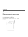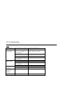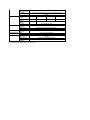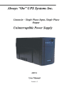
1
UPS
Uninterruptible Power System
Line Interactive UPS 325A/425A/525A/625A
Line Interactive Network UPS 425AP/525AP/625AP
USER‘S MANUAL
Important safety instructions
__________________________________________________________
_____
Thank you for selecting this uninterruptible power system (UPS). It provides
you with better protection for connected equipment.
Please read this manual!
This manual provides safety, installation and operating instructions that will
help you derive the fullest performance and service life that the UPS has to
offer.
Please save this manual!
It includes important instructions for the safe use of this UPS and for obtaining
factory service should the proper operation of the UPS come into question.
Please save or recycle the packaging materials!
The UPS‘s shipping materials were designing with great care to provide
protection from transportation related damage. These materials are invaluable if
you ever have to return the UPS for service. Damage sustained during transit is
not covered under the warranty.
Table of contents
__________________________________________________________
____
1 . I n t r o d u c t i o n……… ……… ………… ……… …..1
2.
Safety ………… …………… ………… ………… 2
3. Presentation
Front Panel.…………………………………3
Rear Panel.………… …………… ………….4
4. Installation………………….………………….5
5. Operation……………………………………….7
6. Alarms………………………….……………….8
7. Software Options……………………………9
8 . C o m p u t e r I n t e r f a c e P o r t… … … … … … … . . 1 0
9 . B a t t e r y r e p l a c e m e n t… … … … … … … ..… . 1 1
1 0 . T r o u b l e s h o o t i n g …… …… …… …… .. …… 1 2
11. Storage……………………………….……..12
12. Specifications … … … … … … …… … … … ..13
13. 中文裝機步驟…… … …… … … …… … …… .14
14. UPS測試方法… … … … … … … … … … … … ..15
15. 面板功能 …… …… ……… …… ……… …… .16
16. 軟體安裝 ……… ……… …… ……… ……… .17
1. INTRODUCTION
__________________________________________________________
_____
The product is line interactive UPS with the newest technology and powerful
function. The LINE INTERACTIVE ups is with AVR function allows input voltage
range from 75% to 125%, including on line voltage boost-up & buck down. An
ideal protection equipment for critical connected loads. It is based on
microprocessor controls, with utility power connected, the charging is ongoing,
no need to switch ON the UPS and at back-up mode, UPS can be
automatically turned OFF if none of the connected loads is operating to save
the battery energy. The indicator will be ON when battery needs replacement
and a cyclic self-testing function is included in order to verify both the operation
of the UPS and the condition of the battery.
In addition, This UPS provides advanced single telephone line or modem surge
suppression through the modular connectors on the back panel.
The LINE INTERACTIVE UPS and UPSMON monitoring software (optional kits)
makes your computer operate intelligent and provides you with the ability of
perfect protection of your critical devices.
Note: There is no guarantee that interference to radio/TV will not occur in
a particular installation. If this UPS causes interference to radio or
television reception, which can be determined by turning the UPS off and
on, the user is encouraged to try to correct the interference by one or
more of following measures:
●connect the equipment to an outlet on a circuit different from that to
which the receiver is connected
●increase the separation between the equipment and the receiver
●reorient the receiving antenna
2. Safety
__________________________________________________________
_____
CAUTION !
●To reduce the risk of electric shock, disconnect the UPS from the mains
supply before installing a computer interface signal cable. Reconnect the
power cord only after signaling interconnections have been made.
●The internal energy source(the battery) cannot be de-energized by the
user. The output may be energized when the unit is not connected to a
mains supply.
●The right way to de-energize the UPS properly in an emergency is to
move the I/O switch to the OFF position and disconnect the power cord
from the mains supply.
● The socket-outlet shall be installed near the equipment and easily
accessible.
●
Attention, hazardous through electric shock. Also with disconnection of
this unit the main, hazardous voltage still may be accessible through
supply from battery. The battery supply should be therefore disconnected
in the plus and minus pole when maintenance of service work inside the
UPS is considered.
●Do not dispose of batteries in a fire, the battery may explore.
●Do not open or mutilate the battery, released electrolyte is harmful to the
skin and eyes.
●A battery can present a risk of electric shock and high short circuit
current. The following precaution should be observed when working on
batteries
- Remove watches, rings or other metal objects.
- Use tools with insulated handles.
Caution: Risk of electric shock - hazardous live parts inside this unit are
energized from the battery supply even when the input AC power is
connected.
Caution: Risk of electric shock, do not remove cover. No user serviceable
parts inside, Refer servicing to qualified service personnel.
Warning: To reduce the risk of fire, replace only with the same type and
rating of fuse.
Warning: To reduce the risk of fire or electric shock, install in
temperature and humidity controlled indoor area of conductive
contaminants.
3. Presentation
__________________________________________________________
____
FRONT PANEL
3.1 "REPLACE BATTERY" indicator (RED LED)
The LED illuminates when the UPS's battery is no longer useful and must be
replaced.
Note: When replace battery, disconnect the utility power then open the
case and take notice of the battery's polarity while install the new battery
to avoid short.
3.2 "BACK UP" indicator (YELLOW LED)
The LED illuminates when the UPS is supplying battery power to the loads.
3.3 "LINE NORMAL" indicator (GREEN LED)
The LED illuminates when the line input voltage is normal.
3.4 "ON/OFF/TEST/SILENCE" button
Press the button more than 3 seconds to turn the UPS on or off, press the
button less than 1 second to activate the UPS's self-testing or silence the
back up alarm.
__________________________________________________________
__
REAR PANEL
3.5 COMPUTER INTERFACE (425AP/525AP/625AP models only)
Provide both RS-232 and relay signal to support NOVELL, UNIX, DOS,
WINDOWS and other operating systems.
3.6 OUTPUT POWER RECEPTACLES
3.7 AC INPUT POWER RECEPTACLE
3.8 TEL./MODEM SURGE PROTECTION
(425AP/525AP/625AP models only)
Surge protection for telephone and modem line to have the complete safety
connection for INTERNET service.
4. Installation
__________________________________________________________
____
4.0 Inspection
Inspect the UPS upon receipt. The packaging is recyclable; save it for reuse or
dispose of it properly.
4.1 Placement
Install the UPS in a protected area with adequate air flow and free of excessive
dust. Do not operate the UPS where the temperature and humidity is outside
the specified limits.
4.2 Connect Computer Interface (425AP/525AP/625AP models only)
UPSMON (or other power management software) and an interface kits can be
used
with this UPS. Use only kits supplied or approved by the manufacturer.
If used, connect the interface cable to the 9 pin computer interface port on the
back panel of the UPS.
Note: Computer interface connection is optional. The UPS works
properly without a computer interface connection.
4.3 Connect to Utility
Connect the AC input power connector to utility power to power up the UPS.
4.4 Charge the battery
The UPS charges its battery whenever it is connected to utility power. For best
results, charge the battery for 4 hours in the initial use.
4.5 Connect the loads
Plug the loads into the output connectors on the rear of the UPS. To use the
UPS as
a master on/off switch, make sure all of the loads are switched on.
Caution: Never connect a laser printer or plotter to the UPS with other
computer equipment. A laser printer or plotter periodically draws
significantly more power than when idle, and may overload the UPS.
4.6 Connect the telephone/modem lines
(425AP/525AP/625AP models only)
Connect a single line telephone or a modem line into the telephone/modem
surge protection sockets on the back of the UPS. The RJ-45/RJ-11 modular
sockets accept standard single line telephone connections. This connection
will require another length of telephone cable (supplied).
Note: This connection is optional. It is not necessary to use this UPS.
Caution: The telephone line current limiting feature could be rendered
inoperable if improperly installed. Make sure that the telephone line from
the wall is plugged into the connector marked “IN”, and the device to be
protected (telephone, modem, etc.) is plugged into the connector marked
“OUT”.
Caution: This surge protection device is for indoor use only and never
install telephone wiring during a lightning storm.
5. Operation
__________________________________________________________
____
5.1 Switch on
With the UPS plugged in, press and hold the on/off/test/silence button more
than 1 second until "LINE NORMAL" LED lit to switch the ups on. The UPS
will perform self-testing each time when it is switched on.
Note: When switched off the UPS maintains the battery charge and will
respond to commands received through the computer interface port.
5.2 Switch off
By pressing and hold the on/off/test/silence button more than 3 seconds until
the "LINE NORMAL" or "BACK UP" LED off.
5.3 SELF-TEST
Use the self-test to verify both the operation of the UPS and the condition of
the battery. In normal utility power, push the on/off/test/silence button less
than 1 second and UPS performs a self-test function. During the self-test, the
UPS operates a back up mode.
Note: During the self-test, the UPS briefly operates the loads on-battery
(the on-battery LED comes on).
If the UPS passes the self-test, it returns to on-line operation. The onbattery LED does off and the on-line LED goes on steady.
If the UPS fails the self-test it immediately returns to on-line operation and
lights the replace battery LED. The loads are not affected. Recharge the
battery overnight and perform the self-test again. If the replace battery
LED is still on, ask our nearest dealer to replace battery.
5.4 SILENCE
In "BACK UP" mode, push on/off/test/silence less than 1 second to silence the
audible alarm. (The function is void when under condition of "LOW BATTERY"
or "OVERLOAD")
Note: At back-up mode, UPS can be automatically turned off if none of
the connected loads is operating.
6. Alarm
__________________________________________________________
_____
6.1 "BACK UP" (slow alarm)
When in BACK UP mode, the YELLOW LED illuminates and the UPS sounds
an audible alarm. The alarm stops when the UPS returns to LINE NORMAL
operation.
Press the on/off/test/silence button during on-battery alarms to stop the
beeping.
6.2 "LOW BATTERY" (rapid alarm)
In BACK UP mode, when the battery energy runs low, the UPS beeps rapidly
until the UPS shuts down from battery exhaustion or returns to LINE NORMAL
operation.
6.3 "OVERLOAD" (continuous alarm)
When the UPS is overloaded (the connected loads exceed the maximum rated
capacity) the UPS emits continuous alarm to warn a overload condition.
Disconnect nonessential load equipment from UPS to eliminate the overload.
7. Software options
__________________________________________________________
____
7.1 UPSMON Software
The UPSMON software is applied standard RS-232 interface to perform
monitoring functions, and then provides an orderly shutdown of a computer in
the event of power failure. Moreover, UPSMON displays all the diagnostic
symptoms on monitor, such as Voltage, Frequency, Battery level and so on..
The software is available for DOS, Windows 3.1x, Windows 95 & Windows NT
V3.5 or later.
7.2 Interface Kits
A series of interface kits is available for operation systems that provide UPS
monitoring. Each interface kit includes the special interface cable required to
convert status signals from the UPS into signals which individual operating
system recognize. The interface cable at UPS side must be connected to
REMOTE PORT , at computer side can be either COM 1 or COM 2. The other
installation instructions and powerful features please refer to READ.ME file.
Caution: Use only factory supplied or authorized UPS monitoring cable !
8. Computer Interface Port
__________________________________________________________
____
The computer interface port has the following characteristics:
9. Battery Replacement
__________________________________________________________
____
Your battery should run any where from 3-5 years before eve needing to be
replaced.
Please follow the instructions below for easy battery replacement.
1) Unplug unit from AC power source and disconnect all connected equipment.
2) Disconnect AC power cord from unit..
3) Turn unit upside down and using a phillips screw driver, unscrew the 4
screws holding the top of the unit to the bottom. Put screws in a safe place for
reconnection.
4) Holding the top together firmly with the bottom, turn the entire unit right side
up.
5) Carefully lift top cover off and place to the side. The connecting wires and
electronics will be exposed. Be careful not to touch any inner components
when changing the battery.
6) Remove the 2 connecting wires from the battery.
7) You can now easily remove the battery from the unit
Caution: Do not dispose of battery in fire.
Caution: Do not attempt to open the battery.
Caution: The following precautions should be taken when replacing the
battery
●remove watches, rings, etc…
●use tools with insulated handles
8) Place your new battery in the same position/direction and reconnect the
wires red wire-position(+) and black wire negative(-)
9) Please follow steps 5,4 and 3 (in that order) to reconnect the entire unit.
10) Please follow manual instructions in order to properly reconnect your
equipment.
10. Troubleshooting
__________________________________________________________
____
PROBLEM
POSSIBLE CAUSE
ACTION TO TAKE
UPS not on
LED not light
On/off/test/silence
button not pushed or
push too short
Battery voltage less than
10V
PCB failure
Load less than 20W at
battery mode
Power cord lose
AC FUSE burn out
Line voltage too high, too
low or black out
PCB failure
battery not fully charged
PCB failure
Overload
Press the on/off/test/silence
button more than 1 second
Battery failure
Replace battery, call for service
UPS always at
battery mode
Back up time
too short
Buzzer
continuous
beeping
RED LED light
Recharge the ups at least 4 hours
Replace the PCB, call for service
Normal condition
Replug the power cord
Replace the AC fuse
Normal condition
Replace PCB, call for service
Recharge the UPS at least 4 hours
Replace PCB, call for service
Remove the noncritical loads
11. Storage
__________________________________________________________
____
10.1 Storage conditions
Store the UPS covered and upright in a cool , dry location, with its battery fully
charged. Before storing, charger the UPS for at least 4 hours. Remove any
accessories in the accessory slot and disconnect any cables connected to the
computer interface port to avoid unnecessary draining the battery.
10.2 Extended storage
During extended storage in environments where the ambient temperature is -15
to +30 ℃ (+5 to +86 ℉), charge the UPS‘s battery every 6 months.
During extended storage in environments where the ambient temperature is
+30 to +45 ℃ (+86 to +113 ℉), charge the UPS‘s battery every 3 months.
12. Specifications
__________________________________________________________
____
MODEL
INPUT
OUTPUT
PROTECTION
and
FILTERING
Capacity
Voltage
Frequency
Voltage
(on battery)
Frequency
(on battery)
Voltage
Regulation
AVR
Transfer Time
Spike Protection
EMI/RFI filter
BATTERY
Overload
Protection
Unit Input
10Baase-T
Cable Port
Short Circuit
Type
325A
425A(P)
525A(P)
625A(P)
325VA
425VA
525VA
625VA
100V, 110V, 120V, 220V, 232V, 240V, +/-25%
50 or 60Hz +/-5% (auto sensing)
Simulated sine wave at Line Input +/-5%
50 or 60Hz +/-0.5%
AVR automatically increase output voltage 15% above input
voltage if -9% to-25% of nominal. AVR decrease output voltage
13% below input voltage if+9% to 25% of nominal
2/4 milliseconds, including detection time
320 joules, 2ms
10dB at15MHz, 50dB at 30MHz
(for xxxAP models only)
UPS automatic shutdown if overload exceeds 110% of nominal at
60 second and 130% at 3 seconds.
Fuse for overload & short circuit protection
Network (UTP, RJ-45) compatible jacks
(for xxxAp models only)
UPS output cut off immediately or input fuse protection
Sealed, maintenance-free lead acid
Typical
Recharge Time
Protection
4 hours (to 90% of full capacity)
Automatic self-test & discharge protection, replace battery
indicator
10 - 30 minutes (depending on computer load)
4.7(10.4)
5.8(12.8)
6.2(13.7)
6.5(14.3)
Back up Time
Net Weight
Kg(lbs)
Shipping Weight 5.0(11.0)
6.1(13.4)
6.5(14.3)
6.9(15.2)
Kg(lbs)
Dimension(mm) 97x260x135
97x320x135
WxDxH
Input Inlet
IEC 320 power inlet
ALARM
Battery
Slow beeping sound (about 0.47Hz)
Back-Up
Battery Low
Rapid beeping sound (about 1.824Hz)
Overload
Continue beeping sound
INTERFACE
RS-232
Bi-directional communication port (for xxxAP models only)
Interface
CONFORMANCE Safety
cUL, TUV, CE, meet FCC
Surge
Meet IEEE 587 standard
ENVIRONMENT Ambient
6,000 meters max. elevation, 0-95% humidity non-condensing
operation
0-48 deg C
Audible noise
<40dBA (1 meter from surface)
Storage
15000 meters max. elevation
condition
©1997 Powercom Co., Ltd. All right Reserved. All trademarks are property of their respective owners.
Specifications subject to change without notice.
PHYSICAL