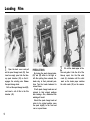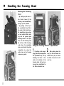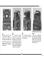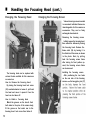
1
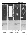
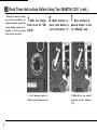
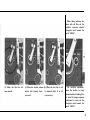
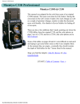
CONTENTS
We are highly gratified that you have selected the MAMIYA
C330 from among so many makes of cameras on the
market.
Before using the camera, please read these instructions very carefully, and learn the correct method of handling it.
By becoming completely familiarized with the
MAMIYA C330, you can make the most of the splendid opportunities this fine camera offers for many years to come.
This MAMIYA C330, an exceptionally high-grade camera,
was designed by emphasizing further improvements on the
popular MAMIYA C series. Retaining the many features of
the MAMIYA C series cameras which have won highest
praise from professional photographers the world over as
unique twin-lens reflex cameras (2 1/4 in. square format)
with interchangeable lenses, especially stressed was minimizing size and weight plus handling ease.
Final results reveal that this MAMIYA C330, an ideal
camera for professional photographers, is also a wise
choice for the many advanced amateurs who wish to take
advantage of fine details in enlargements which only a
large-format camera truly makes possible.
The MAMIYA C330 accepts all interchangeable lenses of
the current Mamiya C series as well as all of the accessories
except the single-exposure attachment.
In addition, various new accessories have been designed
for this model. With the wide selection of all these interchangeable lenses and accessories, you can further widen
your scope of photography by making the most of the
unlimited versatility the MAMIYA C33O offers.
1
page
Read These Instructions Before Using Your
2
MAMIYA C330 . . . . . . . . . . . . . ...............................
5
Nomenclature of Operating Parts . . . . . . . . . . . . . . . . .
Opening and Closing the Back Cover . . . . . . . . . . . . . . . 7
8
Before Loading Film .......................................
9
Loading Film ...................................................
11
Handling the Focusing Hood ...........................
13
Changing the focusing hood ........................
13
Changing the focusing screen .....................
14
Before Taking Pictures ....................................
Setting the parallax correcting dial ............... 14
14
Correcting parallax .......................................
14
Compensating exposure ..............................
Indicating film speed and type on respective
15
windows.. .................................................
Distance S c a l e ................................................
16
Taking Pictures .............................................
17
Shutter Operations .........................................
18
Using the multiple exposure selector ............ 18
18
Locking the shutter button ...........................
When no film is loaded in the camera ......... 19
20
Photographing by Flash Unit ...........................
Changing Lenses .............................................
21
Changing the Back Cover.. ...............................
23
23
Tripod Socket ................................................
24
Accessories ...................................................
Lens Specifications Table. . ...............................
32
Depth of Field Table.. .....................................
34
System chart f o r MAMIYA C330 .....................
41
Read These lnstructions Before Using Your
See page 8
for details.
See page 9
for details.
See page 7
for details.
C330
C330
See page 74
for details.
2
Read These lnstructions Before Using Your MAMIYA C330 (cont.)
When this camera is under
any of the conditions described as follows, the shutter
release button cannot be depressed. In this case, absolutelv do not use force.
1. When lens change 2 . When shutter re- 3 . When multiple exknob is set on “UNLOCK".
A red warning signal is
visible on the focusing screen.
lease lock button is posure button is set
set on the letter “L”. on “SINGLE,” and . . .
(1) When film is not loaded
(exposure counter indicates
“0”).
3
’
When taking ordinary pictures with roll film, set the
multiple
exposure selector
triangular mark toward the
word “SINGLE.."
(2) When the film has not
(3) When the shutter release (4) When the last film in roll
been wound.
button
has
pressed.
already
been
is exposed (after 12 or 24
exposures).
For multiple exposures,
when the shutter is freely
released without loading film,
or when the single exposure
attachment is used, set the
triangular mark toward the
word “MULTI.”
4
Nomenclature of Operating Parts
1.
2.
3.
4.
5.
6.
7.
10.
--@
--@
11.
12.
13.
Magnifying glass
Strap eyelet
Exposure counter
Shutter release lock button
Multiple exposure selector
Film wind crank
Shutter release button (upper)
Focusing knob
Sportsfinder frame (for 65mm
lens)
Sportsfinder frame (for 80mm
lens)
Sportsfinder mask stud
Sportsfinder flap
Synchroflash terminal
14.
15.
16.
17.
18.
19.
20.
21.
22.
23.
24.
25.
26.
27.
Synchroflash M-X selector
Shutter speed ring
Aperture ring
Shutter cocking lever
Aperture control knob
Shutter release button (lower)
with cable release socket
Lens catch bracket
Accessory shoe
Spool change knob (upper)
ASA indication shifting lever
Lens change knob
Parallax correcting dial
Film type indication select lever
Distance scale window
28.
29.
30.
31.
32.
33.
34.
35.
36.
37.
38.
39.
40.
41.
Distance scale revolving knob
Spool change knob (lower)
Focusing hood lock screw
Back cover catch button
Film indicating window (120/
220)
Back cover hinge release
Tripod socket
Eye opening for sportsfinder
Focusing screen frame catch
Focusing screen frame guide pin
Take-up spool chamber
Start mark
Film chamber
Film pressure plate
n
Opening and Closing the Back Cover
Twist the back cover catch button
(31) until the red mark on the button
faces upward. Then, by pressing the
button in the direction indicated on
the back cover, the back cover will
open. The figure i n t h e exposure
counter automatically returns to “0”
when the back cover opens.
7
When closing the back cover, firmly
press both sides of the back cover
catch button, making sure that
neither side of the back cover is open
or loose. Unless the back cover is
closed tightly, the automatic film
stopper will not work. Also, if only
one side of the back cover is pressed
when closing, the automatic film
stopper may not function.
When the back cover is closed, by
twisting the back cover catch button
counterclockwise until the red mark
of the button is on the left side, the
back cover can be locked. If the
button is twisted and the red mark
moved to the left side before closing,
the back cover will automatically lock
when closed.
Before Loading Film
This camera accepts either 120 or
220 roll film. It has an automatic
film stopper and a double exposure
prevention device. Take the following
steps before loading a film:
By turning the multiple exposure s e l e c t o r ( 5 ) , s e t t h e
triangular mark toward the word
“SINGLE.”
This action locks the shutter release
button until the film is wound. preventing accidental double exposures.
1
2
Adjust direction of the press u r e p l a t e a c c o r d i n g to the
film used.
Open the back cover, twist the pressure plate (41) either to the right or
left 90 degrees until the red mark
on the pressure plate matches either
120 or 220.
Subsequently, when closing the back
cover the film stopper mechanism
is automatically set to coincide with
the film frame number.
The figure 120 or 220 will appear
in the film indicating window (32).
informing the user of the loaded film
size when the back cover is closed.
8
Loading Film
1
Open the back cover and pull
out the spool change knob (22), then
insert an empty spool into the takeup spool chamber (38) so that it
engages the winding axis. Release
the spool change knob.
Pull out the spool change knob (29),
and insert a roll of film in the film
chamber (40).
9
PRECAUTIONS
By turning the spool change knobs
(22) and (29) either to the right or
left after pulling them outward, the
knobs stay at their protruded positions. Turn the knobs backward to
reinsert them.
If both spool change knobs are not
returned to their original positions
after loading a film, unbalanced film
winding will result.
Should the spool change knob not
return to its original position, move
the spool slightly to the front and
rear or up and down.
2
Pull out the leader paper of the
film and guide it into the slit of the
take-up spool, turn the film wind
crank (6) clockwise until the start
mark on the leader paper matches
the start marks (39) on the camera.
3
Close the back cover. When
closing the back cover, firmly press
both sides of the back cover catch
button. Twist the button counterclockwise, so that the back cover
does not open unexpectedly.
4
Turn the film wind crank (6)
clockwise until it stops. Figure 1
appears on the exposure counter (3)
at the position where the crank stops
diagonally upward, and the shutter
is automatically set. Now the camera
is prepared for the first exposure.
T h e c r a n k cannot b e t u r n e d i n
reverse.
Turn the crank each time one
picture is exposed. Regardless of the
number of pictures taken, the crank
always stops at a diagonally upward
position. In this position, when folding the crank in the opposite direction, the crank can be recessed in
the body.
10
n
Handling the Focusing Hood
Raising the Focusing
Hood
.
By pulling up the rear of
t h e f i n d e r f r a m e (9), the
focusing hood automatically
springs up into position.
By pushing in the top of
the sportsfinder flap (12) at
the center of the finder frame,
the magnifying glass swings
up into position. While looking into the ground glass
focusing screen in this position, turn the focusing knob
(8) to focus. After focusing,
push down the magnifying
glass, and decide the photo
composition by using the
entire view on the focusing
screen as a guide.
Using the Focusing Hood as a Sportsfinder
1
By pulling up the magnifying glass and pushing down
the sportsfinder flap, and by
attaching the latter to the
catch at the bottom of the
focusing hood, the hood can
be used as a sportsfinder for
the 80mm standard lens.
2
After pushing down the
flap (12). also fold down the
finder frame (10) to obtain
the field of view for the 65
mm lens.
3
When using the 105
m m , 135mm, 1 8 0 m m , o r
250mm lens, attach the
respective sportsfinder mask
for the lens used on the
finder mask stud (11), adjusting for the change in
field of view.
4
5
To return the finder
frame (10) to its original
position, by pushing and
releasing the left side plate
of the hood with a finger tip
(left side when the camera is
held for photographing), the
finder frame will automatically return to its position.
To return the sportsfinder flap (12), push the
right side plate.
Folding the Focusing
Hood
Return the
sportsfinder
flap, push down the magnify
ing glass, fold the side plates
inward and the back plate
downward, finally folding the
finder frame (9).
12
n
Handling the Focusing Hood (cont.)
Changing the Focusing Hood
Changing the Focusing Screen
Various focusing screens inserted
in convenient individual frames are
interchangeable for this camera as
accessories. They can be freely
exchanged when desired.
Removing the focusing screen
Initially remove the focusing hood,
then extend the bellows by turning
the focusing knob. Release the
frame catch (36) by turning it in
the direction of the arrow, as shown
in the photo. Next, by pulling
back the focusing screen frame
after raising its front portion upward, the focusing screen frame
can be removed.
The focusing hood can be replaced with
various finders available for this camera as
accessories.
How to Remove the Focusing Hood
By turning the focusing hood lock screw
(30) counterclockwise to loosen it, pull back
the hood a n d move it upward: then the
hood can be taken off.
How to Attach a Focusing Hood
Match the grooves on the hood’s front
both sides to the pins of the camera body,
fit the groove on the hood’s rear to the
focusing hood lock screw. then fasten it.
13
Installing the focusing screen
After positioning the two holes
on the rear side of the focusing
screen
the two guide pins (37)
n
Before Taking Pictures
Setting the Parallax Correcting Dial
By turning the parallax correcting dial (25), set the dial index to the focal length
of the lens used. Subsequently. while the lens is being extended, the pointer will
appear on the upper, left portion of the focusing screen. The position of this
pointer indicates parallax and the exposure factor.
Correcting parallax:
When the pointer appears on the focusing screen. the upper portion visible above
the pointer will be cut off on the film.
Be sure that the subject is satisfactorily
appears under the lower portion of this pointer. When using the camera on a
tripod, use the Paramender (parallax corrrecting device) to ensure that the camera
photographs the same image viewed on the focusing screen through simple
operations.
Compensating exposure:
X
As distance between the lens and film increases. image brightnea on the film is
reduced even though aperture size remains the same. Consequently, it is necessary
-1.5
.1.5
to increase the exposure.
-2
-2.5
-3
0
The figures on the focusing screen left side indicate the exposure factor. Compensate the exposure after reading the figure indicated by the pointer while focusing.
For instance. assuming that the correct exposure value measured by an exposure
meter is 1/125 sec. at f/11, compensate the exposure as follows:
If the pointer indicates 2, 1/125 sec., f/8
or 1/60 sec., f/11
If the pointer indicates 3, 1/125 sec., between f/S and f/5.6
or 1/60 sec., between f/11 and f/8
14
Indicating Film Speed and Type on Respective Windows
By turning the ASA
indication shifting lever (23) while pushing it against the
camera body, the film speed (ASA) will appear in the window. Set it to the speed
of the loaded film.
By turning the film type indication select lever (26), three types of identifying
marks will appear in the window. Use these marks as a film memory guide (black
and white, daylight color, and tungsten type color).
When using a 55mm or 65mm lens, set the dial (25) to 80 and attach the
parallax correction plate for 55mm/65mm lenses to the focusing hood.
How to install the parallax correction plate:
Remove the focusing hood from the camera and turn it inside out.
Also turn the
correction plate inside out and insert its chamfered edge in the two catches on the
hood, then fit the correction plate while pulling out the slide lock on the opposite
side. When the slide lock is released, the plate is secured.
The figures visible on the left side of the correction plate after attaching the
focusing hood to the camera reveal the exposure factor. Observe the line on the
right for correcting parallax. When the pointer indicates 1.5, the upper portion of
the first line will be cut off. In turn, this becomes a correcting scale when the
exposure factor is 2, 2.5 and 3.
.
Distance Scale
Replacing the Distance
Scale
To remove the distance scale,
at first, fully extend the bellows
by turning the focusing knob,
then remove the scale end cover
by sliding it to the front. Next,
pull out the distance scale after
detaching it from the bearing,
by holding the distance scale
revolving knob portion while
pressing in the distance scale
shaft with a pointed, fine wire.
A distance scale is provided on the left side (viewing
the camera held for photographing). By turning the
knob (28), set the distance scale to coincide with the
lens used, so that the scale faces horizontally.
Distance scales for 55mm, 65mm, and 80mm lenses
are indicated in red. Read these scales at the index
position in the window.
D i s t a n c e s c a l e s f o r 105mm, 135mm, 180mm, a n d
250mm lenses are indicated in black. Read these
scales at the front end of the camera body side plate.
Since the flange-focal length varies between the 105
mm F3.5DS or 105mm F3.5D lens and the ordinary
105mm F3.5 lens, a distance scale is especially provided.
A distance scale marked 105D.DS is used for 105mm
DS and 105mmD lenses (There are two types, scaled
in feet or meters.).
A distance scale marked 105 is used for ordinary 105
mm lens (There are two types, scaled in feet or meter.).
Distance graduations of lenses other than the 105mm
lens are all the same.
When installing the distance
s c a l e , i n s e r t t h e s h a f t tip opposite the revolving knob into
the camera body bearing. In this
case, insert the shaft tip while
pressing the spring located near
the bearing to the inner side, at
the side of the scale. Next, fit
the shaft to the bearing while
pushing in the shaft tip with a
finger nail; then install the
cover as it originally was.
16
in
ictures
1. After focusing, turn the shutter speed ring (15) and set the
shutter speed; then adjust the aperture of the lens by turning the aperture control knob (18). Now the camera is
prepared for taking pictures.
2. Release the shutter by pressing the shutter release button
(7) or (19). When a cable release is used, screw its tip into
the cable release socket in the lower button (19).
3. After each exposure, wind the film by turning the film wind
crank, then follow the same routine as mentioned above.
How to Remove Film
When all film frames have been exposed, the film winding stop
Remove the film after
mechanism is automatically released.
winding the remaining leader paper on the film end.
Winding Up the Roll Film
To remove film before exposing the entire roll, or to wind up
a short roll of film after exposure (6-exposure color films), turn
the film wind crank while depressing the shutter button on the
camera body after winding the exposed frame.
film can be completely wound without stopping.
In this manner,
n
Shutter Operations
Using the Multiple Exposure Selector
When the multiple exposure selector triangular
mark is set toward the word “SINGLE,” double
exposures are prevented.
Once the shutter
button has been depressed, it
Locking the Shutter
Button
By shifting the lock button (4)
toward the letter “L”, the shutter
c a n o t be
button is locked. While suspend-
without first advancing the film.
ing photography or the camera is
When the multiple exposure selector triangular
stored in the case, even though
mark is set toward the word “MULTI,” the
the shutter has been cocked by
shutter
repeatedly
film winding inadvertently releas-
regardless of advancing film. This proves con-
ing the shutter can be prevented.
redepressed
button can
be depressed
venient in the following cases:
1. When multiple exposures are desired.
2. For operations without loaded film (such
as shutter testing).
3.
When
photographing
with
the
single-ex-
posure attachment.
When photography is suspended by a missing
chance to release the shutter in spite of deeply
depressing the shutter button half way, it rarely
happens
that
the
shutter
button
cannot be
depressed on the next attempt. In this case,
by setting the mark on “MULTI.” pictures can
be taken without needlessly advancing the film.
18
For certain lens-shutter assemblies,
the
release
lever
for
the
shutter
itself can be depressed many times
even though the shutter is not
cocked, the same as the 80mm f/
3.7 lens. (When the shutter is not
cocked, the shutter blades do not
open).
When using this type of lens shutter, if the shutter button is depressed
without cocking the shutter, no pic-
When No Film is Loaded in
the Camera
Even when the film wind crank is
turned, the number in the exposure
c o u n t e r r e m a i n s a t “0”. I n t h i s
case, if the multiple exposure button
is set on “SINGLE,” the shutter
release button cannot be depressed.
However, when a takeup spool is in
the take-up spool chamber, although
no film is loaded, the counter may
be advanced (depending upon the
type of spool). In this case, roller
connected to a film will run idle.
causing wear on the roller and proving undesirable to turn the film wind
crank in this condition.
19
ture will be recorded on the film.
Concerning
the
unopened
shutter
blades, even though the shutter is
cocked manually, the shutter button
will not operate due to action of the
double-exposure-preventing device. In
this case, also, set the multiple exposure button triangular mark toward
“MULTI”
button,
and
or
depress
release
the
the
shutter
shutter
by
pushing the release lever on the lensshutter assembly.
2 5 0 m m f/6.3 a n d 80mm f / 3 . 7
lenses :
Shutters of these lenses have no
self-cocking system. requiring the
shutter to be set manually after each
film advance.
n
Photographing by Flash Unit
When photographing by flash, attach a flash gun to the accessory shoe (21)
on the camera body and connect the cord to the flash synchro-terminal (13).
When M-class flash bulbs are used, set the synchroflash M-X selector (14)
on M to synchronize flash at all shutter speeds.
When an electronic flash unit is used, set the synchroflash M-X selector on
X to synchronize flash at all shutter speeds.
This synchroflash M-X selector can be changed even after cocking the shutter.
When photographing without flash, keep the selector on X.
FLASH
SYNCHRONIZATION
TABLE
I
Shutter Soeed
M
X
M class
0
0
0
0
Electronic Flash
0
0
0
0
0
0
F class
0
0
0
0
0
M class
0
0
0
0
0
0
0
0
0
0
0
0
0
0
0
0
0
0
0
0
0
x
x
x
0
x
x
x
x
Combinations with the 0 mark synchronize.
Combinations with the x mark do not synchronize.
20
4
Changing
lenses
By turning the focusing knob, completely retract the bellows so that
the lens mount portion contact to the
body. Recess the film wind crank in
the camera body.
Turn the lens change knob (24) so
that the triangular mark points to the
word “UNLOCK.”
21
Tip the camera so that the lens
faces upward. and while firmly grasping the lens barrel pinch the head of
the lens catch bracket (20), press the
head toward the camera body, push
it down to release the lens catch,
and remove the lens.
To attach another lens tothe camera
body, carefully position the lens so
that the lens shutter cocking lever
(17) connects with the cocking lever
on the camera body. This operation
is correctly performed by previously
cocking the lens shutter with the
fingers, first inserting the lens from
the cocking lever side on the body.
Clamp the lens catch (20) to its original position, and turn the lens change
knob (24) clockwise to the “LOCK”
position. With this operation, lens
replacement is completed.
PRECAUTIONS
1.
If the film wind crank is not kept positioned
diagonally upward, (the same angle as the
crank housing position), the cocking lever (17)
cannot be connected with the cocking lever on
the camera body.
2. Regarding the cocking lever on the 180mm
lens, an auxiliary lever for connection is provided
on the side of the lens barrel. Since this lever
is constantly pushed upward by a spring, when
mounting the lens, hold the auxiliary lever
downward with a finger tip to prevent obstructing installation.
After changing a lens, set the parallax correcting dial (25) to the focal
length value of the mounted lens.
Regarding 55mm and 65mm lenses,
set the parallax correcting dial to 80.
then attach the parallax correction
plate for 55mm/65mm lenses to the
focusing hood. (Refer to p. 15 for
handling method of the focusing
hood).
Concerning the 250mm lens, set
the parallax correcting dial to 180.
3.
When the lens change knob (24) is in the
“UNLOCK” position, the portion to which the
picture taking lens (lower lens) is attached is
protected by a cover from the camera interior
to shield the film from exposure to light, and
a red warning signal is visible on the focusing
screen surface.
Should this cover be pushed while removing the
Never push it.
lens, light will strike the film.
4. After changing a lens, turn the lens change
knob (24) to the “LOCK” position; otherwise,
the shutter release button cannot be depressed.
22
II Angle of View Changes by Interchanging lenses
80mm
All these pictures were
taken from the same
position, at on identical
distance from the sub$Fi+jjy
ject.
35
105mm
135mm
# 1’
It i