1
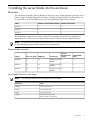
HP Integrity BL860c i2, BL870c i2, &
BL890c i2 Server Blade Installation Guide
HP Part Number: AD399-9004A
Published: April 2010
Edition: 1
© Copyright 2010 Hewlett-Packard Development Company, L.P.
Confidential computer software. Valid license from HP required for possession, use or copying. Consistent with FAR 12.211 and 12.212, Commercial
Computer Software, Computer Software Documentation, and Technical Data for Commercial Items are licensed to the U.S. Government under
vendor's standard commercial license.
The information contained herein is subject to change without notice. The only warranties for HP products and services are set forth in the express
warranty statements accompanying such products and services. Nothing herein should be construed as constituting an additional warranty. HP
shall not be liable for technical or editorial errors or omissions contained herein.
Acknowledgements
Intel, Itanium, Pentium, Intel Inside, and the Intel Inside logo are trademarks or registered trademarks of Intel Corporation or its subsidiaries in
the United States and other countries.
Microsoft, Windows, Windows XP, and Windows NT are U.S. registered trademarks of Microsoft Corporation.
Adobe and Acrobat are trademarks of Adobe Systems Incorporated.
Java is a US trademark of Sun Microsystems, Inc.
Oracle is a registered US trademark of Oracle Corporation, Redwood City, California.
UNIX is a registered trademark of The Open Group.
Warranty
WARRANTY STATEMENT: To obtain a copy of the warranty for this product, see the warranty information website:
http://docs.hp.com/en/5991-6026_ed3/5991-6026_ed3.pdf
Table of Contents
1 Installing the server blade into the enclosure..............................................................7
Overview.................................................................................................................................................7
Server blade overview.......................................................................................................................7
Server blade dimensions and weight...........................................................................................7
Server blade components..................................................................................................................8
SAS disk drives............................................................................................................................8
SAS disk backplane......................................................................................................................9
I/O subsystem...............................................................................................................................9
Partner blade support..................................................................................................................9
Memory subsystem......................................................................................................................9
DIMMs....................................................................................................................................9
Power subsystem..........................................................................................................................9
Processor and supporting chipset..............................................................................................10
ICH mezzanine card...................................................................................................................10
Scaleable BladeLink....................................................................................................................10
Enclosure information.....................................................................................................................10
Controls, ports, and LEDs...............................................................................................................11
Front panel view........................................................................................................................11
Front panel LEDs..................................................................................................................12
SAS disk drive LEDs.............................................................................................................13
Scaleable BladeLink LEDs.....................................................................................................15
SUV Cable and Ports.............................................................................................................16
Rear panel view..........................................................................................................................16
Safety information.................................................................................................................................17
Installation sequence and checklist.......................................................................................................17
Unpacking and inspecting the server blade.........................................................................................17
Verify site preparation.....................................................................................................................17
Inspect the shipping containers for damage...................................................................................18
Unpack the server blade..................................................................................................................18
Check the inventory.........................................................................................................................18
Damaged equipment returns..........................................................................................................18
Installing additional components.........................................................................................................18
Installing a hot-plug SAS disk drive................................................................................................19
Installing internal components........................................................................................................20
Removing the access panel.........................................................................................................20
Installing a processor and heatsink module..............................................................................21
Installing DIMMs.......................................................................................................................26
Installing mezzanine cards.........................................................................................................30
Replacing the access panel.........................................................................................................31
Installing and powering on the server blade........................................................................................32
Preparing the enclosure...................................................................................................................32
Removing a c7000 device bay divider........................................................................................33
Removing a c3000 device bay mini-divider or device bay divider............................................34
Installing interconnect modules.................................................................................................35
Interconnect bay numbering and device mapping...............................................................36
Installing the server blade into the enclosure..................................................................................37
Installing the Scaleable BladeLink...................................................................................................39
Server blade power states................................................................................................................41
Powering on the server blade.....................................................................................................41
Powering off the server blade....................................................................................................41
Using iLO..............................................................................................................................................41
Table of Contents
3
Accessing UEFI or the OS from iLO MP...............................................................................................42
UEFI Front Page...............................................................................................................................42
Saving UEFI configuration settings...........................................................................................44
Booting and installing the operating system...................................................................................44
Operating system is loaded onto the server blade..........................................................................44
Operating system is not loaded onto the server blade....................................................................44
OS login prompt..............................................................................................................................44
Installing the latest firmware using HP Smart Update Manager.........................................................45
2 Support and other resources.......................................................................................47
Contacting HP.......................................................................................................................................47
Before you contact HP.....................................................................................................................47
HP contact information...................................................................................................................47
Subscription service.........................................................................................................................47
Documentation feedback.................................................................................................................47
Typographic conventions......................................................................................................................47
Standard terms, abbreviations, and acronyms.............................................................49
Index.................................................................................................................................51
4
Table of Contents
List of Tables
1-1
1-2
1-3
DIMM pair load order...................................................................................................................27
DIMM quad load order.................................................................................................................28
Power States...................................................................................................................................41
5
6
1 Installing the server blade into the enclosure
Overview
The HP Integrity BL860c i2 Server Blade is a dense, low-cost, Intel® Itanium® processor server
blade. Using a Scaleable Blade Link hardware assembly, multiple BL860c i2 Server Blades can
be conjoined to create dual-blade four socket and quad-blade eight socket variants.
Name
Number of Conjoined Server Blades
Number of CPU Sockets
BL860c i2
1
2
BL870c i2
2
4
BL890c i2
4
8
The three blade configurations support the HP-UX operating system and are designed for
deployment in c-Class enclosures, specifically the 10U c7000 and the 6U c3000 Enclosures.
NOTE: For purposes of this guide, make sure that the c-Class server blade enclosure is powered
on and running properly and that the OA iLO is operational.
Server blade overview
PCIe I/O
Mezzanine card
capacity
SAS Hard Disk
Drives
Product
CPU cores (quad)
DIMM slots
max memory
BL860c i2
8
24
192GB with 8GB 3
DIMMs
2
BL870c i2
16
48
384GB with 8GB 6
DIMMS
4
BL890c i2
32
96
768GB with 8GB 12
DIMMS
8
Server blade dimensions and weight
NOTE:
These specifications are for the BL860c i2 Server Blade.
Dimensions
value
Height
36.63 cm (14.42 in.)
Width
5.14 cm (2.025 in.)
Depth
48.51 cm (19.1 in.)
Weight
Unloaded: 8.6 kg (19 lb)
Fully loaded: 11.3 kg (25 lb)
Overview
7
Server blade components
1
2
3
4
5
6
7
CPU0
CPU0 power connector
Mezzanine connector 1 (type 1)
Mezzanine connector 2 (type 1 or 2)
System board thumbscrew
Battery (CR2032)
System board thumbscrew
8
9
10
11
12
13
ICH mezzanine connector
Mezzanine connector 3 (type 1 or 2)
CPU1 power connector
CPU1
SAS backplane
Pull tab
SAS disk drives
The BL860c i2 Server Blade has SAS disk drive slots on the BL860c i2 server blade. The SAS disk
drives have identical LEDs that display the drive status.
8
Installing the server blade into the enclosure
For the location of the SAS disk LEDs, see “SAS disk drive LEDs” (page 13).
SAS disk backplane
The SAS disk backplane supports two small form factor hard disk drives. The backplane supports
hot-plugging a single SAS drive at a time. The activity LEDs and drive present LEDs are controlled
by a preprogrammed system-on-chip. The system board hosts the SAS controller and supplies
12 V, 5 V, and 3.3 V standby power to the backplane.
The SAS backplane is connected to the system board with a right angle connector. This connector
is specifically designed for high-speed differential applications, and supports server speeds
exceeding 5 Gigabits per second. Power, sense, and I2C signals are routed through this connector
as well as the SAS differential pairs and SGPIO signals.
I/O subsystem
The I/O subsystem is composed of embedded core I/O and up to three mezzanine cards. The
server blade supports the following configurations:
• Up to three type I mezzanine cards
• One type I and up to two type II mezzanine cards using up to x8-PCIe Gen-2 links
The server blade does not support PCI Hot Plug.
Partner blade support
The partner blades currently supported are the SB40c storage blade (411243-B21) and the HP
BLc PCI Expansion Blade (448018-B21).
Partner blade slotting rules are dependent on the conjoined blade configuration. For more
information on partner bay blade locations, see “Installing the Scaleable BladeLink” (page 39).
Memory subsystem
The BL860c i2 physical memory subsystem connects two Itanium® processors to two groups of
12 DDR3 DIMMs. Each processor has two memory controllers.
DIMMs
The memory subsystem supports only DDR3 SDRAM technology using industry-standard 1.2”
high DIMMs.
Single DIMM
sizes
BL860c i2 Min / Max BL870c i2 Min / Max
Memory size
Memory size
BL890c i2 Min / Max
Memory size
2 GB
8 GB / 48 GB
Not supported
Not supported
4 GB
8 GB / 96 GB
16 GB / 192 GB
32 GB / 384 GB
8 GB
16 GB / 192 GB
32 GB / 384 GB
32 GB / 768 GB
For more DIMM information, see “Installing DIMMs” (page 26).
Power subsystem
The power subsystem is located on the system board. Each server blade receives bulk DC voltage
from the enclosure. The server blade power block converts the DC voltage from the enclosure
to the voltage required by the server blade. The BL860c i2 Server Blade receives 12 V directly
from the enclosure. The voltage passes through E-Fuse circuitry that resides in the blade. The 12
V supply is on as long as a power supply is installed in the enclosure. A control line from the
enclosure OA can turn the E-Fuse on or off to supply or cut power to the blade. The 12 V gets
distributed to various POL converters. The switched POL voltage rails are: 0.9 V, 1.2 V, 1.5 V,
1.8 V, 2.5 V, 3.3 V, 5.0 V, 3.3 V standby, and 5.0 V standby.
Overview
9
Processor and supporting chipset
The BL860c i2 Server Blade contains a processor subsystem accommodating one or two Intel
Itanium processor modules.
Each processor module consists of the following:
• CPU chip, including CPU cores, QPI links for CPU-CPU and CPU-IO Hub chip connections,
and SMI links for CPU-Memory interface chip connections
• CPU power conversion module
• Heatsink, with mechanical attachment / assembly features
ICH mezzanine card
The ICH mezzanine card houses the following components:
•
•
•
•
Intel ICH10 South Bridge
ATI/AMD RN50/ES1000 Video Controller
Embedded TPM 1.2
The internal USB port
One ICH mezzanine card is required per system.
Scaleable BladeLink
Conjoining server blades using the Scaleable BladeLink enables four (BL870c i2) and eight (BL890c
i2) socket server blade variants.
In a conjoined configuration, one of the BL860c i2 Server Blades becomes the master blade, also
referred to as the monarch blade. The monarch server blade is in the lowest numbered enclosure
bay, communication to the conjoined server blade is done through the monarch blade.
Each Scaleable BladeLink includes a trap door for the label carrier. To access the label carrier:
1.
2.
Locate the indentation on the upper-right corner of the access door.
Use the indent to pull the door open.
For more information see “Installing the Scaleable BladeLink” (page 39).
Enclosure information
All three blade configurations are supported in c7000 and c3000 Enclosures.
For more enclosure information see:
10
Installing the server blade into the enclosure
http://h71028.www7.hp.com/enterprise/cache/316735-0-0-0-121.html.
Controls, ports, and LEDs
Front panel view
1
2
3
4
Monarch blade indicator
UID LED
Blade health LED
NICs 1, 2, 3, 4
CAUTION:
5
6
7
8
Monarch power button
HDD bay 1
HDD bay 2
Blade power LED
9
10
11
Partition Identifier
Physical Presence Button
SUV connector
The SUV cable is not designed to be used as a permanent connection.
Use caution when walking near the server blade when the SUV cable is installed. Hitting or
bumping the cable might cause the port on the server blade to break. This can damage the system
board.
Overview
11
Front panel LEDs
Item
Description
Status
1
Monarch blade indicator
Green = Blade is acting as monarch
blade
Off = Blade is not monarch or is not
conjoined
2
UID LED
Blue = Identified
Blue flashing = Active remote
management
Off = No active remote management
3
Blade health LED
Green = Normal operation
Amber flashing = Degraded condition
Red flashing = Critical condition
4
NICs 1, 2, 3, 4
Green = Network linked
Green flashing = Network activity
Off = No link or activity
5
Monarch power button / Monarch
power LED
Green = Blade is acting as monarch and
is powered on
Amber = Blade is acting as monarch
and is in standby
Off = Blade is not monarch
6
SUV connector
N/A
7
Physical Presence Button
N/A
8
Partition Identifier
Green = Blade is in a partition
Off = Blade is not in a partition
12
Installing the server blade into the enclosure
Item
Description
Status
9
Blade power LED
Green = Server blade is powered on
Amber = Standby (auxiliary power
available)*
Off = Off
Not shown (behind grill)
iLO Heartbeat
Green flashing = iLO Active
Amber flashing = iLO failure
Off = No standby voltage
*If the Onboard Administrator denies power to the server blade, the server blade returns to
Standby mode.
SAS disk drive LEDs
There are two disk drives on the BL860c i2 Server Blade. They have identical LEDs that display
the drive status.
Item
Description
1
Fault/UID LED (amber/blue)
2
Online LED (green)
SAS hard drive LED combinations
NOTE: Predictive failure alerts only occur when the hard drive is connected to a Smart Array
controller.
Online/activity LED (green)
Fault/UID LED (amber/blue)
Interpretation
On, off, or flashing
Alternating amber and blue
The drive has failed, or a predictive
failure alert has been received for this
drive; it also has been selected by a
management application.
On, off, or flashing
Steadily blue
The drive is operating normally, and
it has been selected by a management
application.
On
Amber, flashing regularly (1 Hz)
A predictive failure alert has been
received for this drive. Replace the
drive as soon as possible.
On
Off
The drive is online, but it is not active
currently.
Overview
13
14
Online/activity LED (green)
Fault/UID LED (amber/blue)
Interpretation
Flashing regularly (1 Hz)
Amber, flashing regularly (1 Hz)
Do not remove the drive. Removing
a drive might terminate the current
operation and cause data loss. The
drive is part of an array that is
undergoing capacity expansion or
stripe migration, but a predictive
failure alert has been received for this
drive. To minimize the risk of data
loss, do not replace the drive until the
expansion or migration is complete.
Flashing regularly (1 Hz)
Off
Do not remove the drive. Removing
a drive might terminate the current
operation and cause data loss. The
drive is rebuilding, erasing, or it is part
of an array that is undergoing capacity
expansion or stripe migration.
Flashing irregularly
Amber, flashing regularly (1 Hz)
The drive is active, but a predictive
failure alert has been received for this
drive. Replace the drive as soon as
possible.
Flashing irregularly
Off
The drive is active, and it is operating
normally.
Off
Steadily amber
A critical fault condition has been
identified for this drive, and the
controller has placed it offline. Replace
the drive as soon as possible.
Off
Amber, flashing regularly (1 Hz)
A predictive failure alert has been
received for this drive. Replace the
drive as soon as possible.
Off
Off
The drive is offline, a spare, or not
configured as part of an array.
Installing the server blade into the enclosure
Scaleable BladeLink LEDs
Description
Status
Busy LED
Green = Scaleable BladeLink is currently active. Do not
remove.
Off = Scaleable BladeLink is not currently active. Safe to
remove.
Overview
15
SUV Cable and Ports
The SUV port on the front of the server blade is used in conjunction with an SUV cable to connect
the server to external devices such as a terminal emulator or monitor.
CAUTION:
The SUV cable is not designed to be used as a permanent connection.
Use caution when walking near the server blade when the SUV cable is installed. Hitting or
bumping the cable might cause the port on the server blade to break. This can damage the system
board.
1
2
Server blade
Video
3
USB ports (2)
2
GBX signal connectors
Rear panel view
1
16
Power connectors
Installing the server blade into the enclosure
4
Serial
Safety information
WARNING! Wear an ESD wrist strap when handling internal server components. Acceptable
ESD wrist straps include:
• The wrist strap that is included in the ESD kit with circuit checker (part number 9300-1609).
• The wrist strap that is included in the ESD kit without circuit checker (part number 9300-1608).
• The throw away strap that ships with HP memory products.
When removing and replacing server components, use care to prevent injury and equipment
damage. Many assemblies are sensitive to damage by electrostatic discharge.
Follow the safety precautions listed to ensure safe handling of components, to prevent injury,
and to prevent damage to the server blade:
•
•
•
•
•
When removing or installing a server blade or server blade component, review the
instructions provided in this guide.
Do not wear loose clothing that might snag or catch on the server or on other items.
Do not wear clothing subject to static charge build-up, such as wool or synthetic materials.
If installing an internal assembly, wear an antistatic wrist strap, and use a grounding mat
such as those included in the Electrically Conductive Field Service Grounding Kit.
Handle components by the edges only. Do not touch any metal-edge connectors or electrical
components on accessory boards.
Installation sequence and checklist
Step
Description
Completed
1
Unpack and inspect the server shipping container and then inventory the contents using
the packing slip.
2
Install additional components shipped with the server.
3
Install and power on the server blade.
4
Configure iLO MP access.
5
Access iLO MP.
6
Access UEFI from iLO MP.
7
Download latest firmware using HP Smart Update Manager
8
Install and boot the OS.
Unpacking and inspecting the server blade
Ensure that you have adequately prepared your environment for your new server, received the
components that you ordered, and verified that the server and its containers are in good condition
after shipment.
Verify site preparation
Verifying site preparation is an essential factor of a successful server blade installation, and
includes the following tasks:
•
•
Gather LAN information. Determine the two IP addresses for the iLO 3 MP LAN and the
server blade LAN.
Establish a method to connect to the server blade console. For more information on console
connection methods, see Section : “Using iLO” (page 41) for more information.
Safety information
17
•
•
Verify electrical requirements. Ensure that grounding specifications and power requirements
are met.
Confirm environmental requirements.
Inspect the shipping containers for damage
HP shipping containers protect their contents under normal shipping conditions. After the
equipment arrives, carefully inspect each carton for signs of shipping damage. Shipping damage
constitutes moderate to severe damage, such as punctures in the corrugated carton, crushed
boxes, or large dents. Normal wear or slight damage to the carton is not considered shipping
damage. If you find shipping damage to the carton, contact your HP customer service
representative immediately.
Unpack the server blade
1.
2.
Use the instructions printed on the outside top flap of the carton.
Remove inner accessory cartons and the top foam cushions.
IMPORTANT:
3.
Inspect each carton for shipping damage as you unpack the server blade.
Place the server blade on an antistatic pad.
Check the inventory
The sales order packing slip lists the equipment shipped from HP. Use this packing slip to verify
that the equipment has arrived.
NOTE:
To identify each item by part number, see the sales order packing slip.
Damaged equipment returns
If the equipment is damaged, immediately contact your HP customer service representative. The
service representative initiates appropriate action through the transport carrier or the factory
and assists you in returning the equipment.
Installing additional components
If your server blade has no additional components to install, go to “Installing and powering on
the server blade” (page 32).
18
Installing the server blade into the enclosure
Installing a hot-plug SAS disk drive
The server blade supports up to two hot-plug SAS drives.
CAUTION: To prevent improper cooling and thermal damage, do not operate the server blade
or the enclosure unless all hard drive and device bays are populated with either a component
or a blank.
IMPORTANT: The disk drive will not seat properly when 180 degrees out of alignment. Check
the orientation before insertion.
NOTE: For a list of supported disk drives for the server blade, see:
http://h18004.www1.hp.com/products/blades/components/c-class-storage.html
1.
Remove the hard drive blank.
2.
Prepare the hard drive.
3.
Slide the drive into the cage until it is fully seated.
Installing additional components
19
4.
Close the lever to lock the drive into place.
Installing internal components
Removing the access panel
1.
2.
3.
Unlock the cam on the access panel latch (if necessary) by turning the lock on the access
panel latch counter-clockwise with a Torx T-15 or flathead screwdriver.
Pull up on the access panel latch. This causes the access panel to slide back about 2 cm (0.75
in).
Remove the access panel by lifting it straight up and off the server blade.
After the access panel is off, you can do the following:
•
•
•
20
Add an additional processor (“Installing a processor and heatsink module”).
Add additional memory DIMMs (“Installing DIMMs”).
Add additional mezzanine cards (“Installing mezzanine cards”).
Installing the server blade into the enclosure
Installing a processor and heatsink module
Processor load order
Observe the following guidelines when installing additional processors:
• In a BL860c i2, CPU0 is installed before CPU1.
• In a BL870 i2 or BL890 i2, each blade must have CPU0 installed.
• When adding additional CPUs in a conjoined configuration:
— Load both CPU0 and CPU1 in the monarch blade first
— Load additional CPUs in sequence, from lowest slot-numbered blade to highest.
CAUTION: The pins on the processor socket are very fragile. Any damage to them may require
replacing the server blade base unit.
CAUTION: To avoid damage to the processor, verify that the plastic tabs on the processor are
pulled fully out before installation.
CAUTION: To avoid damage to the processor, handle the processor only by the edges. Do not
touch the bottom of the processor, especially the contact area.
CAUTION: To prevent possible server blade malfunction and damage to the equipment,
multiprocessor configurations must contain processors with the same part number.
CAUTION: To prevent thermal instability and damage to the server, do not separate the processor
from the heatsink after assembling.
The processor and heatsink ship as two separate units and are coupled together during installation
into the server blade.
1.
Remove the CPU airflow baffle.
Installing additional components
21
2.
Transfer the duplicate part/serial numbers label from the processor module to the processor's
heatsink.
a. Remove the duplicate yellow tear-away label that lists the part and serial numbers from
the processor module.
b. Place the label on the top of the heatsink.
3.
Install the processor over the load posts.
NOTE: Ensure pin 1, indicated on the empty socket with an embossed triangle, matches
the pin 1 marker on the processor module, the chamfered corner of its attached voltage
regulator heatsink.
4.
22
Remove the heatsink cover.
Installing the server blade into the enclosure
CAUTION: During installation, after removing the protective cover from the heatsink:
• Do not touch or come into contact with the thermal interface material.
• Immediately install the heatsink.
Installing additional components
23
CAUTION: To avoid damage to the server blade and processor, ensure the processor
heatsink's locking handle is fully back against the stops, rotated about 120° back. Also verify
that the plastic tabs on the processor's heatsink are pulled fully out before installation.
5.
Install the heatsink over the load posts.
CAUTION: Do not lower the heatsink locking handle before pushing the plastic locking
tabs into place.
CAUTION: To prevent thermal instability and damage to the server blade, do not separate
the processor module from the processor's heatsink after they have been coupled.
NOTE: Positive engagement clicking should occur during mating of the processor heat
sink and processor module onto the socket to ensure proper seating.
24
Installing the server blade into the enclosure
6.
Secure the heatsink to the processor
a. Slide both plastic locking tabs into place (see callout 1 in the image below).
b. Flip the latch down (see callout 2 in the image below).
WARNING! The heatsink locking lever can constitute a pinch hazard, keep your hands
on top of the lever during installation to avoid personal injury.
CAUTION: To prevent thermal instability and damage to the server, do not separate
the processor module from the processor's heatsink after they have been coupled.
7.
Connect the power cord (see callout 3 in the image above).
Installing additional components
25
8.
Tie wrap the processor cable to the right tie point on the processor assembly.
CAUTION: When the CPU is installed, dress all slack in the power cable to the connector
end of the cable. Failure to do so could result in pinched or damaged CPU power cables.
NOTE: If you are adding an additional processor to your server blade, the DIMMs in the server
blade must be reconfigured to support both CPUs. See “DIMM pair load order” (page 27) for
more information.
Installing DIMMs
DIMM installation guidelines
Observe the following guidelines when installing additional memory:
• In a BL860c i2, memory is loaded in pairs.
• In a BL870 i2 or BL890 i2, memory is loaded in quads that alternate between blades.
• Only 2 DIMM sizes can be mixed in a BL870 i2 or BL890 i2.
— In a BL870c i2, the two DIMM sizes must alternate between blades. Load all of one
DIMM size, then repeat with the second DIMM size.
— In a BL890c i2, blade configuration, blades 1 and 2 must have one DIMM size and blades
3 and 4 must have the other DIMM size.
26
Installing the server blade into the enclosure
DIMM pair load order
Table 1-1 DIMM pair load order
CPU0
CPU1
1st
3A
4A
—
—
2nd
9B
10B
—
—
3rd
1C
6C
—
—
4th
7D
12D
—
—
5th
2E
5E
—
—
6th
8F
11F
—
—
1st
3A
4A
—
—
2nd
—
—
1A
7A
3rd
9B
10B
—
—
4th
—
—
6B
10B
5th
1C
6C
—
—
6th
—
—
3C
9C
7th
7D
12D
—
—
8th
—
—
4D
12D
9th
2E
5E
—
—
10th
—
—
2E
8E
11th
8F
11F
—
—
12th
—
—
5F
11F
CPU0 only
Both CPUs loaded
Installing additional components
27
DIMM quad load order rules
Table 1-2 DIMM quad load order
CPU0
Both CPUs
loaded
28
CPU1
1st
3A
4A
9B
10B
—
—
—
—
2nd
—
—
—
—
1A
7A
6B
10B
3rd
1C
6C
7D
12D
—
—
—
—
4th
—
—
—
—
3C
9C
4D
12D
5th
2E
5E
8F
11F
—
—
—
—
6th
—
—
—
—
2E
8E
5F
11F
Installing the server blade into the enclosure
DIMM locations
To install the DIMMs:
1.
Remove the DIMM baffle.
2.
Locate the DIMM slots on the server blade system board.
Installing additional components
29
NOTE:
3.
The server blade ships with at least two DIMMs installed in slots 3A and 4A.
Ensure the DIMM slot latches are open.
CAUTION: Use only HP low profile (1.2 in.) DIMMs. DIMMs from other sources might
adversely affect data integrity.
DIMMs do not seat fully if turned the wrong way.
DIMMs in a pair or quad must be identical.
4.
Insert a DIMM in a slot and push down firmly until the latches click shut.
Installing mezzanine cards
Optional mezzanine cards enable additional network connectivity and provide Fibre Channel
support. For mezzanine card locations, see “Server blade components” (page 8).
Optional mezzanine cards are classified as Type I mezzanine cards and Type II mezzanine cards.
The card type determines where it can be installed in the server blade:
• Install Type I mezzanine cards on any mezzanine connector.
• Install Type II mezzanine cards only on Mezzanine 2 connector or Mezzanine 3 connector.
To install a card:
30
Installing the server blade into the enclosure
1.
Remove the mezzanine connector cover.
2.
Align the mezzanine connector on the option card with the mezzanine connector on the
system board.
Install the mezzanine card. Press down on the connector to seat the card:
3.
CAUTION: To prevent damage to the server blade, apply pressure over the mezzanine
connector when installing the mezzanine card. Do not apply pressure to the edges of the
card.
NOTE: The HP Smart Array P700m Controller requires additional procedures for installation.
Refer to the HP Integrity BL860c i2, BL870c i2 & BL890c i2 Server Blade User Service Guide for more
information.
Replacing the access panel
1.
Make sure the access panel latch is in the open position (pointing up).
Installing additional components
31
2.
3.
4.
Place the access panel onto the server blade by lining up the posts on each side of the access
panel with the keyways on the server blade chassis.
Slide the access panel toward the front of the server blade, and push down on the access
panel latch until it is flush with the access panel.
Lock the access panel cam (if necessary) by turning the cam clockwise with the Torx T–15
or flathead screwdriver.
Installing and powering on the server blade
Preparing the enclosure
HP BladeSystem enclosures ship with device bay dividers to support half-height devices. To
install a full height device, remove the blanks and the corresponding device bay divider.
CAUTION: To prevent improper cooling and thermal damage, do not operate the server blade
or the enclosure unless all hard drive and device bays are populated with either a component
or a blank.
32
1.
Remove the device bay blank.
2.
Remove the three adjacent blanks.
Installing the server blade into the enclosure
Removing a c7000 device bay divider
1.
Slide the device bay shelf locking tab to the left to open it.
2.
Push the device bay shelf back until it stops, lift the right side slightly to disengage the two
tabs from the divider wall, and then rotate the right edge downward (clockwise).
Installing and powering on the server blade
33
3.
Lift the left side of the device bay shelf to disengage the three tabs from the divider wall,
and then remove it from the enclosure.
Removing a c3000 device bay mini-divider or device bay divider
1.
34
Slide the locking tab down.
Installing the server blade into the enclosure
2.
Remove the mini-divider or divider:
• c3000 mini-divider:
Push the divider toward the back of the enclosure until the divider drops out of the
enclosure.
•
a.
b.
c.
d.
c3000 divider
Push the divider toward the back of the enclosure until it stops.
Slide the divider to the left to disengage the tabs from the wall.
Rotate the divider clockwise.
Remove the divider from the enclosure.
Installing interconnect modules
For specific steps to install interconnect modules, see the documentation that ships with the
interconnect module.
Installing and powering on the server blade
35
Interconnect bay numbering and device mapping
•
HP BladeSystem c7000 Enclosure
•
HP BladeSystem c3000 Enclosure
To support network connections for specific signals, install an interconnect module in the bay
corresponding to the embedded NIC or mezzanine signals.
36
Server blade signal
c7000 interconnect bay
c3000 interconnect bay
NIC 1 (Embedded)
1
1
NIC 2 (Embedded)
2
1
NIC 3 (Embedded)
1
1
NIC 4 (Embedded)
2
1
Mezzanine 1
3 and 4
2
Installing the server blade into the enclosure
Interconnect bay labels
Server blade signal
c7000 interconnect bay
c3000 interconnect bay
Mezzanine 2
5 and 6
3 and 4
7 and 8
3 and 4
5 and 6
3 and 4
7 and 8
3 and 4
Mezzanine 3
Interconnect bay labels
For detailed port mapping information, see the HP BladeSystem enclosure installation poster or
the HP BladeSystem enclosure setup and installation guide for your product on the HP website
(http://www.hp.com/go/bladesystem/documentation).
Installing the server blade into the enclosure
NOTE: When installing additional blades into an enclosure, additional power supplies might
also be needed to meet power requirements. For more information, see the HP BladeSystem
enclosure setup and installation guide for your product on the HP website (http://www.hp.com/
go/bladesystem/documentation).
NOTE: Before installing and initializing the server blade, install any server blade options, such
as an additional processor, hard drive, or mezzanine card.
NOTE: Refer to the HP Integrity BL860c i2, BL870c i2 & BL890c i2 User Service Guide for
information regarding SAS controller configuration.
1.
Remove the connector covers if they are present.
2.
Prepare the server blade for installation.
Installing and powering on the server blade
37
3.
Install the server blade.
The server blade should come up to standby power. The server blade is at standby power if the
blade power LED is amber.
38
Installing the server blade into the enclosure
Installing the Scaleable BladeLink
NOTE: Before installing the Scaleable BladeLink for BL870c or BL890c, make sure the following
statements are true:
• All blades have the same CPU SKUs.
• All blades have the same hardware revision
• All blades have CPU0 installed.
• All blades follow the memory loading rules for your configuration, see “Installing DIMMs”
(page 26).
• The enclosure OA firmware is compatible with the blade firmware.
• The monarch blade has an ICH mezzanine card installed.
Scaleable BladeLink bay location rules
Class
Scaleable
BladeLink part
number
Number of
conjoined Supported
blades
enclosures
Blade location
rules
SBL1
AD399-60002
1 (standard c7000
for BL860c
i2)
No specific bay Yes
location rules
for blades
Partner blade
support?
c3000
SBL2
SBL2E
AD399-60003
2 (BL870c
i2)
Partner blade
bay location rules
in half-height
blade device
bays
Right bottom or
left bottom
half-height
adjacent bay
paired with the
server blade in
full-height bays
1&2, 3&4, 5&6, or
7&8.
Top right or
bottom right
half-height
adjacent bay
paired with the
server blade in
full-height bays
1&2 or 3&4.
c7000
Bays 1&2, 3&4,
5&6, or 7&8
with monarch
blade in odd
bay
c3000
Bays 1&2, 3&4
with monarch
blade in odd
bay
No
N/A
AD399-60010
2 (BL870c
i2)
c7000 only
Bays 2&3, 4&5
or 6&7 with
monarch blade
in even bay
Yes
Odd bottom
half-height bay
adjacent to
monarch blade.
AD399-60011
2 (BL870c
i2)
c3000 only
Bays 2&3 with
monarch blade
in even bay
Yes
Top right or
bottom right
half-height
adjacent bay.
Installing and powering on the server blade
39
Partner blade
bay location rules
in half-height
blade device
bays
Class
Scaleable
BladeLink part
number
Number of
conjoined Supported
blades
enclosures
Blade location
rules
SBL4
AD399-60006
4 (BL890c
i2)
c7000 only
Bays 1, 2, 3, 4 or No
5, 6, 7, 8
N/A
AD399-60007
4 (BL890c
i2)
c3000 only
Bays 1, 2, 3, 4
N/A
Partner blade
support?
No
To install the Scaleable BladeLink:
1.
2.
Log on to the OA.
Install the first blade into the lowest bay number, this blade becomes the monarch blade
(“Installing the server blade into the enclosure”).
3. Wait 10 seconds. The IP address of the installed blade will appear in the OA.
4. Insert each adjacent blade, waiting 10 seconds between blades.
5. Using the OA, verify that the rest of the blades that will be conjoined have an IP address
and are powered off.
6. Remove the plastic protectors from the connectors on the back of the Scaleable BladeLink.
7. Push in the blue release latch on the handle to release the handle.
8. Pull the handle all the way out
9. Align the guide pins on the back of the Scaleable BladeLink to the holes on the front of the
server blades.
10. Fully insert the Scaleable BladeLink into the blades, and then close the handle.
11. Log into iLO on the monarch blade. For more information, see the HP Integrity iLO3 Operations
Guide.
12. In iLO, go to the Command Menu and execute xd -r to reboot iLOs in the conjoined set.
13. Still in the iLO Command Menu, power on the monarch blade with the PC -on -nc
command. Powering on the monarch blade will power the entire conjoined system on.
14. Boot the monarch blade. Booting the monarch blade boots the entire conjoined system.
40
Installing the server blade into the enclosure
Server blade power states
The server blade has three power states: standby power, full power, and off. Install the server
blade into the enclosure to achieve the standby power state. Server blades are set to power on
to standby power when installed in a server blade enclosure. Verify the power state by viewing
the LEDs on the front panel, and using Table 1-3.
For more front panel LED information, see “Front panel LEDs” (page 12).
Table 1-3 Power States
Power States
Server Blade Installed
in Enclosure?
Front Panel Power
Button Activated?
Standby Power
Applied?
DC Power Applied?
Standby power
Yes
No
Yes
No
Full power
Yes
Yes
Yes
Yes
Off
No
No
No
No
Powering on the server blade
Use one of the following methods to power up the server blade:
NOTE:
•
•
To power on blades in a conjoined configuration, only power on the monarch blade.
Use a virtual power button selection through iLO.
Press and release the monarch power button.
When the server blade goes from the standby mode to the full power mode, the blade power
LED changes from amber to green.
For more information about iLO, see “Using iLO” (page 41).
Powering off the server blade
Before powering down the server blade for any upgrade or maintenance procedures, perform a
backup of critical server data and programs.
Use one of the following methods to power down the server blade:
NOTE:
•
To power off blades in a conjoined configuration, only power off the monarch blade.
Use a virtual power button selection through iLO (Power Management, Power & Reset).
This method initiates a controlled remote shutdown of applications and the OS before the
server blade enter standby mode.
•
Press and release the monarch power button.
This method initiates a controlled shutdown of applications and the OS before the server
blade enter standby mode.
•
Press and hold the monarch power button for more than 4 seconds to force the server blade
to enter standby mode.
This method forces the server blade to enter standby mode without properly exiting
applications and the OS. It provides an emergency shutdown method in the event of a hung
application.
Using iLO
The iLO subsystem is a standard component of selected server blades that provides blade health
and remote server manageability. The iLO subsystem includes an intelligent microprocessor,
secure memory, and a dedicated network interface. This design makes iLO independent of the
Using iLO
41
host server and operating system. The iLO subsystem provides remote access to any authorized
network client, sends alerts, and provides other server management functions.
Using iLO , you can:
•
•
•
•
Remotely power up, power down, or reboot the host server.
Send alerts from iLO regardless of the state of the host server.
Access advanced troubleshooting features through the iLO interface.
Diagnose iLO using HP SIM through a web browser and SNMP alerting.
For more information about iLO basic features, refer to the iLO documentation on the HP website
(http://www.hp.com/servers/lights-out).
Accessing UEFI or the OS from iLO MP
The Unified Extensible Firmware Interface is an architecture that provides an interface between
the server blade OS and the server blade firmware. UEFI provides a standard environment for
booting an OS and running preboot applications.
Use this procedure to access UEFI or the OS from the iLO MP. Your security parameters were
set regarding remote access.
•
From the MP Main Menu, enter co to access the Console.
NOTE: Terminal windows should be set to a window size of 80 columns x 25 rows for
optimal viewing of the console at UEFI.
Depending on how the server blade was configured from the factory, and if the OS is installed
at the time of purchase, you are taken to:
•
•
UEFI shell prompt
OS login prompt
If the server blade has a factory-installed OS, you can interrupt the boot process to configure
your specific UEFI parameters.
If you are at the UEFI shell prompt, go to “UEFI Front Page” (page 42).
If you are at the OS login prompt, go to “OS login prompt” (page 44).
UEFI Front Page
If you are at the UEFI shell prompt, enter exit to get to the UEFI Front Page.
42
Installing the server blade into the enclosure
To view boot options, or launch a specific boot option, press B or b to launch the Boot Manager.
To configure specific devices, press D or d to launch the Device Manager. This is an advanced
feature and should only be performed when directed.
Accessing UEFI or the OS from iLO MP
43
To perform maintenance on the system such as adding, deleting, or reordering boot options,
press M or m to launch the Boot Maintenance Manager.
To perform more advanced operations, press S or s to launch the UEFI Shell.
To view the iLO LAN configuration, press I or i to launch the iLO Setup Tool.
Saving UEFI configuration settings
There are other UEFI settings you can configure at this time. For more UEFI configuration options,
see the HP Integrity BL860c i2, BL870c i2 & BL890c i2 Server Blade User Service Guide.
Booting and installing the operating system
From the UEFI Front Page prompt, you can boot and install in either of two manners:
•
•
If your OS is loaded onto your server blade, see “Operating system is loaded onto the server
blade” (page 44).
If the OS is not installed onto your server blade, see “Operating system is not loaded onto
the server blade” (page 44).
Operating system is loaded onto the server blade
If the OS is loaded on your server blade, normally UEFI will automatically boot to the OS. If the
UEFI Front Page is loaded, press ENTER to start auto boot, or B or b to select a specific boot
option for your OS.
•
Use your standard OS logon procedures, or see your OS documentation to log on to your
OS.
Operating system is not loaded onto the server blade
See the HP Integrity BL860c i2, BL870c i2 & BL890c i2 User Service Guide for instructions on loading
an operating system onto a server blade.
OS login prompt
If your server blade is at the OS login prompt after you establish a connection to the server blade,
use your standard OS log in procedures, or see your OS documentation for the next steps.
44
Installing the server blade into the enclosure
Installing the latest firmware using HP Smart Update Manager
The HP Smart Update Manager utility enables you to deploy firmware components from either
an easy-to-use interface or a command line. It has an integrated hardware discovery engine that
discovers the installed hardware and the current versions of firmware in use on target servers.
This prevents extraneous network traffic by only sending the required components to the target.
HP Smart Update Manager also has logic to install updates in the correct order and ensure all
dependencies are met before deployment of a firmware update. It also contains logic to prevent
version-based dependencies from destroying an installation and ensures updates are handled
in a manner that reduces any downtime required for the update process. HP Smart Update
Manager does not require an agent for remote installations. After the installation is complete,
HP Smart Update Manager also cleans up after itself.
Key features of HP Smart Update Manager are:
• GUI and CLI–command line interface.
• Dependency checking, which ensures appropriate installation order and dependency checking
between components.
• Intelligent deployment deploys only required updates.
• Improved deployment performance.
• Remote command-line deployment.
• Can install firmware for BL860c i2, BL870c i2, and BL890c i2 from Windows X86 or Linux
X86
• Support for updating up to 29 target servers simultaneously.
HP Smart Update Manager is included in the firmware bundles downloaded from hp.com and
is supported on manage / update FW for the BL860c i2, BL870c i2, and BL890c i2 from X86
Windows or X86 Linux.
For more information about HP Smart Update Manager, see the HP Smart Update Manager User
Guide (www.hp.com/support/HP_Smart_Update_Manager_UG_en).
Installing the latest firmware using HP Smart Update Manager
45
46
2 Support and other resources
Contacting HP
Before you contact HP
Be sure to have the following information available before you call contact HP:
• Technical support registration number (if applicable)
• Product serial number
• Product model name and number
• Product identification number
• Applicable error message
• Add-on boards or hardware
• Third-party hardware or software
• Operating system type and revision level
HP contact information
For the name of the nearest HP authorized reseller:
•
•
In the United States, see the HP US service locator webpage (http://welcome.hp.com/country/
us/en/wwcontact.html.)
In other locations, see the Contact HP worldwide (in English) webpage:
http://welcome.hp.com/country/us/en/wwcontact.html.
For HP technical support:
•
In the United States, for contact options see the Contact HP United States webpage: (http://
welcome.hp.com/country/us/en/contact_us.html)
To contact HP by phone:
— Call 1-800-HP-INVENT (1-800-474-6836). This service is available 24 hours a day, 7 days
a week. For continuous quality improvement, calls may be recorded or monitored.
— If you have purchased a Care Pack (service upgrade), call 1-800-633-3600. For more
information about Care Packs, refer to the HP website: (http://www.hp.com/hps).
•
In other locations, see the Contact HP worldwide (in English) webpage (http://
welcome.hp.com/country/us/en/wwcontact.html)
Subscription service
HP recommends that you register your product at the Subscriber's Choice for Business website:
http://www.hp.com/country/us/en/contact_us.html.
Documentation feedback
HP welcomes your feedback. To make comments and suggestions about product documentation,
send a message to [email protected].
Include the document title and manufacturing part number. All submissions become the property
of HP
Typographic conventions
This document uses the following typographical conventions:
Contacting HP
47
%, $, or #
A percent sign represents the C shell system prompt. A dollar
sign represents the system prompt for the Bourne, Korn, and
POSIX shells. A number sign represents the superuser prompt.
audit(5)
A manpage. The manpage name is audit, and it is located in
Section 5.
Command
A command name or qualified command phrase.
Computer output
Text displayed by the computer.
Ctrl+x
A key sequence. A sequence such as Ctrl+x indicates that you
must hold down the key labeled Ctrl while you press another
key or mouse button.
ENVIRONMENT VARIABLE
The name of an environment variable, for example, PATH.
[ERROR NAME]
The name of an error, usually returned in the errno variable.
Key
The name of a keyboard key. Return and Enter both refer to the
same key.
Term
The defined use of an important word or phrase.
User input
Commands and other text that you type.
Variable
The name of a placeholder in a command, function, or other
syntax display that you replace with an actual value.
[]
The contents are optional in syntax. If the contents are a list
separated by |, you must choose one of the items.
{}
The contents are required in syntax. If the contents are a list
separated by |, you must choose one of the items.
...
The preceding element can be repeated an arbitrary number of
times.
Indicates the continuation of a code example.
48
|
Separates items in a list of choices.
WARNING
A warning calls attention to important information that if not
understood or followed will result in personal injury or
nonrecoverable system problems.
CAUTION
A caution calls attention to important information that if not
understood or followed will result in data loss, data corruption,
or damage to hardware or software.
IMPORTANT
This alert provides essential information to explain a concept or
to complete a task
NOTE
A note contains additional information to emphasize or
supplement important points of the main text.
Support and other resources
Standard terms, abbreviations, and acronyms
C
CLI
Command line interface
E
EFI
Extensible Firmware Interface
See also UEFI.
ESD
Electrostatic discharge
I
iLO
Integrated Lights-Out
M
MP
Management processor
O
OA
Onboard Administrator
P
PCI
Peripheral component interface
PCIe
Peripheral component interconnect express
Q
QPI
Intel QuickPath Interconnect
S
SAS
Serial attached SCSI
SATA
Serial ATA
SIM
System insight manager
SNMP
Simple Network Management Protocol
T
TPM
Trusted platform module
U
UEFI
Unified Extensible Firmware Interface, replaces EFI.
UID
Unit identification
USB
Universal serial bus
49
50
Index
A
access panel
replacing, 31
antistatic wrist strap, 17
C
c-Class enclosure (see enclosure)
checking the inventory, 18
component locations, 8
confirming the packing slip, 18
D
damaged equipment, 18
dimensions of server blade, 7
DIMMs
overview, 9
slot locations, 30
disk drive backplane (see SAS backplane)
E
enclosure , 10
F
firmware
updates, 45
front panel
LEDs, 12
port, 11
H
HDD backplane (see SAS backplane)
HP Smart Update Manager, 45
HP-UX Ignite, 44
HPSUM (see HP Smart Update Manager)
I
I/O subsystem
overview, 9
iLO MP
accessing UEFI from, 42
inspecting the shipping container, 18
installing
processor, 21
SAS disk drives, 19
Scaleable BladeLink, 39
server blade into enclosure, 37
installing components, 20
L
LEDs
front panel, 12, 13
SAS disk drive, 13
P
specifications, 9
ports
front panel, 11
rear panel, 16
power button, 41
power subsystem
specifications, 9
powering off, server blade, 41
powering on
default, automatically, 41
server blade, 41
processor
installing, 21
overview, 10
Processor and supporting chipset
overview, 10
R
rear panel
ports, 16
removing
access panel, 20
replacing
access panel, 31
returning a damaged server blade, 18
S
safety information, 17
SAS backplane
overview, 9
SAS disk drives
LEDs, 13
slot locations, 8
Scaleable BladeLink
installing, 39
server blade
access panel, 20, 31
components, 8
dimensions, 7
front view, 11
LEDs, 13
overview, 7
powering off, 41
powering on, 41
rear panel connectors, 16
rear view, 16
returning a damaged server blade, 18
unpacking, 18
weight, 7
shipping damage, 18
site preparation, 17
slot locations
SAS disk drives, 8
SUV cable, 16
SUV cable port, 11
point-of-load voltage rails
51
U
UEFI
accessing from iLO MP, 42
saving configuration settings, 44
unpacking the server blade, 18
V
virtual power button, 41
W
weight of server blade, 7
wrist strap, antistatic, 17
52
Index