1
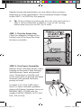
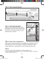
USER’S MANUAL For AC-Powered Fence Controllers Part I: Fence Controller Installation Before You Start . . . . . . . . . . . . . . . . . . . . . . . . . . . p. 2 Fence Controller Installation . . . . . . . . . . . . . . . . . . . . . p. 4 Fence Controller Operation . . . . . . . . . . . . . . . . . . . . . p. 10 Model 8200 Installation/Operation . . . . . . . . . . . . . . . . . p. 11 Part II: Electric Fencing Basics Electric Fence Components . . . . . . . . . . . . . . . . . Electric Fencing Basics . . . . . . . . . . . . . . . . . . . Grounding System . . . . . . . . . . . . . . . . . . . . . Fence Posts . . . . . . . . . . . . . . . . . . . . . . . . . Insulators . . . . . . . . . . . . . . . . . . . . . . . . . . Fence Wire . . . . . . . . . . . . . . . . . . . . . . . . . Gate Openings . . . . . . . . . . . . . . . . . . . . . . . Lightning/Surge Protection . . . . . . . . . . . . . . . . . Electric Fence Design . . . . . . . . . . . . . . . . . . . . Testing/Troubleshooting . . . . . . . . . . . . . . . . . . Fence Controller Warranty . . . . . . . . . . . . . . . . . USmanual-AC.indd 1 p. 12 p. 14 p. 15 p. 17 p. 19 p. 20 p. 22 p. 23 p. 25 p. 30 p. 33 SAVE THESE INSTRUCTIONS 6/24/2010 4:30:04 PM Before You Start All Zareba brand pulse-type electric fence controllers meet Underwriters Laboratories (UL) standards for safety. WARNING: Read ALL these instructions. Only use electric fence controller products for the purpose intended as defined in this manual. WARNING: Never run more than one fence controller on the same fence line at one time. The pulse time between the fence controllers will be too close together and could be hazardous to animals and people. It could also damage your fence controllers. WARNING: Install fence lines powered by separate fence controllers far enough apart to prevent contact with both fence lines at the same time. Simultaneously touching two fences powered by separate energizers could be hazardous. WARNING: In brushfire-prone areas, turn the fencer off on extremely dry days. For backup, be sure others know how to disconnect the fence controller. Also, never disconnect wires or approach a fence during lightning storms. WARNING: Do not operate fence controllers near any combustible materials including gasoline, kerosene and cleaning fluids. WARNING: Never electrify barbed wire or similar fence types where an animal or human may become tangled in the fence or caught against the fence. WARNING: To reduce risk of electrical shock, do not remove the fence controller cover. Refer to service personnel. USmanual-AC.indd 2 -2- 6/24/2010 4:30:05 PM WARNING: Check local zoning laws for electric fencing guidelines in your area. Also check with local utilities before digging to identify any buried cables or natural gas lines. In a double-insulated controller, two systems of insulation are provided instead of grounding. No means of equipment ground is provided in the supply cord of a double-insulated controller, nor should a means for equipment grounding be added to the controller. Servicing of a double-insulated controller requires extreme care and knowledge of the system, and should be done only by qualified service personnel. Replacement parts for a double-insulated controller must be identical to the parts they replace. Tools Required • Wire cutter/stripper (part no. FWC-1) • Flathead and phillips screwdrivers • Adjustable wrench • Voltage tester (part no. DEFT-1 or RSVT8) Other Required Components • Two lengths of 20 KV insulated hook-up wire (one long enough to connect fence controller to ground system and one long enough to connect fence controller to fence line) • Fence line connector (part no. 07110-96 for steel or poly wire; PRS2 for poly rope; or PTCC1 for poly tape) • 6- to 8-foot ground rod(s) (part no. GR8 or 07104-96) • Ground rod clamps–one per ground rod (part no. CGR1 or 07105-96) USmanual-AC.indd 3 -3- 6/24/2010 4:30:06 PM USmanual-AC.indd 4 Fence Controller Installation Overview of Installed Fence Controller Fence connection AC power plug Ground connection -4- 6/24/2010 4:30:06 PM STEP 1: Mount Fence Controller IMPORTANT: Mount inside or in a waterproof enclosure To fence Plastic/PVC pipe To ground Outdoor sheltered installation Inside installation Single screw mounting Double screw mounting USmanual-AC.indd 5 -5- 6/24/2010 4:30:08 PM STEP 2: Connect Ground and Fence Terminals USmanual-AC.indd 6 Your fence controller will have one of three types of terminals – strip wire and connect as shown below 1½“ 20KV hook-up wire – or – – or – Connect hook-up wire to GROUND terminal Connect hook-up wire to FENCE terminal -6- 6/24/2010 4:30:11 PM STEP 3: Connect to Ground System Ground rod clamp (part no.07105-96 or CGR1) Hook-up wire to other ground rods Hook-up wire from fence controller Ground rod (part no.07104-96 or GR8) NOTE: Connect additional ground rods with hook-up wire and ground rod clamps Check ground system reliability • IMPROPER GROUNDING WILL AFFECT THE PERFORMANCE OF YOUR FENCE CONTROLLER! See page 15 for more information about proper grounding. Tip: The fence controller must be grounded sufficiently for the system to work effectively. Improper grounding can also cause interference on telephone lines, radios and television and could invalidate your warranty. USmanual-AC.indd 7 -7- 6/24/2010 4:30:11 PM STEP 4: Connect to Fence Line Aluminum/Steel/Poly wire connection Galvanized line clamp (part no. 07110-96) Poly tape connection Poly tape connector clamp (part no. PTCC1) Poly rope connection USmanual-AC.indd 8 Poly rope splicer (part no. PRS2) Check fence system reliability • IMPROPER CONNECTION POINTS WILL AFFECT THE PERFORMANCE OF YOUR FENCE CONTROLLER! • Make sure splices and insulators are sound and secure. -8- 6/24/2010 4:30:12 PM STEP 5: Power Fence Controller NOTE: Fence controller will be outputting voltage at this point – to avoid shock do not touch fence terminal or fence wire. WARNING: For AC-powered fence controllers; do not modify the plug provided with the controller if it doesn’t fit into the outlet. Contact a qualified electrician for proper outlet installation. To reduce the risk of electric shock, these fence controllers have a polarized plug (one blade is wider than the other). This plug will fit in a polarized outlet only one way. If the plug does not fit fully in the outlet, reverse the plug. If it still does not fit, contact a qualified electrician to install the proper outlet. Do not change the plug in any way. USmanual-AC.indd 9 -9- 6/24/2010 4:30:13 PM Fence Controller Operation Fence OK • flashes when voltage is on fence line Fence OK • flashes 40-60 times/minute when voltage output is OK • flashes at slower rate when fence line voltage is low USmanual-AC.indd 10 Ground terminal • connect to ground rod Fence terminal • connect to fence line - 10 - 6/24/2010 4:30:14 PM Model 8200 Installation/Operation The 8200 (Cow Trainer) is used in stanchion-style dairy barns to train cows to defacate in the gutter. This fence controller powers the T-bar that hangs over the cow’s back, preventing them from hunching. Follow installation steps 1–5 as shown in previous pages. High/Low switch • use HIGH setting for increased voltage when training cows • use LOW setting for cows that are trained USmanual-AC.indd 11 HIGH OFF LOW 8200-A Cow Trainer Electric Fence Controller - 11 - 6/24/2010 4:30:15 PM Electric Fence Components 1 Fence controller (page 4) 2 6 Gate openings (page 22) 3 7 USmanual-AC.indd 12 Ground system (pages 7 and 15) Fence posts (page 17) Lightning/ surge protection (page 23) - 12 - 6/24/2010 4:30:16 PM USmanual-AC.indd 13 5 Fence wire (page 20) 4 Insulators (page 19) - 13 - 6/24/2010 4:30:16 PM Electric Fencing Basics Electric fencing is an easy-to-install system for containing animals or keeping them out. A short, safe pulse of electricity creates a psychological barrier that trains animals to avoid the fence. In order for the animal to feel a shock, the voltage produced by the fence controller must penetrate the animal’s hair, hide and hoof. How Electric Fencing Works The system works when an animal provides an electrical path by touching the fence wire and the earth simultaneously. The electricity then passes through the animal, into the soil and back to the ground rods, which are connected to the fence controller. At that point the circuit is complete and the animal instantly receives an electrical shock. Tip: For permanent, high tensile fence installation instructions, refer to Zareba’s High Tensile Electric Fence Guide available at zarebasystems.com. USmanual-AC.indd 14 - 14 - 6/24/2010 4:30:18 PM 2 Grounding System Overview of Grounding System An effective ground system consists of: • (3) 6’ to 8’ ground rods (part no. 07104-96 or GR8) • (3) ground rod clamps (part no. 07105-96 or CGR1) • 20 KV insulated hook-up wire (part no. UGC50, UGC250, 1404-92 or 7090-92) Fence Controller Electric Fence Controller 20 KV insulated hook-up wire Ground rod clamps 6' 10 ' First ground rod must be driven within 20’ of fence controller. 10 ' Copper or galvanized metal ground rods driven 6’ deep, spaced 10’ apart. See page 7 for detail on connecting ground system. Tip: Watering or sprinkling the soil around the ground rods in dry weather will improve ground system performance. USmanual-AC.indd 15 - 15 - 6/24/2010 4:30:19 PM Grounding in Dry or Frozen Ground Fence controller Animal makes contact with BOTH hot and ground wire to recieve shock Hot fence wire Ground return wire Hot fence wire Standard ground system Additional ground rod every 1,300’ In dry, sandy or frozen soil a typical grounding system is insufficient because electricity can not flow back to the fence controller. To compensate, create a ground wire return system with one fence wire carrying electricity back to the fence controller’s ground terminal. Run the ground return wire between hot/electrified wires and drive a 6-foot galvanized steel or copper rod every 1,300 feet. Regardless of the soil conditions, when the animal contacts the hot and ground wires simultaneously, they will feel a shock. Tip: Because the animal must contact the hot and ground return wire SIMULTANEOUSLY, we recommend these two wires be spaced within two to three inches of each other. WARNING: Do not install ground rods within 50 feet of a utility ground rod, buried telephone line or buried metal water line, as they may pick up stray voltage. Ground Installation Buried Ground Installation AroundAround Buried Metal USmanual-AC.indd 16 Metal Fence Controller Utility ground Water tank 50 ' Ground rods Water pipeline (or other buried metal) - 16 - 6/24/2010 4:30:23 PM 3 Fence Posts Fence posts fall into two categories: corner/gate posts, which must withstand tension; and line posts, which simply support the fence line between corner/gate posts. Post material varies and should be selected by fence type. Electric fencing will usually use fewer posts than conventional barbed or woven-wire fencing, making it less expensive and easier to install. Most posts are spaced 12–20 feet apart depending on terrain and animal being controlled. Post Spacing on Hilly Terrain Posts should be perpendicular to the slope of the terrain Don’t try to space posts evenly. In level terrain, posts can be spaced farther apart; for uneven terrain, a post should be placed at high and low points; and on hillsides, posts should be installed perpendicular to the slope. This keeps the wire at the proper height and prevents it from binding on insulators or clips. USmanual-AC.indd 17 - 17 - 6/24/2010 4:30:26 PM Post Selection Guide Post Type: Wood Post Plastic Step-in Post Steel T-post, U-post, Y-post Fiberglass T-post/ Rod Post Metal Rod Post X X X X X X Used for: Corner Posts X Line Posts X X X (limited) X Use With Fence Type: X Portable Semi- Permanent X Equine X Permanent High Tensile X USmanual-AC.indd 18 X X X X - 18 - 6/24/2010 4:30:26 PM 4 Insulators Insulators isolate the electric fence wire(s) to prevent shorting and electric current leakage, while also keeping the wires properly spaced. Select your insulators to fit the type of post and fence wire you are using. We recommend Red Snap’r® plastic insulators designed for every type of post – wood, T-posts, rod, corner, or chain link fencing. These insulators are available with various front ends to accommodate your selection of steel or poly wire, poly tape or poly rope. Tip: To prevent energy drain, routinely check to ensure insulators are clear of cobwebs and that electrified wires do not touch posts. Installation of Corner/End Post/Gate Insulators USmanual-AC.indd 19 End post/ gate insulator Corner insulator Staple Electric fence wire Staple Electric fence wire Nonelectrified wire Nonelectrified wire - 19 - 6/24/2010 4:30:27 PM 5 Fence Wire Electric fence wire carries the electrical current from the fence controller around the perimeter of the fence. Galvanized steel and aluminum wire carry electricity best. Poly wire, tape and rope have strands of conductive wire twisted or woven into the fabric and are ideal for electric fencing because of its ease-of-use, light weight and visibility. Tip: For equine enthusiasts, we recommend using 1½ inch white poly tape or ¼ inch white poly rope. They are highly visible, easy to install and safer than steel wire for horses. The height and spacing of the wires will vary with the animal being contained (or kept out). Always position one electrified wire at the animal’s shoulder height; the animal will hit the fence with its nose, making it back up. Proper spacing of the wires for the animal controlled is more important than overall fence height. Proper Wire Height and Spacing When installing fence wire, pull wire taut to maintain the same height and spacing between the posts. Tip: To prevent energy drain, keep electric fence wire clear of vegetation or objects touching the fence line. USmanual-AC.indd 20 - 20 - 6/24/2010 4:30:28 PM To maximize power on the fence, good electrical connections and splices are critical. Splicing Techniques Metal Wire Step 1 Never use loose or single-wrap splices Step 2 Poly Wire Tie any simple knot such as a square knot. Strip back and cut poly strands leaving two inches of conductive wires exposed. Twist or “pigtail” wires together. Poly Rope (using part no. PRS2) Stagger ends of poly rope and tightly secure using poly rope splicer. Poly Tape (using part no. SBS4 or SBL4) Step 1 Make one-foot loop. USmanual-AC.indd 21 Step 2 Insert poly tape through center of buckle and slip closed end over the upright flange. Step 3 Pull poly tape tight and over flange. - 21 - 6/24/2010 4:30:28 PM 6 Gate Openings Gate openings can be installed a variety of ways. Typically the same fence wire is used across the opening. If a metal gate or spring gate is used, 20 KV insulated hook-up wire should be used to carry the electrical current under the gate opening. NOTE: Refer to page 8 for information on how to make fence line connections. Standard Gate Installation 20KV insulated hook-up wire Line clamps Spring Gate Installation + Hot + Hot Metal Gate Installation + Hot + Hot + Hot + Hot + Hot + Hot USmanual-AC.indd 22 - 22 - 6/24/2010 4:30:34 PM 7 Lightning/Surge Protection Lightning is one of the main causes of fence controller failure. If a storm is forecast, disconnect your fence controller from the fence in advance, and unplug if it is an AC-powered unit. Using a Zareba Cut-Off Switch (part no. COS1) is a simple way to quickly disconnect your fence controller. If you are in an area with frequent electrical storms, be sure to keep a spare fence controller for backup. WARNING: Never disconnect a fence controller or approach an electric fence during a lightning storm. WARNING: Risk of electric shock! Do not connect an electric fence to any other device such as a cattle or poultry trainer, as lightning striking a fence will be conducted to other devices. Zareba offers several products designed to help minimize damage from lightning: Lightning Constrictor (part no. LC1) – A combination lightning diverter and lightning choke that installs between the fence line and the fence controller. Lightning Arrestor/Lighting Diverter (part no. LA1/07106-96) – Helps protect fence controller from lightning by diverting strike into the ground. USmanual-AC.indd 23 - 23 - 6/24/2010 4:30:35 PM Storm Guard (part no. 01667-92) – Helps protect fence controllers rated at 1 joule of energy output or greater from lightning strikes. Spring Gate Kit (part no. SG1) – Spring coil helps to dissipate lightning surges. AC Surge Suppressor (part no. 1549-96) – Protects AC-powered fence controllers from power surges up to 6,000 volts. Tip: While lightning protection devices can reduce damage by up to 75%, no device provides 100% protection from lightning. USmanual-AC.indd 24 - 24 - 6/24/2010 4:30:36 PM Electric Fence Design Design Your Fence Now that you understand how each component works in your fence, sketch your fence layout to get a count of materials you’ll need, including number of posts, wires, insulators, gate openings, etc. Tip: An electric fence line does not have to be constructed in a continuous loop; it also works effectively when dead-ended. Fence controller Corner posts Barn USmanual-AC.indd 25 Pond Gate Line posts - 25 - 6/24/2010 4:30:37 PM Estimate Your Electric Fence Supplies Use the chart below to get a rough idea of what you’ll need for different size enclosures. Tip: Visit zarebasystems.com to use our online Fence BuilderTM. It will recommend the correct products in the correct amounts for your electric fence. 5 Acres 10 Acres 528’ 330’ Total = 2,706’ 825’ 660’ Total = 1,980’ For a SINGLE wire fence with ONE gate opening: Posts (15ft spacing) Line Post Insulators (25/bag) Corner Post Insulators (10/bag) Poly wire, tape or rope (1,320ft spool) Gate handle kit 133 182 6 bags 8 bags 1 bag 1 bag 2 spools 3 spools 1 kit 1 kit For a THREE wire fence with ONE gate opening: Posts (15ft spacing) Line Post Insulators (25/bag) Corner Post Insulators (10/bag) Poly wire, tape or rope (1,320ft spool) Gate handle kit USmanual-AC.indd 26 133 182 16 bags 22 bags 2 bag 2 bag 5 spools 7 spools 1 kit 1 kit - 26 - 6/24/2010 4:30:37 PM Fence Configurations By Species Tip: Electric fence systems can be built in any configuration as needed by the end user. The following pages show recommended voltage levels and wire spacings to safely contain different species. Voltage for Cows: 2,000–3,000 v Voltage for Bulls: 3,000–4,000 v • docile cattle require fewer strands; determined bulls require 4-wiremore voltage 3-wire 40" total 5-wire 52" total 6-wire 42" total 10" 10" 10" 10" 8" 10" 6" 10 " Boundary fences 32"– 42” total 6" 10" 20" 1-wire 6" 12" Feed lots 6" Deter predators Portable/temporary fences Voltage: 2,000–3,000 v • high visibility for safety; use white 1½” poly tape 3-wire 40" total 4-wire 46" total 5-wire 52" total 10" 10" 10" 10" 10" 10 " 10" 10" 1-wire 36"– 48” total 10" 20" Geldings and mares USmanual-AC.indd 27 16" 12" Mares and colts Stallions Portable/temporary fences - 27 - 6/24/2010 4:30:39 PM Voltage: 4,000–5,000 v • thick coats/determined animals require more voltage; 4-wire may need to deter predators 7-wire 70" total 6-wire 42" total 10" 10 " 10" 8" 10" 6" 10" 6" 10" 6" 10" 6" 10" Less space between wires deters predators Taller fence to deter goats jumping Voltage: 4,000–5,000 v • determined animals looking for food need 4-wire higher voltage 6-wire 42" total 10" 18"– 24” total Portable/ temporary fences Voltage: 1,000–2,000 v • wires need to be low to ground to deter rooting 4-wire 7-wire 70" total 3-wire 24" total 10" 10" 10 " 8" 10" 6" 10" 6" 10" 6" 10" 6" 10" 6" Taller fence to deter jumping Boundary fences Less space between wires deters predators USmanual-AC.indd 28 1-wire 8" - 28 - 6/24/2010 4:30:40 PM Voltage: 1,000–2,000 v • smaller animals require closer wire spacing and 4-wire wire close to ground Voltage: 700–1,000 v • use to contain/deter or prevent jumping or 4-wire digging 5-wire 16" total 24" total 6" 4" 6" 3" 3" 6" 3" 6" 3" Height/number of wires depends on size of animal Height/number of wires depends on size of animal Voltage: 4,000–5,000 v • easily trained, but thick coats require 4-wire more voltage 4-wire 46" total 6-wire 42" total 10" 10" 10 " 8" 10 " 16" Boundary fence USmanual-AC.indd 29 Retrofit existing fence with wire at top/bottom Voltage: 4,000–5,000 v • higher voltage needed; fence needs to deter 4-wire jumping/reaching under 15-wire 72" total 6" 8" spacing 4" spacing 6" 6" 6" Deter predators Boundary fences - 29 - 6/24/2010 4:30:42 PM Testing/Troubleshooting 1 Test fence line voltage regularly at the furthest point on the fence from the fence controller to ensure voltage is adequate for the animal being controlled. Adequate voltage reading – fence line OK 2 Inadequate voltage Ensure power supply is sufficient (battery/AC power) Replace/repair battery or AC power to fence controller If power OK, disconnect FENCE and GROUND wires from fence controller, then check voltage output by touching metal part of terminals with tester. If output is normal (over 5,000 volts*), reconnect FENCE/GROUND wires If output is less than 5,000 volts* there is a fence controller fault. Call Zareba for assistance. * (2,000 volts for models 10ACRE, 20 ACRE, ACC2, 33C, RS3 or SP3) 3 Test ground system – it should read less than 400 volts on ground rod. If over 400 volts, add extra ground rods or make them deeper. Test again/add more ground rods until ground system reads under 400 volts. Remember grounding is affected by soil conditions. 4 If grounding is OK, test the hook-up wire that connects the fence controller to the fence line. Disconnect hook-up wire from fence line and test. Under 4,500 volts* Hook-up wire is leaking to ground. Ensure you are using 20 KV insulated hook-up wire. Replace and recheck. Over 4,500 volts* Turn off fence controller and reconnect the hook-up wire to fence line. * (1,500 volts for models 10ACRE, 20 ACRE, ACC2, 33C, RS3 or SP3) 5 Check fence line Poor hook-up wire connections Poor jumpers between lines Poor fence line splices/ conductors Fence line short or leak to ground Leaking hook-up wire under gateway Very heavy vegetation against the fence line Metal object touching fence line Bad or incorrect insulator Fence line touching a fence post Faulty connections at gate openings USmanual-AC.indd 30 If you cannot resolve the problem please call Zareba Systems at 800-800-1819. - 30 - 6/24/2010 4:30:43 PM Regular testing and maintenance of your electric fence system is important to assure performance. We recommend Zareba voltage testers DEFT-1 or RSVT8 for this purpose. Tip: Testing voltage by touching the fence line with your hand or a weed is not recommended. In addition, if you do this wearing rubber-soled shoes you will NOT feel a shock. STEP 1: Test the Fence Line Check for adequate voltage at the furthest end of the fence line from the fence controller. STEP 2: Test Fence Controller Remove fence controller power source (unplug or disconnect from battery) and disconnect fence and ground wires. Power fence controller and touch metal bolts of ground and fence terminals with ground and fence prongs of tester. Electric Fence Controller If output is less than 5,000 volts*, there is a fence controller problem – please call Zareba Customer Service at 800-800-1819. (*2,000 volts for models 10ACRE, 20ACRE, ACC2, 33C, RS3, SP3 or LIS3) USmanual-AC.indd 31 - 31 - 6/24/2010 4:30:45 PM STEP 3: Test Ground System To fence controller (FENCE terminal) 100 yards Push probe into ground Short the fence using a metal bar or wire To fence controller (GROUND terminal) Touch ground rod with tester. If reading is over 400 volts, grounding is inadequate. Add additional ground rods 6 feet apart connected by hook-up wire until reading is under 400 volts. To FENCE terminal STEP 4: Test Hook-Up Wire Remove fence controller power source (unplug or disconnect from battery) and disconnect hook-up wire from fence line. Power fence controller and then check hook-up wire as shown. Touch tester contacts to hook-up wire. STEP 5: Check Fence Components Walk your fence line and inspect all components. Insulators should be clean and not cracked. Fence wire should be properly spliced, not touching fence posts and properly connected at all points. Verify weeds, branches or other debris are not touching the fence line. STEP 6: If you are still getting inadequate voltage readings visit ZarebaSystems.com for further tips or call Zareba Systems customer service at 800-800-1819. USmanual-AC.indd 32 - 32 - 6/24/2010 4:30:46 PM Fence Controller Warranty 30-DAY FULL WARRANTY Zareba Systems® guarantees your satisfaction. You can return product with its receipt to the place of purchase within 30 days for a full refund. Proof of purchase is required for a full refund. LIMITED WARRANTY This fence controller is warranted for one year from the date of sale to be free from defects of material and workmanship and from damage caused by lightning. Fencers that are equipped with the Storm Guard lightning protection module are warranted only when the Storm Guard is properly installed on the fence controller. Proof of purchase is required for warranty consideration, and may be returned to Zareba Systems® or any of the Zareba Authorized Repair Centers for warranty repair. If no sales receipt has been returned, the date of manufacture will be used to determine the warranty period. Neither the full or limited warranty applies to any defect in the product caused by improper installation, misuse, tampering, neglect, moisture or any other reason not related to defects in material or workmanship of the product. The full and limited warranties are not assignable or transferable. It is for the benefit of and given only to the first consumer purchaser of the product, and shall not be for the benefit of nor given to any subsequent owners or any other user or to any person. The obligation of Zareba Systems® under the limited warranty is only to repairing or replacing, at its option, any part of the product that is defective and is covered by the terms of this warranty. If any covered defect occurs during the warranty, return the product for replacement or repair, with freight prepaid, to any Authorized Repair Center or directly to Zareba Systems®, 69 N. Locust Street, Lititz, PA 17543. There will be no further cost to you if it is a result of defects, failures or malfunction of the product. (Note: The following fence controller models can only be returned to the factory for warranty consideration: 601, 8574, A5, WD56, 30, 10 ACRE, 20 ACRE, 415, 410, 4444, 4612, 4465, 4309, 8565, 8555, 8612, 77, 98, S12, S100, 980, 57, S12, TCC2, ACC2 and 33B. Any model of fence controller not listed can be sent to any Authorized Repair Center or to the factory). UPON EXPIRATION OF THE FULL 30-DAY WARRANTY, ZAREBA SYSTEMS® MAKES NO OTHER EXPRESSED OR IMPLIED WARRANTIES OF FITNESS OR MERCHANTABILITY OR ANY OTHER WARRANTIES, EITHER EXPRESSED OR IMPLIED; ANY IMPLIED WARRANTY OF MERCHANTABILITY OR FITNESS FOR A PARTICULAR PURPOSE, WHICH EXCEEDS THE FOREGOING WARRANTY, IS HEREBY DISCLAIMED BY ZAREBA SYSTEMS®. THERE ARE NO WARRANTIES WHICH EXTEND BEYOND THE DESCRIPTION OF THE FACE HEREOF. Some states do not allow limitations on how long an implied warranty lasts, so the above limitation may not apply to you. In no case shall Zareba Systems® be liable for incidental, consequential, special or indirect damages of any kind. Any action for breach of warranty must be started within one year after the cause of action shall occur, and no such action shall be maintained which is not commenced within such a period. Some states, however, do not allow the exclusion or limitation of incidental or consequential damages, so the above limitation or exclusion may not apply to you. This limited warranty gives you specific legal rights, and you may also have other rights which vary from state to state. If you have any questions about how to exercise your rights under the terms of either the full or limited warranty, you may call Zareba at 800-800-1819, email to [email protected] or write to Zareba Systems®, 69 N. Locust Street, Lititz, PA 17543. USmanual-AC.indd 33 - 33 - 6/24/2010 4:30:46 PM LIMITATION OF DAMAGES The directions for use of this product should be followed carefully. It is impossible to eliminate all risk inherently associated with use of the product. The effectiveness of Zareba Systems® brands of fence controllers may depend on the effectiveness of connections, interruption of power source, accidental grounding of wires, weather conditions, or the manner of use or application, all of which are beyond the control of Zareba Systems® or the seller. All such risks shall be assumed by the buyer. Zareba Systems® warrants that this product is reasonably fit for the purposes referred to in the directions for use, subject to the inherent risks referred to above. Zareba Systems® makes no other expressed or implied warranty of fitness or merchantability or any other expressed or implied warranty. IN NO CASE SHALL ZAREBA SYSTEMS® OR THE SELLER BE LIABLE FOR CONSEQUENTIAL, SPECIAL OR INDIRECT DAMAGES RESULTING FROM THE USE OR HANDLING OF THIS PRODUCT. ZAREBA SYSTEMS® AND THE SELLER OFFER THIS PRODUCT AND THE BUYER AND USER ACCEPT IT, SUBJECT TO THE FOREGOING CONDITIONS OF SALE AND WARRANTY WHICH MAY BE VARIED ONLY BY AGREEMENT IN WRITING SIGNED BY AN OFFICER OF ZAREBA SYSTEMS®. Some states, however, do not allow the exclusion or limitation of incidental or consequential damages, so the above limitation or exclusion may not apply to you. This limited warranty gives you specific legal rights, and you may also have other rights which vary from state to state. USmanual-AC.indd 34 - 34 - 6/24/2010 4:30:46 PM USmanual-AC.indd 35 6/24/2010 4:30:46 PM USmanual-AC.indd 36 Woodstream Corp. 69 N. Locust Street Lititz, PA 17543 Contact us: ZarebaSystems.com [email protected] 800-800-1819 Part # 0077368-004 Rev10 6/24/2010 4:30:48 PM