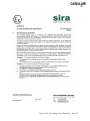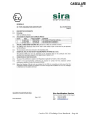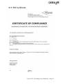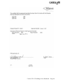
1
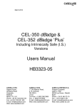
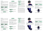
June 2011
CEL-35x dBadge
Including Intrinsically Safe (I.S.)
Versions
Users Manual
HB3323-07
CASELLA CEL
Regent House,
Wolseley Road,
Kempston,
Bedford,
MK42 7JY, U.K.
Phone: +44 (0) 1234 844 100
Fax: +44 (0) 1234 841 490
E-mail: [email protected]
Web: www.casellameasurement.com
CASELLA USA
17 Old Nashua Road #15
Amherst, NH 03031-2839,
U.S.A.
Toll Free: +1 (800) 366 2966
Fax: +1 (603) 672 8053
E-mail: [email protected]
Web: www.casellaUSA.com
CASELLA ESPANA S.A.
Polígono Európolis
Calle C, nº4B
28230 Las Rozas - Madrid
Spain
Phone: + 34 91 640 75 19
Fax: + 34 91 636 01 96
E-mail: [email protected]
Web: www.casella-es.com
Casella CEL-35X dBadge Users Handbook – Page 1
Caution
UNDER NO CIRCUMSTANCES should this equipment be cleaned
using a solvent based cleaner.
The CEL-35X dBadge contains no user serviceable parts, do not open
product case as this would invalidate the warranty.
When in use, always use the windshield provided.
Use only the recommended CEL-252 microphone.
Damage caused by a failure to observe these warnings will NOT be
covered by the normal warranty conditions.
When using the CEL-6351 pin mounting clips, care should be taken
when fitting them to an employee so that the skin is not pierced
accidentally.
Please refer to section 6.2 of this manual when changing dBadge
mounting clips as placing the incorrect screw in the wrong hole can
damage the dBadge.
Environmental Considerations
Do not dispose of electronic equipment as municipal waste
The WEE symbol shown above indicates that separate
collection systems should be used
Casella CEL-35X dBadge Users Handbook – Page 2
Instructions specific to hazardous area installations
(reference European ATEX Directive (94/9/EC, Annex II, 1.0.6.)
The following instructions apply to equipment covered by certificate
number Sira 07ATEX2032X for the CEL-35X/IS dBadge series:
The certificate number includes an „X‟ suffix indicating that the
following special conditions of certification apply;
1. Parts of the enclosure are non-conducting and may generate an
ignition–capable level of electrostatic charge under certain
extreme conditions. The user should ensure that the equipment
is not installed or used in a location where it may be subjected to
external conditions (such as high-pressure steam), which might
cause a build-up of electrostatic charge on non-conducting
surfaces. Additionally, cleaning of the equipment should be
done only with a damp cloth.
2. The dBadge Noise Dosemeter shall not be used in areas where
a layer of coal dust may be deposited on the enclosure.
3. The microphone should not be removed in a hazardous area.
4. The equipment may be used with flammable gases and vapours
with apparatus Groups IIA, IIB and IIC and with temperature
classes T1 and T2.
5. The equipment is only certified for use in ambient temperatures
in the range -20oC to +40oC and should not be used outside this
range.
6. Repair of this equipment shall only be carried out by the
manufacturer or in accordance with the applicable code of
practice.
7. If the equipment is likely to come into contact with aggressive
substances, then it is the responsibility of the user to take
suitable precautions that prevent it from being adversely
affected, thus ensuring that the type of protection is not
compromised. Aggressive substances e.g. solvents may affect
polymeric materials.
8. Do not charge the batteries in a hazardous area. Only charge
the CEL-35X or CEL-35X/IS using the recommended charger
CEL-6362.
9. The CEL-120/2 must only be used to calibrate the CEL-35X or
CEL-35X/IS in a non-hazardous atmosphere.
Casella CEL-35X dBadge Users Handbook – Page 3
CONTENTS
1 INTRODUCTION .................................................................................................... 5
2 SUPPLIED EQUIPMENT....................................................................................... 6
3 THE SYSTEM COMPONENTS ............................................................................ 8
3.1 The CEL-35X dBadge ......................................................................................... 8
3.2 Mounting Clips .................................................................................................... 8
3.3 The CEL-6362 Charger ....................................................................................... 9
3.4 The Windshield ................................................................................................. 10
4 CHARGING THE CEL-35X ................................................................................. 11
4.1 Charging ............................................................................................................ 11
4.2 Linking Chargers Together ............................................................................... 12
5 GENERAL OPERATION ..................................................................................... 13
5.1 Switching on the dBadge ................................................................................... 13
5.2 Calibration ......................................................................................................... 14
5.3 Starting A Measurement Run ............................................................................ 16
5.4 Stopping A Measurement Run .......................................................................... 19
5.5 Reviewing Measurement Run Data ................................................................... 20
5.6 Configuration Menu .......................................................................................... 22
5.7 Display Mode .................................................................................................... 25
5.8 Alarm Settings ................................................................................................... 26
6 MOUNTING THE CEL-35X ................................................................................ 28
6.1 CEL-6351 Pin Mounting Clips.......................................................................... 28
6.2 CEL-6352 Crocodile Clip Mounting Kit........................................................... 29
6.3 CEL-6353 Harness Mounting Kit ..................................................................... 30
6.4 CEL-6354 Hard Hat Mounting Kit ................................................................... 30
7 TECHNICAL SPECIFICATION ......................................................................... 31
7.1 Specification ...................................................................................................... 31
7.2 Microphone Specification (CEL-252) ............................................................... 32
8 SERVICING AND WARRANTY ARRANGEMENTS ..................................... 33
9 TROUBLESHOOTING ......................................................................................... 34
10 APPENDIX ........................................................................................................... 35
10.1 Glossary of Terms ........................................................................................... 35
10.2 Measured Parameters....................................................................................... 39
10.3 Using the CEL-352 for the Selection of Hearing Protection ........................... 40
10.4 ATEX Certificate ............................................................................................ 42
10.5 FM Certificate ................................................................................................. 45
Casella CEL-35X dBadge Users Handbook – Page 4
1 INTRODUCTION
The CEL-35X family consists of the CEL-350 dBadge, CEL-350L
dBadge „Lite‟ and the CEL-352 dBadge „Plus‟. The CEL-35X dBadge
is a unique solution to problems associated with the measurement of
personal noise exposure. Using the latest digital technology ensures
reliable and repeatable measurements. The CEL-35X dBadge has no
cable like a traditional dosimeter, so is far easier to fit to an employee
and is less likely to interfere with the individuals work. Casella CEL
provides various mounting options for the dBadge.
The CEL-35X dBadge is very simple operate with just 2 keys, and can
be locked to prevent tampering. After a measurement has been
completed the noise badge can be downloaded via it‟s infra-red port to
the Casella insight data management software. This will allow
comprehensive analysis of an employee‟s exposure.
This manual describes the operation of the CEL-35X dBadge and the
associated mounting options, as well as charging the dBadge.
Use of the CEL-35X/IS Intrinsically Safe (I.S.) dBadge is described,
including special requirements for use under ATEX certification.
The CEL-350L is an entry level model that does not store the time
history of the noise data.
The CEL-352 dBadge „Plus‟ measures additional values which allow
for the selection of hearing protection via the Single Number Rating
(SNR) or High, Medium, Low (HML) methods.
Casella CEL-35X dBadge Users Handbook – Page 5
2 SUPPLIED EQUIPMENT
Carefully remove all components of the dBadge from the shipping
container and check for possible damage or any missing items. If any
items are not present or damaged please contact Casella CEL
immediately. The following components should be included:
CEL-35X
Or
CEL-35X/IS
dBadge (includes microphone CEL-252, windshield
CEL-6356 and calibration certificate)
I.S. dBadge (includes microphone CEL-252,
windshield CEL-6356 and calibration certificate)
Where CEL-35X represents either a CEL-350 or CEL-352
CEL-6351
CEL-6352
Pin Mounting Kit
Crocodile Clip Mounting Kit (fitted to CEL-35X)
Instrument kits include the following parts:
HB-3323
HB-3324
CEL-6362
CEL-6355
CEL-120/2
193200B
CEL-6357
-HK111
dBadge Instruction Manual (on CEL-6357 software
CD)
Field Guide (printed hard copy)
3-way Charger Unit (including -PC18 Power Supply
Unit)
Kit Case for up to 10 dBadge Units
Class 2 Acoustic Calibrator (including calibration
certificate)
Infra Red Download Cable (includes screwdriver)
Casella insight data management software on CD
including HB-3325 Software Manual and HB-3323
dBadge Manual
Screwdriver for changing mounting clips
If a kit with 10 dBadges was purchased, the following item will
be present:
CEL-6363
3-way charger extension unit (including C6359/0.2
cable)
Casella CEL-35X dBadge Users Handbook – Page 6
Optional items at time of order:
D8147/Z
CEL-6351
CEL-6352
CEL-6354
CEL-6356
CEL-90336
3 Point Harness
Spare Pin Mounting Kit (5 Pack)
Crocodile Clip Mounting Kit (5 Pack)
Hard Hat Mounting Kit
Spare Windshield
USB Adaptor
Casella CEL-35X dBadge Users Handbook – Page 7
3 THE SYSTEM COMPONENTS
3.1 The CEL-35X dBadge
The CEL-35X dBadge and controls are shown below in Figure 1. The
two controls are the Left (L) and the Right (R) keys.
Windshield
Left „L‟ Key
(Power Key)
Right „R‟ Key
LED
Window
Display
Figure 1
3.2 Mounting Clips
Upon delivery, the CEL-35X will be fitted with the CEL-6352
„Crocodile‟ mounting clips, as shown in Figure 2. Mounting clips can
be changed using the screwdriver provided. For information on
changing the mounting clips please see section 6.
Casella CEL-35X dBadge Users Handbook – Page 8
Crocodile
Mounting
Clips
Screws for
mounting
clips
Figure 2
3.3 The CEL-6362 Charger
A CEL-6362 is a drop-in intelligent 3-way charger unit, required to
charge the internal Nickel Metal Hydride (NiMH) batteries on the CEL35X dBadge. The CEL-6362 consists of the charger base, part
number 193102B-01 and the -PC18 mains power supply unit (PSU).
The PSU will require fitting with an appropriate plug connector
(supplied) for the country of use.
Figure 3
Note that charger base 193102B-01 is for use with the CEL-35X and
the CEL-35X/IS. The previous version of the charger base (193038B01) can only be used with the CEL-35X and NOT the CEL-35X/IS.
Casella CEL-35X dBadge Users Handbook – Page 9
Note that all versions of the dBadge should only be charged in nonhazardous areas in the absence of any flammable atmospheres.
3.4 The Windshield
During use, it is essential the dBadge is fitted with the CEL-6356
windshield (supplied). To calibrate the dBadge it is necessary to
remove the windshield to gain access to the microphone. To remove
the windshield, twist the black plastic ring below the foam anticlockwise and lift the windshield to remove.
Figure 4
Once the CEL-35X dBadge has been calibrated (section 5.2) refit the
windshield by placing the windshield back into the body of the dBadge
and twisting clockwise, as shown previously in Figure 4.
Casella CEL-35X dBadge Users Handbook – Page 10
4 CHARGING THE CEL-35X
4.1 Charging
The CEL-35X dBadge uses internal NiMH batteries. Ensure the CEL35X is fully charged prior to use by placing in the charger as shown in
Figure 5. Note the CEL-35X will fit into charger units regardless of
which mounting clips are attached.
Figure 5
Ensure the power supply (-PC18) is connected and the supply is
switched on. The CEL-35X dBadge will automatically switch on
during charging and display how much charge is within the dBadge,
as shown in Figure 6. When the CEL-35X dBadge is charging the
red LED will flash and the charge symbol
will rotate on the top right
of the display. The dBadge will display „Full‟ once charging is
complete and the LED on the front of the instrument will turn blue.
This should take approximately 1.5 hours from a discharged state. A
charging time of about 30 minutes will be sufficient to perform greater
than 8 hours of measurement. Once fully charged, the CEL-35X
holds enough charge to run for approximately 28 hours.
CHARGING
27Hrs
FULL
28Hrs
Figure 6
Casella CEL-35X dBadge Users Handbook – Page 11
Note that once removed from the charger, the dBadge will
automatically switch off. If returned to the charger the CEL-35X will
charge for a minimum time of 10 minutes regardless of whether it is
fully charged. This does not affect battery performance in any way. If
the battery is fully discharged prior to being placed on a charger, the
CEL-35X will be trickle charged for a short time prior to the fast charge
cycle, this prevents damage to the batteries. If this occurs a „PreCharge‟ message will appear on the dBadge display.
4.2 Linking Chargers Together
The main CEL-6362 charger can be linked to the CEL-6363 charger
extension unit via the C6359/0.2 cable supplied with the CEL-6363.
Up to 3 CEL-6363 units can be linked to the CEL-6362 charger for
charging up to 12 dBadge units as shown in Figure 7 below.
PC18
Power supply
CEL-6363 - Expansion charger kit
3 Way Charger + C6359/0.2 link cable.
CEL-6362 - 3 Way charger Kit
3 Way Charger + PC18 Power supply
.....x4 CHARGER BASES
IN TOTAL
Figure 7
Casella CEL-35X dBadge Users Handbook – Page 12
5 GENERAL OPERATION
5.1 Switching on the dBadge
Once the instrument is switched on by pressing the „L‟ key, it will
display a start up sequence, shown in Figure 8. This displays the
dBadge model number and firmware version (e.g. V1.07), followed by
the „Custom Text‟ screen. This text can be configured using the
Casella insight data management software. The screen will then
change to the current time and date. This will automatically be set to
the internal clock of the PC every time the dBadge is downloaded to
Casella insight data management software.
CASELLA
CEL-350
V1.01
Screen will show CEL350L on dBadge „Lite‟
model or CEL-352 on
dBadge „Plus‟ model.
JOE BLOGGS
CONSULTANTS
23 JUL 05
13:45:03
Figure 8
The next screen shows the remaining battery life and memory as
shown in Figure 9. The caution symbol
will be displayed on the left
of the display if remaining memory or battery life are under 2 hours.
The next screens show the instantaneous sound pressure level (SPL)
currently being measured by the microphone and the current clock
time set within the instrument.
7Hrs
80Hrs
13:45:03
LAF 112.3 dB
Figure 9
Casella CEL-35X dBadge Users Handbook – Page 13
The subsequent screens will cycle through results from the last
measurement run, as shown in Figure 10. Values shown will be
dependent on whether the CEL-35X is configured to display ISO or
OSHA parameters (see sections 5.6 & 5.7).
ISO VIEW
DURATION
07:45:12
LAEQ 89.9
LCPK 101.4
PA Hrs
3.20
PROJ DOSE
352.5 %
LAVG 111.4
LZPK 119.4
OSHA DOSE
114.3 %
PROJ DOSE
175.3 %
OSHA VIEW
DURATION
07:59:32
Additional screen on CEL-352 dBadge „Plus‟ model:
LCEQ 92.4 dB
LC-A 4.8 dB
Figure 10
Note: If „Pro Mode‟ is enabled additional menus will be displayed, see
section 5.5.
The over-range symbol
will be shown if the CEL-35X has been
exposed to noise over the linear operating range. The screens will
continue to automatically cycle through as shown in Figure 9 and 10
until another action is performed. Pressing the „R‟ key will stop the
screens cycling for 5 seconds. Screens can also be manually cycled
through by pressing the „R‟ key repeatedly. Note that if the memory is
currently empty the screens shown in Figure 10 will not be shown.
5.2 Calibration
It is important to calibrate each dBadge before and after use, in
accordance with workplace noise regulations. The dBadge records
calibration levels and times which can be viewed later on Casella
insight data management software.
Note that the dBadge will not enter calibration mode if a measurement
run is taking place. If a run is in progress, stop the run according to
section 5.4.
Casella CEL-35X dBadge Users Handbook – Page 14
The windshield should be removed prior to calibration, refer to section
3.4.
Push the CEL-120/2 acoustic calibrator over the microphone as
shown in Figure 11. The calibrator should be pushed on without
twisting.
Figure 11
The CEL-35X dBadge will automatically recognise a 1kHz calibration
tone is present and display the screen shown in Figure 12.
CALIBRATE ?
X 114.0
Figure 12
Press the „R‟ key to confirm you wish to calibrate the unit, it will take
a few seconds to calibrate automatically to 114.0dB, during which time
a progress bar will be displayed as shown in Figure 13.
Casella CEL-35X dBadge Users Handbook – Page 15
CALIBRATING
CAL. OK
114.0
Figure 13
Once the unit has successfully calibrated the „Cal OK‟ message will
appear. In the unlikely event an error message is displayed as shown
in Figure 14, please refer to „Troubleshooting‟ section.
CAL. ERROR
Figure 14
The CEL-35X is ready to take a measurement once the calibrator has
been removed.
NOTE: The CEL-120/2 must only be used to calibrate the CEL-35X/IS
in a non-hazardous atmosphere.
5.3 Starting A Measurement Run
Ensure the windshield is fitted according to section 3.4. The
windshield protects the microphone from any potential erroneous
results from wind, but also helps to protect from any dust ingress,
moisture or impact damage. Before taking a measurement run,
ensure there is sufficient battery life and memory by looking at the
screen shown in Figure 9. If necessary charge the dBadge as
described in section 4.1 and clear the memory as described in section
5.6, or download the dBadge to Casella insight data management
software.
Regardless of which display mode is selected (ISO or OSHA) ALL
parameters are stored simultaneously and can be viewed via Casella
insight data management software.
To start the measurement run, press and hold both the „L‟ and the „R‟
keys down together for 3 seconds as shown in Figure 15.
Casella CEL-35X dBadge Users Handbook – Page 16
Press and hold
for 3 seconds
Press and hold
for 3 seconds
Figure 15
When these keys are held down together the display on the dBadge
will begin a count down, as shown in Figure 16. The keys must be
held down during the countdown for the measurement run to begin.
START
3
START
2
START
1
Figure 16
will
Once the measurement run has begun, the „Play‟ symbol
appear in the top left of the screen. The display will cycle between 2
screens. The first displays instantaneous sound pressure level (SPL)
values and the duration of the measurement run so far. The second
displays the status of the memory and battery. The screens are
displayed below in Figure 17.
Casella CEL-35X dBadge Users Handbook – Page 17
LAF 112.3 dB
DUR 07:45:12
15Hrs
145Hrs
Figure 17
Casella CEL recommends the dBadge is locked to prevent the wearer
from tampering with the unit. To do this, press and hold the „R‟ key
whilst pressing the „L‟ key 3 times, as shown in Figure 18.
2. Press 3 times
1. Press and
hold
Figure 18
This will lock the keypad so any random presses of keys will not
accidentally effect the measurement. The display of the CEL-35X will
also change so as not to show any SPL values. This removes the
temptation to shout into the microphone, as it has no visual effect. A
will be shown in the bottom left of the screen to
padlock symbol
indicate the keypad is locked, as shown in Figure 19.
DURATION
07:55:12
Figure 19
To unlock repeat the process shown in Figure 18.
Note: If „Autolock‟ is enabled from configuration menu, (section 5.6)
the dBadge will automatically lock.
Casella CEL-35X dBadge Users Handbook – Page 18
If during a measurement run, the remaining battery or memory
capacity falls below 2 hours, the red LED will flash and the warning
icon will be shown on the display.
5.4 Stopping A Measurement Run
If the CEL-35X dBadge is locked, first unlock the keypad by holding
down the „R‟ key whilst pressing the „L‟ key 3 times, as shown in
Figure 18. To stop the measurement run, press and hold the two keys
simultaneously for the period of the countdown, as shown in Figure
20.
STOP
3
STOP
2
STOP
1
Figure 20
The display on the CEL-35X will then show the data from the
measurement run that has just been completed, as shown in Figure
21. A new measurement run can be started immediately by following
the steps described in section 5.3. Ensure enough battery life and
memory capacity remains if a consecutive measurement run is to be
performed.
Casella CEL-35X dBadge Users Handbook – Page 19
5.5 Reviewing Measurement Run Data
As soon as a measurement run has been stopped, the dBadge will
automatically display results from the completed measurement run.
The display will automatically cycle as shown in Figure 21. The
screen contents will depend upon which display mode is selected
(ISO or OSHA).
The last screen, highlighted in red, is only available on the CEL-352
dBadge „Plus‟ model
Figure 21
Casella CEL-35X dBadge Users Handbook – Page 20
If „Pro Mode‟ is enabled, screens shown in Figure 22 become
viewable. The screen contents highlighted in blue will depend upon
which display mode is selected (ISO or OSHA). To enable „Pro Mode‟
see section 5.6.
Figure 22
By pressing the „R‟ key when on any of these screens, the display will
stop cycling for a period of 5 seconds.
Casella CEL-35X dBadge Users Handbook – Page 21
On the CEL-352 dBadge „Plus‟, The LC-A is simply the LCeq minus the
LAeq for use in the HML method for the selection of hearing protection.
For detailed information on how to use these values to calculate the
effectiveness of hearing protection, please see section 10.3.
5.6 Configuration Menu
The configuration menu is accessed by holding the „R‟ key down
whilst switching on the dBadge („L‟ key), see Figure 23.
CONTRAST
English, French,
German, Italian,
Spanish, Portuguese
PRO. MODE
NO
Yes...No
DISPLAY MODE OSHA, ISO
ISO
Pro. Mode OSHA Only
THRESH
80+90dB
Yes...No
80dB ..90dB ..80+90dB
Pro. Mode Only
SCROLL LCD
NO
PRESET MODE Yes...No
NO
AUTO
SURE?
NO
Yes
NO
Yes...No
CLEAR MEMORY Yes...No
NO
Figure 23
Casella CEL-35X dBadge Users Handbook – Page 22
The first configuration screen to be displayed is the contrast menu.
For each option within these menus press the „L‟ key to adjust what
is on the screen then press „R‟ to confirm and move to next screen.
Contrast setting
You can adjust the display contrast for best viewing of the text on
screen. There are 6 different contrast levels available.
Language setting
You can select one of the pre-programmed languages that are
available. Currently these are English, French, German, Italian,
Spanish, and Portuguese.
Pro Mode setting
You can select to leave the Pro Mode disabled for simplicity of
displayed results or choose to enable it to show the calculated values
at the 80 + 90, 80 only or 90 only threshold levels. (or values of Lex8h
and Proj Lex8h)
Display mode setting
You can select either ISO or OSHA display modes for on screen
results but both settings are measured and stored for all runs so that
relevant data can be seen in the Casella insight data management
software program from every run.
For further details about the „Display Mode‟ see section 5.7.
Threshold setting
This menu is only displayed if the OSHA display mode is selected in
the previous step. You can select either both the 80 + 90, just the 80
dB (for the HCA) or just the 90 dB (for the PEL) on screen. The 80 +
90 setting gives the maximum number of displayed screens in the
instrument but if only the tighter HCA (or lower threshold settings) are
required for simplicity then select the 80 setting only. Similarly, if the
90 dB upper threshold is set then only the PEL results will be
displayed on screen. In any of these 3 cases it should still be
remembered that whatever the setting chosen here it will only affect
the displayed results and that all the data will be stored to calculate
every required parameter when downloaded to Insight software (and
dB35).
Casella CEL-35X dBadge Users Handbook – Page 23
Scroll LCD setting
You can choose to allow the display screens to scroll through as
described above or you can select to switch off this function and step
through the displayed dosimeter screens one by one manually.
dB Alarms setting
You can choose to enable or disable the high intensity blue flashing
LED when the measured noise levels exceed the set threshold trigger
levels chosen in the Casella insight data management software (or
dB35) configuration setup. For further details see section 5.8.
Pre-set Mode (Run Duration Timers)
This mode allows a variety of settings from Off through to 12:00 in 30
minute steps by pressing the left button to show the value required
and then pressing the right button to accept and move on to the next
menu item. Press and hold in the left button to change through the
selections more quickly. The run will start and run for the selected
fixed duration time chosen in this menu.
Auto Lock
This choice is off by default but allows the user to lock the unit during
the run to prevent the display from showing any run information other
than the run time and battery condition. The lock function can be
switched on and off during a run by holding the right button in and
pressing the left button three times in succession quickly. This allows
a supervisor to inspect the run results so far at any time during a
typical day‟s measurement in the field.
Clear memory setting
You can choose to leave any runs in the memory or to delete them
manually prior to beginning new measurements with this control. This
may be needed before starting a series of long runs before being able
to download to the computer program.
When on the clear memory screen, the memory can be cleared by
first pressing the „L‟ key to change the „No‟ option on the screen to
key to confirm. A second screen will
„Yes‟. Then press the „R‟
appear requesting confirmation that you wish to delete the memory.
Use the „L‟
key to change the option to „Yes‟ and if you wish to
delete the memory press „R‟ to confirm.
Once all the options within the configuration menu have been set, the
display will return to the standard screens as described in section 5.
Casella CEL-35X dBadge Users Handbook – Page 24
5.7 Display Mode
The selected display mode specifies which key results are displayed
on the screen upon completion of a measurement run. Regardless of
which display mode is set, the dBadge measures ALL parameters
during every measurement run. Once downloaded to the Casella
insight data management software, all measured data can be viewed.
The key displayed results set can be either configured to ISO (for
Europe) or OSHA (for U.S.A), as shown in the table below.
DATA
Instantaneous SPL
ISO
OSHA
LAF
LAS
Time Averaged Parameter L
Aeq, LCeq*
Peak Value
L
Cpeak
Dose Value
Pa2Hours,
Projected %
Dose
LAavg, LCeq*
LZpeak
% Dose,
Projected %
Dose
* CEL-352 dBadge „Plus‟ model only
For a definition of each of these terms please see Appendix 1,
section 10.1.
Note that for the OSHA data, the LAavg and the % dose data use a
threshold of 80dB and a criterion value of 90dB. For a full list of all the
measurement parameters available from Casella insight data
management software, please refer to Appendix 1, section 10.2.
Casella CEL-35X dBadge Users Handbook – Page 25
5.8 Alarm Settings
Alarm levels can be set within the Casella insight data management
software based on action levels for local workplace noise regulations.
They can be used by an employer as a visual indicator of an
individual's exposure throughout the day and can be switched „on‟ or
„off‟ as per section 5.6. If these pre-determined alarm levels are
exceeded then the blue LED on the front of the CEL-35X will flash.
The location of the LED is shown in Figure 24.
Red and Blue
LED Window
Figure 24
The default alarm levels will depend on which display mode is
selected, either ISO or OSHA mode.
The default levels are
summarised in the following table.
Casella CEL-35X dBadge Users Handbook – Page 26
Display
Setup
ISO
Blue LED
Off
Leq <=79.9dB(A)
AND
Lpk <=134.9dB(C)
OSHA
Lavg (T=80)
<=84.9dB(A)
AND
Lpk <=139.9dB(Z)
Blue LED Flashing
Slow
Leq >=80 & <=84.9
dB(A)
OR
Lpk >=135 &
<=136.9 dB(C )
Lavg (T=80) >=85
(A)
OR
Lpk >=140dB(Z)
Blue LED
Flashing Fast
Leq >=85dB(A)
OR
Lpk >=137dB(C)
Lavg (T=80)
>=85dB(A)
AND
Lpk >=140dB(Z)
For the ISO mode, the alarm levels are based upon the EU directive
2003/10/EC.
OSHA levels are based upon the American
Occupational Safety and Health Administration (OSHA) regulations.
As an example, if the CEL-35X is in ISO mode, and the Leq rises
above 80dB(A) then the LED will flash slowly (approx once per
second). If an impulsive noise occurs above 137dB(C) peak, the blue
LED will flash quickly (approximately twice per second). Note that for
peak levels the action level only needs to be exceeded once during
the day for the employee to be over the relevant action level.
However, for the time-averaged data (Leq and Lavg) the LED may
switch on and off depending on how the employees‟ exposure varies
throughout the day. It is important to realise alarm indications are
based on the average or peak levels since the start of the run, and not
averaged to 8 hours.
Casella CEL-35X dBadge Users Handbook – Page 27
6 MOUNTING THE CEL-35X
The recommended location for mounting a noise exposure meter
varies depending upon the legislation specific to a country. Most
countries recommend a position close to the ear (10-15cm) so the
dBadge can be mounted on a collar or shoulder. The UK legislation
recommends mounting on the top of the shoulder to avoid reflections
from the head and body affecting the measurements as much as
possible. All mounting clips are attached to the CEL-35X dBadge by
two screws. By removing the screws with the screwdriver provided,
the mounting clips can be changed. As shown in Figure 25, please
reinsert the screws into the correct hole, otherwise damage could be
caused to the dBadge.
Correct Screw Orientation
Figure 25
6.1 CEL-6351 Pin Mounting Clips
These clips can be mounted to a variety of clothing. Caution should be
used when fitting these to an employee to avoid piercing the skin.
These clips should not be used on fire retardant clothing as piercing
the outer layer will compromise the employees‟ protection.
Illustrations of the CEL-6351 and CEL-6352 mounting clips are shown
in Figures 26 & 27.
Casella CEL-35X dBadge Users Handbook – Page 28
CEL-6351 Pin Mounting Kit
Figure 26
6.2 CEL-6352 Crocodile Clip Mounting Kit
The CEL-6352 crocodile mounting clips are fitted to the CEL-35X
dBadge upon delivery as they can be fitted to virtually any clothing
type. The CEL-6352 is used for attaching the CEL-35X to clothing and
should be used where piercing the employees‟ clothing is not desired.
CEL-6352 Crocodile Clip
Mounting Kit –Front/Rear
Figure 27
Note, when any of the mounting clips are ordered, they are supplied in
packs of 5, i.e. enough to fit 5 dBadge units.
Casella CEL-35X dBadge Users Handbook – Page 29
6.3 CEL-6353 Harness Mounting Kit
The CEL-6351 is used for attaching the CEL-35X to the D8147
harness or an existing harness that the employee may wear. The
CEL-6351 Pin kit and the D8147 are pictured in Figure 28.
CEL-6351 Pin Mounting Kit,
Fitted to D8147 Harness
Figure 28
6.4 CEL-6354 Hard Hat Mounting Kit
The CEL-6354 hard hat mounting kit can be used to fit the CEL-35X
dBadge to most hard hats. It consists of a loop with four hooks which
loop over the rim of the hard hat. The CEL-6351 pin clips are used to
connect the hard hat mounting kit to the dBadge.
CEL-6354 Hard Hat
Mounting Kit
CEL-6354 Fitted to a
Hard Hat
Figure 29
Casella CEL-35X dBadge Users Handbook – Page 30
7 TECHNICAL SPECIFICATION
7.1 Specification
Sound Exposure Meter/Dosimeter Standards:
IEC 61252: 2002, BS EN 61252: 1997, ANSI S1.25 - 1992 for
dosimeters and sound exposure meters.
The CEL-35X conforms to the requirements for EMC emissions and
immunity as specified in IEC 61000-4-2/6-1, 61000-4-6/6-2, 61000-43/CISPR 61000-6-3.
Electromagnetic and electrostatic compatibility:
The CEL-35X was tested with a pink noise acoustic source of 85dB
and complies with the immunity requirements of clause 15 (IEC
61252). No additional devices are connected during normal use.
There is no degradation in performance or loss of functionality
following the application of electrostatic discharges.
All settings and orientations of the instrument have similar radiofrequency emissions. These radio-frequency emissions are within the
specified limits of this standard.
All modes of operation have similar immunity to power and radio
frequency fields.
Linear Operating
Range:
Peak Measurement
Range:
Sound exposure
Range:
Freq Weightings:
Time Weightings:
Amplitude:
Threshold:
Criterion:
Clock:
Under Range:
65.0-140.3dB(A) RMS,
95.0-143.3dB(C or Z),
0.01- 99999 Pa2Hours, 0.01- 99999 %,
A, C and Z Type 2,
Fast, Slow and Impulse,
Q=3 or Q=5dB exchange rates,
70-90dB in 1dB steps via Casella insight
data management software,
70-90dB in 1dB steps via Casella insight
data management software,
Accuracy better than 1min per month,
1dB below the bottom of the range,
Casella CEL-35X dBadge Users Handbook – Page 31
Indication
Overload Indication:
140.4dB RMS (i.e. 0.1dB above the top of the
range),
Peak Overload Value: 143.4dB Peak Linear (i.e. 3.1dB above the top
of the range),
Stabilisation Time:
3 seconds after power up,
Operating Environment
o
o
Temperature:
0 C to +40 C,
Pressure:
65 - 108kPa,
Humidity ± 0.5dB:
30% - 90% (non-condensing),
Magnetic Fields:
Negligible,
Storage Environment
o
o
Temperature:
-10 C to +50 C,
Battery:
Charge Time:
Dimensions mm (in):
Weight g (oz):
Internal NiMH, 28 hour battery life,
Less than 90 minutes from discharged,
72x47x52 (2.8x1.8x2.0),
68 (2.4),
The
CEL-35X/IS
Intrinsically
with the following:
ATEX:
I M1
II 1G
EEx ia IIC T2 (222 oC)
EEx ia I
(Ta = -20oC to +40oC)
Safe
dBadge
is
labelled
FM/CSA:
Class 1
Division 1
Groups A, B, C and D.
Temperature classification T2
7.2 Microphone Specification (CEL-252)
Classification:
Nominal Open-Circuit Sensitivity (250Hz):
Polarization voltage:
Capacitance (polarized, 250Hz):
Operating temperature range:
Cartridge thermal noise:
Dimensions:
Type 2
-28dB ± 3.0dB
(30mV/Pa)
0V
11-15pF
0 to +40oC
25dB(A)
IEC 61094-4 Type WS
2
Casella CEL-35X dBadge Users Handbook – Page 32
8 SERVICING AND WARRANTY
ARRANGEMENTS
To ensure conformity with the specification, this instrument is
thoroughly inspected and it‟s accuracy verified prior to dispatch. All
technical information is filed under the instrument serial number,
which should be quoted in any correspondence. The manufacturer
undertakes to rectify any defect in the instrument directly attributable
to faulty design or assembly and which becomes apparent during the
warranty period. In order to take advantage of this warranty, the
instrument must be returned, carriage paid, to the manufacturer‟s
factory or accredited agent, where necessary repairs will be carried
out.
The warranty period runs for 24 months from the date of receipt of
goods, with exceptions on certain specialised components supplied by
other manufacturers that may be warranted for shorter or longer
periods by their actual manufacturers. In all such cases, the benefit of
these undertakings will be passed on to the user. CASELLA CEL‟s
liability is limited to items of their own manufacture, and they do not
accept liability for any loss resulting from the operation or
interpretation of the results from this equipment. To obtain repair
under warranty, the instrument should be packed and returned in it‟s
original packing or an equivalent either to CASELLA CEL‟s local
agent, or in the case of U.K. domestic sales, to the CASELLA CEL
Service Department at Bedford. Please include the following
information:
Instrument Type(s), Serial Number(s) and Firmware Version
Number(s), Customer name and address, Contact name and phone
number, details of any PC and Software involved, including Version
Number(s), reason for returning the equipment with a detailed
description of the fault and a list of any error messages that may have
been displayed.
The necessary adjustments or repairs will be carried out, and the
instrument returned as soon as possible. After the warranty has
expired (except on approved accounts) service work is undertaken
against quotations and all packing and transit costs are charged extra.
Casella CEL-35X dBadge Users Handbook – Page 33
9 TROUBLESHOOTING
Symptom
The dBadge will
not switch on
Incorrect time or
date is displayed
when turning on
the dBadge
Possible Cause
The dBadge
batteries are flat
The time and date
has not been set or
PC clock is set
incorrectly
„Cal Error‟
Message
appears when
calibrating
dBadge
dBadge will not
enter calibration
mode
Calibrator is not
switched on
Calibrator is
incorrectly fitted
„Battery Fail‟
message
appears on
display
„Memory Full‟
message
appears on
display
Suggested Solution
Charge the dBadge unit
(see section 4)
Connect the dBadge to
Casella insight data
management software to set
time and date, ensuring PC
clock is set correctly
Switch on calibrator, see
calibrator manual
Push calibrator firmly over
microphone
dBadge is not
switched on or a
measurement is
taking place
Batteries are flat
Ensure dBadge is switched
on, if a measurement run is
taking place, see section 5.4
to stop the measurement
Charge the dBadge, see
section 4.1
All memory has
been used
Download measurement
runs to Casella insight data
management software or
clear memory, see section
5.6
On power up and during operation, dBadge monitors hardware and
software operation and will display an error if it finds a problem.
In the unlikely event this occurs, the dBadge will try to save any data if
it is in a measurement run. Should the error persist after switching the
dBadge off then on again, contact Casella CEL.
Casella CEL-35X dBadge Users Handbook – Page 34
10 APPENDIX
10.1 Glossary of Terms
This Appendix gives a glossary of the acoustic terminology used in
this handbook and in the CEL-35X dBadge and Casella insight data
management software. For further information, please contact Casella
CEL or your local representative.
A-Weighting
A standard weighting of the audible frequencies designed to
approximate the response of the human ear to noise.
Acoustic Calibrator
An instrument that provides a reference noise source with a standard
level and frequency used to calibrate and check the performance of
sound level meters and noise dosimeters.
ANSI S1.25 - 1991
The U.S. Standard for Noise Dosimeters.
C-Weighting
A standard weighting of the audible frequencies. In the dBadge
system it is used for the measurement of peak sound pressure level.
Criterion Level (CL)
This is the normalised eight hour average weighted sound level in dB
that corresponds to the maximum permitted daily exposure or 100%
noise dose.
Criterion Time (CT)
This is the time, in hours, used in the calculation of the %Dose.
dB(A)
A-weighted sound level in decibels.
dB(C)
C-weighted sound level in decibels.
dB(Z)
Z-weighted sound level in decibels.
Casella CEL-35X dBadge Users Handbook – Page 35
Decibel (dB)
The standard physical unit for measuring sound level and noise
exposure.
Estimated Exposure in Pa2h
A calculated estimate of the exposure that would be received by the
wearer if the average level measured continues for the period defined
by the criterion time. Expressed in Pascal squared hours (Pa2h).
Fast Time Weighting
A standard time weighting applied by the sound level measurement
instrument.
IEC 61252
The International Standard for Personal Sound Exposure Meters.
LAE
The A-weighted exposure level is the level that would contain the
same amount of energy in one second as the actual noise has during
the whole measurement period.
LAeq
The A-weighted equivalent level is the level that would contain the
same amount of noise energy as in the actual noise, effectively giving
an average level over the measurement period. Following the ISO
procedures, doubling the energy results in a 3dB change in the Leq.
This is denoted by exchange rate Q=3. For example, if the noise level
in a factory was a constant 85dB and the measurement period was 4
hours, the LAeq would be 85dB(A). The calculation of LAeq DOES
NOT USE a Threshold as in the calculation of LAVG.
LAF
The A-weighted sound level measured with Fast time weighting.
LAS
The A-weighted sound level measured with Slow time weighting.
LASmax
The maximum A-weighted sound level measured with Slow time
weighting.
Casella CEL-35X dBadge Users Handbook – Page 36
LAVG
This is a parameter used in OSHA measurements. It is the average
sound level over the measurement period (equivalent to Leq).
Normally the term is used when the exchange rate Q is some value
other than 3, such as for measurements used for the OSHA Hearing
Conservation Amendment with Q=5. A Threshold value is used during
the calculation of LAVG, where any levels below the threshold are not
included. For example, assume the threshold level is set to 80dB and
the exchange rate is 5dB (Q = 5). If a one hour measurement was
taken in an environment where the noise levels vary between 50 and
70dB, the sound level would never exceed the Threshold so the
instrument would record no value for the LAVG. However, if the sound
level exceeds the 80dB Threshold for only a few seconds, only these
seconds will contribute to the LAVG, giving a level of around 40dB,
which is much lower than the actual ambient sound levels in the
measured environment.
LCpeak
The peak C-weighted sound level.
LEP,d
This is the daily personal noise exposure defined by ISO 1999. It is
the LAeq normalised to an 8 hour Criterion Time, i.e. a standard day.
Assuming the noise level for the rest of the 8 hour reference period is
“quiet”, the LEP,d will be: lower than the Leq when the measurement
duration is less than 8 hours, equal to the Leq for a measurement of 8
hours, higher than the Leq for measurements longer than 8 hours. For
example, if a noise measurement was made for 4 hours and the LAeq
value was 90dB(A), the LEP,d value would be calculated to be
87dB(A) as the measurement duration is half the 8 hour Criterion
Time and the exchange rate is 3 dB.
LCeq
The C-weighted equivalent level is the level that would contain the
same amount of noise energy as in the actual noise, effectively giving
an average level over the measurement period. Following the ISO
procedures, doubling the energy results in a 3dB change in the Leq.
This is denoted by exchange rate Q=3.
Peak
The maximum level in dB reached by the sound pressure at any
instant during a measurement period. With the dBadge, Peak is
measured with either C, Z or A weighting. It is the true peak level of
Casella CEL-35X dBadge Users Handbook – Page 37
the pressure wave, which should not be confused with the highest
sound pressure level, termed Lmax.
Slow Time Weighting
A standard time weighting applied by the noise measurement
instrument.
SPL
The sound pressure level. This is the basic physical measure of noise,
and is normally expressed in dB.
Threshold
A threshold below which sound levels are excluded from calculation.
OSHA measurements use an 80 dB threshold and call for a hearing
conservation program to be implemented when the eight hour TWA
exceeds 85 dB (50% dose).
TWA
This is a parameter used in OSHA measurements. The time weighted
average is the daily personal exposure level calculated from the LAVG
and measurement duration.
Z-Weighting
Effectively this is a linear, or un-weighted measurement. In the
dBadge system it is used for the measurement of peak sound
pressure level against the OSHA standard.
Casella CEL-35X dBadge Users Handbook – Page 38
10.2 Measured Parameters
ISO:
LAeq, LCpeak, LAEP,d, Pa2Hours
Projected %dose (Q=3)
OSHA:
LAavg (Q=5), LZpeak, LASmax,
%dose (Q=5), TWA
Projected %dose (Q=5)
General:
LAFmax, LAFmin, LASmin (via
dB35) LAIeq, LAImax, LAImin,
LApeak
Time
history:
LAeq, LZpeak, LCpeak,
LAavg (Q=5) Stored as 1 minute
values (except CEL-350L)
The dBadge „Plus‟ additionally provides simultaneous measurements
of LCeq, and LAeq, together with calculated LCeq-LAeq, used for the
selection of hearing protection.
Regardless of which display mode is selected (ISO or OSHA) ALL
parameters are stored simultaneously and can be viewed via Casella
insight data management software. The CEL-35X also stores other
parameters and 2 „dose histograms‟. This allows other data to be
calculated and displayed on the Casella insight data management
software. The total mix of parameters either displayed on the CEL35X or those that can be displayed on the Casella insight data
management software are summarised below.
Run Number
Serial Number
Start Date
Start Time
End Time
1
Duration
LAeq1
LCeq2
LAavg1 * #
LApeak1
LCpeak
LCpeak >135 (count)
LCpeak >137 (count)
LCpeak >140 (count)
LZpeak1
TWA* #
LAEP,d
LEX,8h
Projected LEX,8h
LAIeq
LAFmax
LAFmin
LASmax
LASmin
LAImax
LAImin
Calibration Times
and Dates
1
Pa2hr
Pa2sec
LAE
1#
%dose
1 #
Projected %dose *
HML2
Casella CEL-35X dBadge Users Handbook – Page 39
*with Q5, threshold 70-90 (default 80dB) and criterion 70-90 (default
90dB) in 1dB steps.
#
Threshold T80…T90… or T80+T90.
1
displayed on the CEL-35X, remainder shown on Casella insight data
management software
2
displayed on CEL-352 dBadge „Plus‟ model only
The dBadge also stores 1-minute values of the following parameters
(Except dBadge „Lite‟):
LAeq, LAavg, LCpeak, LZpeak.
10.3 Using the CEL-352 for the Selection of
Hearing Protection
The CEL-352 dBadge „Plus‟ can be used for the selection of hearing
protection by 2 different methods. These are the Single Number
Rating (SNR) and the High, Medium, Low (HML) methods. Hearing
protection manufacturers will provide data as follows:
HML values H=31 M=25 L=17
SNR value = 28
The SNR value is a single value which represents the attenuation of
the hearing protection. The Sound Pressure Level (SPL) at the ear
can be calculated as follows:
A-weighted SPL at the ear = LCeq – SNR
For example, if the measured LCeq from the CEL-352 dBadge „Plus‟
was 102dB, and using the value for SNR in the example above
A-weighted SPL at the ear = 102 – 28 = 74dB(A)
The HML method is a more effective method of calculating the
effectiveness of hearing protection because it takes into account the
frequency component of the noise. This is because the H, M and L
values is the attenuation of the hearing protection at high, medium
and low frequencies respectively.
Casella CEL-35X dBadge Users Handbook – Page 40
The LC-A value displayed on the CEL-352 dBadge „Plus‟ (see Figure
21) is the LCeq – LAeq. It is important to know this because using the
HML method requires 2 different formulas depending on the LCeq –
LAeq value, as shown below:
If LCeq – LAeq is less than or equal to 2:
PNR = M – (H-M) x (LCeq – LAeq – 2)
4
If LCeq – LAeq is greater than 2:
PNR = M – (M-L) x (LCeq – LAeq – 2)
8
Where PNR is the predicted noise level reduction provided by the
hearing protection. For example, if from the CEL-352 dBadge „Plus‟
the values were:
LCeq 102.4dB
LAeq 98.6dB
Therefore, as the LCeq – LAeq value is greater than 2:
PNR = M – (M-L) x (LCeq – LAeq – 2)
8
From the example of the hearing protector mentioned above:
PNR = 25 – (25-17) x (102.4 – 98.6 – 2)
8
PNR = 25 – 1 x 1.8
PNR = 25 – 1.8
PNR = 23.2dB
The A-weighted SPL at the ear = LAeq – PNR
The A-weighted SPL at the ear = 98.6 – 23.2 = 75.4 = 75dB(A)*
*Note: some countries assume that „real world factors‟ will effectively
reduce the effectiveness of hearing protection. For example, in the
UK a further standard 4dB is taken off the PNR, so in this case the
value at the ear would be 79dB(A).
Casella CEL-35X dBadge Users Handbook – Page 41
10.4 ATEX Certificate
Casella CEL-35X dBadge Users Handbook – Page 42
Casella CEL-35X dBadge Users Handbook – Page 43
Casella CEL-35X dBadge Users Handbook – Page 44
10.5 FM Certificate
Casella CEL-35X dBadge Users Handbook – Page 45
Casella CEL-35X dBadge Users Handbook – Page 46
Casella CEL-35X dBadge Users Handbook – Page 47
Casella CEL-35X dBadge Users Handbook – Page 48