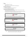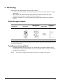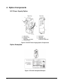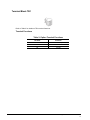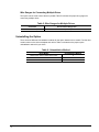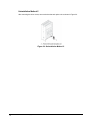
1
24 V Power Supply Installation Manual
PS-A10H and PS-A10L
November 2011
Part Number: 144-23928
© Copyright 2011 Magnetek
1. Preface and Safety
Magnetek manufactures products used as components in a wide variety of industrial systems and
equipment. The selection and application of Magnetek products remain the responsibility of the
equipment manufacturer or end user. Magnetek accepts no responsibility for the way its products are
incorporated into the final system design. Under no circumstances should any Magnetek product be
incorporated into any product or design as the exclusive or sole safety control. Without exception, all
controls should be designed to detect faults dynamically and fail safely under all circumstances. All
systems or equipment designed to incorporate a product manufactured by Magnetek must be
supplied to the end user with appropriate warnings and instructions as to the safe use and operation
of that part. Any warnings provided by Magnetek must be promptly provided to the end user.
Magnetek offers an express warranty only as to the quality of its products in conforming to standards
and specifications published in the Magnetek manual. NO OTHER WARRANTY, EXPRESS OR
IMPLIED, IS OFFERED. Magnetek assumes no liability for any personal injury, property damage,
losses, or claims arising from misapplication of its products.
Applicable Documentation
The following manuals are available for the option:
24 V Power Supply Option
IMPULSE®•G+/VG+ Series 4
Option 24 V Power Supply
Installation Manual
Manual No: 144-23928
Read this manual first.
The installation manual is
packaged with the option and
contains information required to
install the option and set up
related drive parameters.
MPULSE•G+/VG+ Series 4 Drive
The drive manuals cover basic
installation, wiring, operation
procedures, functions, troubleshooting,
and maintenance information. The
®•G+/VG+ Series 4 manuals also include important
IMPULSE
information about parameter settings
Instruction Manual
and drive tuning.
Access http://www.magnetekmh.com
to obtain Magnetek instruction
manuals.
IMPULSE®•G+/VG+ Series 4 24 V Power Supply Installation Manual - November 2011
1-2
Terms
Drive: IMPULSE®•G+/VG+ Series 4
Option: IMPULSE®•G+/VG+ Series 4 Option 24 VDC Power Supply
Registered Trademarks
Trademarks are the property of their respective owners.
Supplemental Safety Instructions
Read and understand this manual before installing, operating, or servicing this option. Install the
option according to this manual and local codes.
The following conventions indicate safety messages in this manual. Failure to heed these messages
could cause fatal injury or damage products and related equipment and systems.
DANGER
DANGER indicates an imminently hazardous situation which, if not avoided, will result in death
or serious injury. This signal word is to be limited to the most extreme situations.
WA R N I N G
WARNING indicates a potentially hazardous situation which, if not avoided, could result in
death or serious injury.
CAUTION
CAUTION indicates a potentially hazardous situation which, if not avoided, could result in
minor or moderate injury. It may also be used to alert against unsafe practices.
NOTICE
NOTICE indicates an equipment damage message.
NOTE:
A NOTE statement is used to notify installation, operation, programming, or
maintenance information that is important, but not hazard-related.
IMPULSE®•G+/VG+ Series 4 24 V Power Supply Installation Manual - November 2011
1-3
General Safety
General Precautions
•
•
•
•
The diagrams in this book may include options and drives without covers or safety shields to
illustrate details. Be sure to reinstall covers or shields before operating any devices. Use the
option according to the instructions described in this manual.
Any illustrations, photographs, or examples used in this manual are provided as examples only
and may not apply to all products to which this manual is applicable.
The products and specifications described in this manual or the content and presentation of the
manual may be changed without notice to improve the product and/or the manual.
When ordering new copies of the manual, contact a Magnetek representative and provide the
manual number shown on the front cover.
DANGER
Heed the safety messages in this manual.
Failure to comply may result in death or serious injury.
The operating company is responsible for any injuries or equipment damage resulting from
failure to heed the warnings in this manual.
NOTICE
Do not modify the drive or option circuitry.
Failure to comply could result in damage to the drive or option and will void warranty.
Magnetek is not responsible for any modification of the product made by the user. This product
must not be modified.
Do not expose the drive or option to halogen group disinfectants.
Failure to comply may cause damage to the electrical components in the drive or option.
Do not pack the drive in wooden materials that have been fumigated or sterilized.
Do not sterilize the entire package after the product is packed.
IMPULSE®•G+/VG+ Series 4 24 V Power Supply Installation Manual - November 2011
1-4
Option Label Warnings
Warning information is displayed on the option as shown in the Figure 1. Follow all warnings and
safety instructions when using the product.
When using the drive in an area that may require displaying warning information in Japanese and
English, a warning label is provided with the option. This label can be placed over the English and
French warnings on the front of the option.
Figure 1: Warning Labels
IMPULSE®•G+/VG+ Series 4 24 V Power Supply Installation Manual - November 2011
1-5
2. Product Overview
About This Product
The 24 V Power Supply option maintains drive control circuit power in the event of a main power
outage. As long as the control circuit has power, network communications and I/O data remain
operational. The option provides external power to the control circuit only, and does not provide
power to the main circuit of the drive.
It is possible to read fault and parameter data in the drive via the operator or network
communications when the drive switches to the option as a back-up power supply.
NOTE:
Parameter settings cannot be changed without drive main circuit power regardless of
whether the control circuit has enough power to operate.
Applicable Models
The 24 V Power Supply Option can be used with the drive models in Table 1.
Table 1: Applicable Models
Drive Series
G+/VG+ Series 4
Drive Voltage Class
Option Model
230 V Class
PS-A10L
460 V Class
575 V Class
IMPULSE®•G+/VG+ Series 4 24 V Power Supply Installation Manual - November 2011
1-6
PS-A10H
3. Receiving
Please perform the following tasks upon receiving the option:
• Inspect the option for damage. Contact the shipper immediately if the option appears damaged
upon receipt.
• Verify receipt of the correct model by checking the model number printed on the option
nameplate (refer to Figure 3 on page 1-8 for more information).
• Contact your supplier if you have received the wrong model or the option does not function
properly.
Option Package Contents
Description:
Option Unit
Warning Label
<1>
Screws (M3)
Installation
Manual
1
1
3
1
--
Quantity
<1> The warning label packaged with the option must be affixed to the option to maintain UL listing. Refer to Option Label Warnings on page 15 for instructions on label placement.
Tools Required for Installation
•
•
A Phillips screwdriver (M3 metric / #1, #2 U.S. standard size) is required to install the option.
A straight-edge screwdriver (blade depth: 0.015” [0.4 mm], width: 0.098” [2.5 mm]) is required to
wire the option terminal block.
NOTE:
Tools required to prepare option cables for wiring are not listed in this manual.
IMPULSE®•G+/VG+ Series 4 24 V Power Supply Installation Manual - November 2011
1-7
4. Option Components
24 V Power Supply Option
Figure 2: 24 VDC Power Supply Option Components
Option Nameplate
Figure 3: PS-A10L Nameplate Example
IMPULSE®•G+/VG+ Series 4 24 V Power Supply Installation Manual - November 2011
1-8
Terminal Block TB1
Refer to Table 2 for details on TB1 terminal functions.
Terminal Functions
Table 2: Option Terminal Functions
Terminal
Function
24
+24 VDC Input
0
0V
FE
Ground
IMPULSE®•G+/VG+ Series 4 24 V Power Supply Installation Manual - November 2011
1-9
5. Installation and Uninstallation Procedure
Section Safety
DANGER
Electric Shock Hazard
Do not connect or disconnect wiring while the power is on.
Failure to comply will result in death or serious injury.
Disconnect all power to the drive and wait at least the amount of time specified on the drive
front cover safety label. After all indicators are off, measure the DC bus voltage to confirm safe
level, and check for unsafe voltages before servicing. The internal capacitor remains charged
after the power supply is turned off.
WA R N I N G
Electrical Shock Hazard
Do not remove the front cover of the drive while the power is on.
Failure to comply could result in death or serious injury.
The diagrams in this section may include options and drives without covers or safety shields to
show details. Be sure to reinstall covers or shields before operating any devices. Use the
option according to the instructions described in this manual.
Do not allow unqualified personnel to use equipment.
Failure to comply could result in death or serious injury.
Maintenance, inspection, and replacement of parts must be performed only by authorized
personnel familiar with installation, adjustment, and maintenance of this product.
Do not touch circuit boards while the power to the drive is on.
Failure to comply could result in death or serious injury.
Do not use damaged wires, place excessive stress on wiring, or damage the wire insulation.
Failure to comply could result in death or serious injury.
Fire Hazard
Tighten all terminal screws to the specified tightening torque.
Loose electrical connections could result in death or serious injury by fire due to overheating of
electrical connections.
IMPULSE®•G+/VG+ Series 4 24 V Power Supply Installation Manual - November 2011
1-10
NOTICE
Damage to Equipment
Observe proper electrostatic discharge (ESD) procedures when handling the option, drive,
and circuit boards.
Failure to comply may result in ESD damage to circuitry.
Never shut the power off while the drive is running or outputting voltage.
Failure to comply may cause the application to operate incorrectly or damage the drive.
Do not operate damaged equipment.
Failure to comply may cause further damage to the equipment.
Do not connect or operate any equipment with visible damage or missing parts.
Do not use unshielded cable for control wiring.
Failure to comply may cause electrical interference resulting in poor system performance.
Use shielded twisted-pair wires and ground the shield to the ground terminal of the drive.
Properly connect all pins and connectors.
Failure to comply may prevent proper operation and possibly damage equipment.
Check wiring to ensure that all connections are correct after installing the option and
connecting any other devices.
Failure to comply may result in damage to the option.
IMPULSE®•G+/VG+ Series 4 24 V Power Supply Installation Manual - November 2011
1-11
Prior to Installing the Option
Prior to installing the option, wire the drive, make the necessary connections to the drive terminals,
and verify that the drive functions normally. Refer to the IMPULSE®•G+ & VG+ Series 4 Instruction
Manual packaged with the drive for information on wiring and connecting the drive.
Single Drive Installation
Figure 4 shows the installation distance required to maintain sufficient space for airflow and wiring.
Figure 4: Correct Installation Spacing
NOTE:
IP20/NEMA Type 1 Enclosure and IP00/Open-Chassis models require the same amount
of space above and below the drive for installation.
Dimensions
The option is 163 mm (6.4 in.) tall and adds 50 mm (2.0 in.) to the width of the drive when installed.
Figure 5: Dimensions
IMPULSE®•G+/VG+ Series 4 24 V Power Supply Installation Manual - November 2011
1-12
UL and CE Compliance
Installation Area
For compliance with UL and CE standards, the 24 V Power Supply Option should be placed within
the enclosure.
This product must be used in areas with an environment rating no greater than pollution degree 2
according to UL standards.
NOTE:
575 V class drives (models 5XXX-G+/VG+S4) are not compliant with European
Standards.
External Power Supply
Use a Class 2 power supply as defined by UL standards for the customer-supplied power supply
connection to TB1.
IMPULSE®•G+/VG+ Series 4 24 V Power Supply Installation Manual - November 2011
1-13
Option Installation Methods
There are three different installation methods for the option based on drive model. Find the drive
model number on the drive nameplate and refer to Table 3 to determine the proper option installation
method for your drive.
Table 3: Model-Specific Installation Methods
Drive Model (-G/VG+S4)
Installation Method
Page
2003 to 2075, 4001 to 4039, 5001 to 5027
A
1-14
2085 to 2415, 4045 to 4370, 5032 to 5200
B
1-18
4450 to 4605
C
1-22
Installation Method A
DANGER
Electric Shock Hazard
Disconnect all power to the drive and wait at least the amount of time specified on the drive
front cover safety label. After all indicators are off, measure the DC bus voltage to confirm safe
level, and check for unsafe voltages before servicing. The internal capacitor remains charged
after the power supply is turned off.
NOTICE
Damage to Equipment
Observe proper electrostatic discharge procedures (ESD) when handling the option, drive,
and circuit boards. Failure to comply may result in ESD damage to circuitry.
IMPULSE®•G+/VG+ Series 4 24 V Power Supply Installation Manual - November 2011
1-14
1. Shut off power to the drive, wait the appropriate amount of time for voltage to dissipate, then
remove the connector cover by pushing on the connector tab and sliding the cover towards the top of
the drive as indicated by the arrow in Figure 6.
Figure 6: Remove the Connector Cover
2. Pull the loose end of the connection cable out of the option.
Figure 7: Pull Out the Connection Cable
IMPULSE®•G+/VG+ Series 4 24 V Power Supply Installation Manual - November 2011
1-15
3. Firmly plug the end of the connection cable into the CN19 connection port on the drive.
NOTICE
Make sure the connector is facing in the proper direction when plugging it into the drive. An
improper connection can damage the connector and the drive.
Figure 8: Plug the Connection Cable into the Drive
4. Align the connector tabs on the option with the insertion tabs on the drive as shown in Figure 9.
Figure 9: Align the Option and the Drive
NOTE:
Take proper precautions when connecting the option so the option will easily fit onto the
drive. Make sure the connector cable is not pinched between the option and the drive.
IMPULSE®•G+/VG+ Series 4 24 V Power Supply Installation Manual - November 2011
1-16
5. Slide the option downward as indicated in Figure 10 to lock it into place on the drive.
Figure 10: Slide the Option onto the Drive
6. Skip to Option Wiring on page 28.
IMPULSE®•G+/VG+ Series 4 24 V Power Supply Installation Manual - November 2011
1-17
Installation Method B
DANGER
Electric Shock Hazard
Disconnect all power to the drive and wait at least the amount of time specified on the drive
front cover safety label. After all indicators are off, measure the DC bus voltage to confirm safe
level, and check for unsafe voltages before servicing. The internal capacitor remains charged
after the power supply is turned off.
NOTICE
Damage to Equipment
Observe proper electrostatic discharge procedures (ESD) when handling the option, drive,
and circuit boards. Failure to comply may result in ESD damage to circuitry.
1. Shut off power to the drive, wait the appropriate amount of time for voltage to dissipate, then use a
Phillips screwdriver (M4) to remove the screw holding the connector cover in place.
Figure 11: Remove the Connector Cover Screw
2. Slide the connector cover as shown in Figure 12.
Figure 12: Slide the Connector Cover
IMPULSE®•G+/VG+ Series 4 24 V Power Supply Installation Manual - November 2011
1-18
3. Insert the blade of a straight-edge screwdriver into the opening shown in Figure 13. Pull the
connector cover in the direction indicated by the arrow and remove it from the drive.
Figure 13: Remove the Connector Cover
4. Pull the loose end of the connection cable out of the option.
Figure 14: Pull Out the Connection Cable
IMPULSE®•G+/VG+ Series 4 24 V Power Supply Installation Manual - November 2011
1-19
5. Firmly plug the end of the connection cable into the CN19 connection port on the drive.
NOTICE
Make sure the connector is facing in the proper direction when plugging it into the drive. An
improper connection can damage the connector and the drive.
Figure 15: Plug in the Connector (2085-G+/VG+S4)
6. Align the connector tabs on the option with the insertion tabs on the drive as shown in Figure 16.
NOTE:
Take proper precautions when connecting the option so the option will easily fit onto the
drive. Make sure the connector cable is not pinched between the option and the drive.
Figure 16: Tab Locations
IMPULSE®•G+/VG+ Series 4 24 V Power Supply Installation Manual - November 2011
1-20
7. Use a Phillips screwdriver (M4) and the screws included in the option package to fasten the option
to the drive in the three locations shown in Figure 17.
NOTICE
Use only the screws packaged with the option; other screws may damage drive components.
Figure 17: Location of Screws
Figure 18: Option Properly Installed
8. Skip to Option Wiring on page 28.
IMPULSE®•G+/VG+ Series 4 24 V Power Supply Installation Manual - November 2011
1-21
Installation Method C
DANGER
Electric Shock Hazard
Disconnect all power to the drive and wait at least the amount of time specified on the drive
front cover safety label. After all indicators are off, measure the DC bus voltage to confirm safe
level, and check for unsafe voltages before servicing. The internal capacitor remains charged
after the power supply is turned off.
NOTICE
Damage to Equipment
Observe proper electrostatic discharge procedures (ESD) when handling the option, drive,
and circuit boards. Failure to comply may result in ESD damage to circuitry.
1. Shut off power to the drive, wait the appropriate amount of time for voltage to dissipate, then use a
Phillips screwdriver (M4) to remove the drive covers.
Figure 19: Remove the Covers
IMPULSE®•G+/VG+ Series 4 24 V Power Supply Installation Manual - November 2011
1-22
2. Remove the bracket used to hold the 24 V power supply unit in place.
Figure 20: Removing the bracket (4450-G+/VG+S4, 4605-G+/VG+S4)
Figure 21: Removing the bracket (4810-G+/VG+S4, 41090-G+/VG+S4)
3. Pull the loose end of the connection cable out of the option.
Figure 22: Pull Out the Connection Cable
IMPULSE®•G+/VG+ Series 4 24 V Power Supply Installation Manual - November 2011
1-23
4. As shown in Figure 23, the cable and connector should pass through the bracket.
Figure 23: Pass the cable and connector through the bracket
5. Connect the option unit to the bracket so that the connector tabs on the unit catch and hold it in
place.
Figure 24: Connecting the Option Unit to the Bracket
IMPULSE®•G+/VG+ Series 4 24 V Power Supply Installation Manual - November 2011
1-24
6. Use a Phillips screwdriver (M4) and the screws included in the option package to fasten the option
to the bracket in the three locations shown in Figure 25.
NOTICE
Use only the screws packaged with the option; other screws may damage drive components.
Figure 25: Securing the Option Unit to the Bracket
7. Firmly plug the end of the connection cable into the CN19 connection port on the drive.
NOTICE
Make sure the connector is facing in the proper direction when plugging it into the drive. An
improper connection can damage the connector and the drive.
Figure 26: Plugging the connector
IMPULSE®•G+/VG+ Series 4 24 V Power Supply Installation Manual - November 2011
1-25
8. With the option unit now affixed to the bracket, reinstall the bracket back in its original location.
NOTE:
Take proper precautions when connecting the option so the option will easily fit onto the
drive. Make sure the connector cable is not pinched between the option and the drive.
Figure 27: Installing the option unit
Figure 28: Option Properly Installed
IMPULSE®•G+/VG+ Series 4 24 V Power Supply Installation Manual - November 2011
1-26
9. Skip to Option Wiring on page 28. After wiring the terminal TB1, reinstall the drive covers to their
original locations.
Figure 29: Reinstall the covers to the drive
IMPULSE®•G+/VG+ Series 4 24 V Power Supply Installation Manual - November 2011
1-27
Option Wiring
1. Select an external power supply.
When the option is first switched on, two times the normal current will flow through the option for
approximately 0.5 seconds. The option requires at least 3 A to function properly.
WA R N I N G
Electric Shock Hazard
Use a battery or a double-reinforced UL Class 2 power supply to provide power to the option.
Using a different type of power supply may result in death or serious injury by electrical shock
or fire.
2. Wire the Terminal Block TB1.
Wire the external power supply to terminal block TB1 on the option.
Use a flat-blade screwdriver to loosen the screws on the 24 V power supply plug, connect wiring to
the 24 V, 0, and FE terminals as shown in Figure 30, then tighten the terminal screws to hold wiring
in place.
Refer to Wire Gauges and Tightening Torques on page 29 to confirm that the proper tightening
torque is applied to each terminal. Take particular precaution to ensure that each wire is properly
connected.
NOTICE
Be sure to properly connect an external 24 VDC power source to the power supply plug. Refer
to Option Specifications on page 34 for details. Improper wiring practices could damage the
option due to incorrect terminal connections.
Figure 30: Wire the 24 V Power Supply Plug
IMPULSE®•G+/VG+ Series 4 24 V Power Supply Installation Manual - November 2011
1-28
WA R N I N G
Fire Hazard
Tighten terminal screws to the specified tightening torque. Loose electrical connections could
result in death or serious injury by fire due to overheating. Tightening screws beyond the
specified tightening torque may cause erroneous operation, damage the terminal block, or
cause a fire.
NOTICE
Heat shrink tubing or electrical tape may be required to ensure that cable shielding does not
contact other wiring. Insufficient insulation may cause a short circuit and damage the option or
drive.
Connection Diagram
Figure 31 illustrates the 24 VDC Power Supply Option and drive connections.
Figure 31: Connection Diagram for Drive and Option
NOTE:
24 VDC external power supply input is supplied by the customer.
Wire Gauges and Tightening Torques
Table 4: Wire Gauges and Tightening Torques
Terminal
Number
24, 0, FE
Screw
Size
M2
Tightening
Torque
N-m (in-lb)
0.22 to 0.2
(1.95 to 2.21)
Bare Cable
Crimp Terminals
Applicable
Gauges mm2
Recomm.
Gauges mm2
Applicable
Gauges mm2
Recomm.
Gauges mm2
Wire
Type
Standard wire:
0.25 to 1.0
(24 to 17 AWG)
Single line:
0.25 to 1.5
(24 to 16 AWG)
0.75
(18 AWG)
0.25 to 0.5
(24 to 20 AWG)
0.5
(20 AWG)
Shielded
cable, etc.
IMPULSE®•G+/VG+ Series 4 24 V Power Supply Installation Manual - November 2011
1-29
Wire Gauges for Connecting Multiple Drives
The option can be wired to three drives in parallel. Table 5 indicates the proper wire gauges for
connecting multiple drives.
Table 5: Wire Gauges for Multiple Drives
Connectio
Recommended Gauges mm2
2 to 3 drives wired in parallel
0.5 (20 AWG)
Uninstalling the Option
There are three different Uninstallation methods for the option based on drive model. Find the drive
model number on the drive nameplate and refer to Table 6 to determine the proper option
uninstallation method for your drive.
Table 6: Uninstallation Method
Drive Model
Uninstallation Method
2003 to 2075, 4001 to 4039, 5001 to 5027
A
2085 to 2415, 4045 to 4370, 5032 to 5200
B
4450 to 4605
C
IMPULSE®•G+/VG+ Series 4 24 V Power Supply Installation Manual - November 2011
1-30
Uninstallation Method A
Insert the blade of a straight-edge screwdriver as shown in Figure 32, and gently slide the option in
the direction indicated by the arrow.
NOTICE
Do not use excessive force when uninstalling the option. Failure to comply can damage the
cable and connector.
Figure 32: Uninstallation Method A
Uninstallation Method B
Remove the three screws used to fasten the option into place during installation as shown in Figure
33 to uninstall the option.
Figure 33: Uninstallation Method B
IMPULSE®•G+/VG+ Series 4 24 V Power Supply Installation Manual - November 2011
1-31
Uninstallation Method C
After removing the drive covers, remove the bracket and option unit as shown in Figure 34.
Figure 34: Uninstallation Method C
IMPULSE®•G+/VG+ Series 4 24 V Power Supply Installation Manual - November 2011
1-32
6. Verifying Operation
After properly wiring and installing the option, use the following procedure to check for normal
operation:
1. Make sure the drive main circuit power is on, 24 VDC external power is supplied to the 24 V
connector plug, and the 24 V connector plug is connected to the option.
2. Switch off the main power supply to the drive. The 24 VDC external power supply should provide
power to the drive control unit.
3. Check for the red LED on the option indicating proper option operation.
4. The digital operator on the drive will display “Uv” for about 10 seconds to indicate an
undervoltage condition on the drive. If “Uv” does not flash on the display screen, check the
wiring. If “Uv” fails to appear on the digital operator after confirming proper wiring, the drive or
option may be damaged.
Power Supply and the Control Circuit
Table 7 outlines the various conditions under which the option provides power to the control circuit.
Table 7: Power Supply and Control Circuit
Drive Main Circuit Input Power from 24 V Power
Power Supply
Supply Option
ON
ON
ON
OFF
OFF
ON
OFF
OFF
Control Circuit
Operation in Drive
Drive Operation
Possible
Normal Operation
Possible
Not Possible
Stop
Not Possible
IMPULSE®•G+/VG+ Series 4 24 V Power Supply Installation Manual - November 2011
1-33
7. Specifications
Table 8: Option Specifications
Items
Option Input Operating Voltage
Specifications
24 VDC ± 20% (19.2 to 28.8 V)
Option 24 VDC Input Current
1.9 A
Consumption Power
38 W
Output Voltage
PS-A10L: 140 V
PS-A10H: 280 V
Output Power
30 W
Output Ride-Thru time (when power is off)
Over 50 ms
Ambient Temperature
-10 °C to +60 °C (14 °F to 140 °F) <1>
Storage Temperature
-20 °C to +70 °C (-4 °F to 158 °F) allowed for shortterm transport of the product
Maximum Possible Drive Connections
3
Weight
0.2 kg (0.4 lbs.)
Compliance
UL <2>, CE
<1> The option must be installed in an environment compatible with the drive environmental specifications.
<2> Use a Class 2, 24 VDC UL power supply to meet UL requirements.
IMPULSE®•G+/VG+ Series 4 24 V Power Supply Installation Manual - November 2011
1-34