1
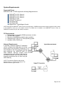
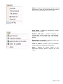
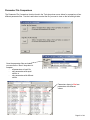
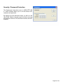
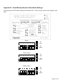
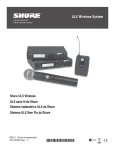
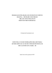
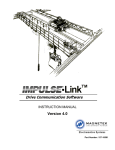
Magnetek Material Handling IMPULSE®•LINK 4.1 WDS Wireless Diagnostic System Instruction Manual October 2011 Part Number: 140-10330-R6 ©Copyright 2011 Magnetek Material Handling ©2011 MAGNETEK MATERIAL HANDLING All rights reserved. This notice applies to all copyrighted materials included with this product, including, but not limited to, this manual and software embodied within the product. This manual is intended for the sole use of the persons to whom it is provided, and any unauthorized distribution of the manual or dispersal of its contents is strictly forbidden. This manual may not be reproduced in whole or in part by any means, whatsoever, without the expressed written permission of MAGNETEK. IMPULSE•LINK 4.1 Software is copyrighted by Magnetek. All rights reserved. Page 1 of 44 Table of Contents Chapter 1 - Introduction ................................................................................................................ 4 Overview .................................................................................................................................................................. 4 System Requirements ............................................................................................................................................. 6 Chapter 2 - Installation ................................................................................................................. 7 Software Installation ................................................................................................................................................ 7 Installing your Hardware Key .................................................................................................................................. 8 Importing your Drive Profiles ................................................................................................................................... 9 Creating Communication Profiles using the Wizard .............................................................................................. 10 Hardware Installation ............................................................................................................................................. 11 Wiring the Base Unit .............................................................................................................................................. 11 Wiring the Remote Unit ......................................................................................................................................... 12 Chapter 3 - Navigation ............................................................................................................... 14 Chapter 4 - Parameter Maintenance .......................................................................................... 18 Read From VFD .................................................................................................................................................... 18 Write to VFD .......................................................................................................................................................... 18 Parameter File Display .......................................................................................................................................... 19 Modifying Parameters............................................................................................................................................ 19 Parameter File Comparison................................................................................................................................... 21 Custom Defaults .................................................................................................................................................... 22 Security / Password Protection ............................................................................................................................. 23 Chapter 5 - Monitor / DataLogger Function ................................................................................ 24 Monitor ................................................................................................................................................................... 24 DataLogger ............................................................................................................................................................ 24 Fault Reset ............................................................................................................................................................ 28 Chapter 6 - Additional Menu Features ........................................................................................ 30 Print Preview ......................................................................................................................................................... 30 Parameter File Conversion .................................................................................................................................... 31 Viewing Parameters .............................................................................................................................................. 32 Copying to the Clipboard ....................................................................................................................................... 32 Chapter 7 - Troubleshooting ....................................................................................................... 33 Drive Faults References ........................................................................................................................................ 33 Communication Error References ......................................................................................................................... 34 Communication Profile Test .................................................................................................................................. 35 Show Error Log ...................................................................................................................................................... 35 Chapter 8 - Appendices .............................................................................................................. 36 Appendix A: Appendix B: Appendix C: Appendix D: Appendix E: Appendix F: Serial Wiring for IMPULSE®•LINK WDS Base Unit ......................................................................... 36 Serial Wiring for IMPULSE®•LINK WDS Remote Unit ..................................................................... 37 Serial Wiring for IMPULSE®•G+/VG+ Series 2 ................................................................................ 40 Serial Modem (Remote Unit) Switch Settings ................................................................................. 41 Termination Resistor Location ......................................................................................................... 42 Quick Reference .............................................................................................................................. 44 Page 2 of 44 Warning and Caution DISCLAIMER OF WARRANTY Magnetek’s Electromotive Systems, hereafter referred to as Company, assumes no responsibility for improper programming of a drive that resulted from use of this software. This software should only be used by a trained technician who has read and understands the contents of this manual. Normal use of this software may result in the drive parameters becoming modified. Improper programming of a drive can lead to unexpected, undesirable, or unsafe operation or performance of the drive. This may result in damage to equipment or personal injury. Company shall not be liable for economic loss, property damage, or other consequential damages or physical injury sustained by the purchaser or by any third party as a result of the use of this software. Company neither assumes nor authorizes any other person to assume for Company any other liability in connection with the sale or use of this software. 1. Read this user manual in its entirety before installing IMPULSE®•LINK 4.1 Wireless Diagnostic System (WDS) or operating the IMPULSE®•G+/VG+ Series 4, IMPULSE®•G+/VG+ Series 3, IMPULSE®•G+/VG+ Series 2, IMPULSE®•G+ Mini, IMPULSE®•P3 Series 2, OmniPulse DDC Variable Frequency Drives (VFD), OmniPulse DSD DC Drive, and/or the MagnePulse™ Digital Magnet Control. 2. DO NOT connect or disconnect wiring, or perform signal checks while the electrical power is turned ON. 3. Improper programming of a drive through the use of this software can lead to unexpected, undesirable, or unsafe operation or performance of the drive. Failure to observe these and other precautions indicated in this manual will expose the user to high voltages, resulting in serious injury or death. Damage to equipment may also occur. NOTICE No patent liability is assumed with respect to the use of the information contained herein. Moreover, Magnetek is constantly improving its high quality product; therefore, the information contained in this manual is subject to change without notice. Every precaution has been taken in the preparation of this document. Nevertheless, Magnetek assumes no responsibility for errors or omissions. Neither is any liability assumed for damages resulting from the use of the information contained in this publication. Page 3 of 44 Chapter 1 - Introduction Overview IMPULSE®•LINK 4.1 Wireless Diagnostic System (WDS) is a user friendly, Windows® based, interactive drive communication software and wireless hardware package. It is designed for communication from your PC over your company-wide network to the following Magnetek drives: IMPULSE®•G+/VG+ Series 4 IMPULSE®•G+/VG+ Series 3 IMPULSE®•G+/VG+ Series 2 IMPULSE®•G+ Mini IMPULSE®•P3 Series 2 OmniPulse DDC OmniPulse DSD MagnePulse™ Digital Magnet Control (DMC) IMPULSE®•LINK 4.1 WDS consists of: 1. A base unit consisting of a wireless modem connected to a PC using company-wide network. 2. A remote unit consisting of a wireless modem, which is wired to your IMPULSE® Drives and communicates wirelessly to the base unit. 3. IMPULSE®•LINK 4.1 WDS Software that allows access to all of the cranes in your facility from one location. A hardware key must be present in the computer’s USB port to enable the software to access the drives. The Wireless Base Unit Model number: WDS-EBASE Description: NEMA 4 junction box (12″ x 10″) consists of a 120-volt GF1 power outlet, Ethernet wireless modem, externally mounted antenna to the junction box, Ethernet receptacle built-in to the junction box, and terminal block. Along with the NEMA 4 junction box is a 6′ crossover cable with Ethernet receptacle. The Wireless Remote Unit Model number: WDS-SREMOTE Description: NEMA 4 junction box (12″ x 10″) consists of a 120-volt GF1 power outlet, wireless modem, externally mounted antenna to the junction box, and terminal block. Along with the NEMA 4 junction box, the remote unit comes with 50′ of Belden twisted shielded cable to connect the drives to the modem. Software and Hardware Key Model number: WDS-SWARE Description: CD containing the IMPULSE®•LINK 4.1 WDS software, customer’s drive profiles, and the hardware key. Remote Antenna Kit Model number: WDS-ANTENNAKIT Description: Hardware and accessories to remotely mount the WDS antenna (up to 10 feet from WDS Wireless Remote Unit). Page 4 of 44 IMPULSE® Link•4.1 Wireless Diagnostic Ethernet Remote Unit Model number: IL-WDS-REMOTE-DC Description: 90-350VDC Supply, NEMA 4 enclosure (with wireless modem, antenna, and power supply) and 50 feet of serial cable (one remote unit required per crane). Din Rail Power Supply Model number: IL-WDS-PS Description: Din Rail Power Supply for RS-232 to RS-485 Converter Power supply for the RS-232 to RS-485 Converter. SPECIFICATIONS Wireless Base Unit Enclosure: Dimension (H x W x D): Temperature: Humidity: Voltage: Wattage: Communication: Frequency: NEMA 4 12 x 10 x 5 inches (30.5 x 25.4 x 12.7 cm) 32 – 104 °F (0 to 40 °C) 0-95% Non-condensing 120 VAC single phase, 0.8 Amps 1 Watt Ethernet TCP/IP 10/100 Base-T 900 MHz, Frequency Hopping, Spread spectrum Wireless Remote Unit Environment: Dimension (H x W x D): Temperature: Humidity: Voltage: Wattage: Communication: Frequency: Range: Serial Cable: NEMA 4 12 x 10 x 5 inches (30.5 x 25.4 x 12.7 cm) 32 – 104 °F (0 to 40 °C) 0-95% Non-condensing 120 VAC single phase, 0.8 Amps 1 Watt RS485 4-wire, 120 Nominal Characteristic Impedance (Belden 9842) 900 MHz, Frequency Hopping, Spread spectrum 100 feet (30.48 meters) line-of-sight, 300 feet (91.4 meters) typical from base unit Belden 9842 2 twisted pair shielded cable, 120Ω impedance Page 5 of 44 System Requirements Supported Drives IMPULSE®•LINK 4.1 WDS supports the following Magnetek drives: IMPULSE®•G+/VG+ Series 4 IMPULSE®•G+/VG+ Series 3 IMPULSE®•G+/VG+ Series 2 IMPULSE®•G+ Mini IMPULSE®•P3 Series 2 OmniPulse DDC OmniPulse DSD MagnePulse™ Digital Magnet Control NOTE: Although the IMPULSE® Series 2 drives are supported, a CMG5M communication board (part #140-10261) needs to be installed on each G+ or VG+ Series 2 drive. If a G5IN4 card is installed on an IMPULSE® Series 2 drive, an RS485/232 converter kit (P/N 144-12545) is required. PC Requirements 1. 2. 3. 4. 5. Pentium class or equivalent 500MHz processor or better 256 MB RAM or greater Minimum of 100 MB free hard-disk space available Windows 98 SE, 2000, XP or Vista operating system. Available USB or RS232 port. Network Requirements If specified, customer-supplied IP addresses can be configured into each base unit during factory setup. A tool, the WDS Configurator, is also included on the CD to assist in scanning and configuring the IMPULSE®•LINK 4.1 WDS Modems. Although multiple users (computers) may have access to the drives on an Ethernet network, only one person can be accessing a particular bay at a time using the WDS Wibu key. NOTE: The maximum Ethernet cable length between devices is 328 feet (100 meters). The Ethernet connector type is RJ-45. Page 6 of 44 Chapter 2 - Installation Software Installation The IMPULSE®•LINK 4.1 WDS CD contains: the IMPULSE®•LINK 4.1 WDS Software and the communication profiles for the IMPULSE Drives used in your specific application. To run the IMPULSE®•LINK 4.1 WDS Setup, put the IMPULSE®•LINK 4.1 WDS CD into your CD drive (run setup.exe from the CD if it does not start automatically). Select the default choices during installation. Page 7 of 44 Installing your Hardware Key Insert your WDS Wibu hardware key into any USB port on your computer. Windows will detect the hardware and begin installing the necessary drivers. Select Next, leaving the (Recommended) choice selected. Wait while the hardware is installed. Windows will find the correct driver and install it. Click Finish to close the Completing the Found New Hardware Wizard dialog. NOTE: If you try to run IMPULSE®•LINK 4.1 WDS and the hardware key is not inserted into a USB port on the computer, you will receive the following error message. Also, if you are running IMPULSE®•LINK 4.1 WDS and remove the hardware key, the same message will appear until the key is re-inserted into the USB port. Software Updates Additional features and software enhancements may be available from time to time. These may be downloaded from the Magnetek Material Handling website at www.magnetekmh.com/downloads.htm. Software Removal To remove the IMPULSE®•LINK 4.1 WDS Drive Interface Software, open the Control Panel’s Add/Remove Programs dialog box, double-click the IMPULSE®•LINK 4.1 WDS entry and choose Remove All from the IMPULSE®•LINK 4.1 WDS Setup dialog box. Page 8 of 44 Importing your Drive Profiles If you request your crane profile and Ethernet IP address to be configured at the factor, your profile will reside on the installation CD. When IMPULSE®•LINK 4.1 WDS is installed, the profiles will be imported automatically for you. Run IMPULSE®•LINK 4.1 WDS by double-clicking the “L” icon found on your desktop. A splash screen will appear for a few seconds while the subsystem loads. To import the profiles manually: 1. Select “Communication” from the Settings Menu. 2. Right-Click on the “Communication Profiles“ Folder and select “Import From File” 3. Browse to your CD-ROM drive, select the files (*.CPX) and choose “Open”. 4. There will be a profile for each drive (Crane 1 Hoist, Crane 1 Bridge, etc.) 5. After the profiles are imported, select “OK” to save your communication profiles. Page 9 of 44 Creating Communication Profiles using the Wizard If you need to create a communication profile, there is a wizard to assist you. In the Settings Menu, click “Communication,” and then right-click on the folder “Communications Profile” and choose “Add Crane Folder”. Enter the name of your crane for the folder. Rightclick on this new folder and choose “Add Profile”. You will then see the following screen appear: Highlight the IMPULSE DRIVE, WM-E for the WDS Wireless Ethernet Modem, and then click “Select”. The wizard will then take you through the following four steps to set up a new communication profile. Step 1: Step 2: Step 3: Step 4: Step 5: Step 6: Name, Description, Crane and Motion IP Address for the Base Unit Slave Address (01H to 1FH) and Parity (0:None) Finish Click OK To save, click OK on the Communication Profile screen NOTE: Profiles created will not be saved if Cancel is used Page 10 of 44 Hardware Installation Mounting Be sure that the base and remote units are mounted in a location protected against the following conditions: Extreme cold or heat. Use within the ambient temperature range of: o Base Unit 32° to 104°F (0° to 40°C) o Remote Unit 32° to 104°F (0° to 40°C) Direct sunlight Direct rain, moisture High humidity o 0 to 95% Non-condensing Oil sprays, splashes Salt spray Corrosive gases The base and remote units should be mounted on a flat, non-flammable vertical surface using four mounting screws. Line of sight should be maintained from both the remote unit’s and base unit’s antennas to avoid communication dropouts. Wiring the Base Unit The Base Unit contains an Ethernet wireless modem. The Base Unit has an Ethernet receptacle at the bottom of the enclosure. A 6′ cross-over cable with Ethernet connector is provided with the Base Unit. This 6′ crossover cable can simply be plugged into the Ethernet port on a computer and then the opposite end can be plugged into the Base Unit’s Ethernet receptacle. The Ethernet field connector kit (shown below) provides strain relief and can be cut-off from the 6′ cross-over cable and connected to an alternative cable of desired length when connecting to an Ethernet switch or hub. At the bottom right of the Base Unit enclosure is a cable grip for running the 115V control power wiring. The Ethernet receptacle is built in to the bottom left of the enclosure. Ethernet and control power wiring should never be run together. The typical wiring diagram for the Base Unit can be found in Appendix A. Page 11 of 44 Wiring the Remote Unit The Remote Unit contains two cable grips on the bottom of the enclosure. It is important that control and serial wiring are run separately. The Remote Unit comes with 50 feet of twisted shielded cable (Belden 9842) for wiring to your drives. IMPULSE®•G+/VG+ Series 2 drive: The IMPULSE®•G+ and VG+ Series 2 require a CMG5M serial option board. Connect multiple IMPULSE®•G+/VG+ Series 2 drives, using terminals 1–4 on the CMG5M board as shown in Appendix C. OmniPulse DDC drive: The OmniPulse DDC supports the 2-wire RS485 interface only. If any other IMPULSE® Series AC drive is connected to the network, it must be wired as RS485 2-wire. Wiring to the Drives When wiring the IMPULSE®•P3 Series 2, IMPULSE®•G+/VG+ Series 3 or OmniPulse DDC drives, the serial communication terminals are located on the control interface board. See Appendix E for additional details. 1. Locate the correct terminals. 2. Use the twisted shielded wire provided with your Remote Unit for connecting as indicated in the table below. Wireless Remote Unit Terminal Block 8 or R+ 2 or R7 or S+ 3 or SShield 1 2 3 4 IMPULSE®•G+/VG+ Series 4 IMPULSE®•G+/VG+ Series 3 IMPULSE®•G+ Mini IMPULSE®•P3 Series 2 Control Terminals R+ RS+ S- T1-9 – RS485B (T/R+) T1-8 – RS485A (T/R-) N.C. N.C. TC2 TB4 Chassis Ground ® IMPULSE •G+/VG+ Series 2 CMG5M Board Terminals OmniPulse DDC MagnePulse DMC Description RS-485 signal RS-485 signal RS-485 signal RS-485 signal Shield connection 3. Set the terminating resistor. NOTE: Reference the drawings included in the WDS Remote unit or the wiring diagrams in the Appendix of this document for more information. Page 12 of 44 Terminating Resistor There is a dipswitch that is used to connect a terminating resistor (120 Ohms) to the serial communications for proper network balancing (see Appendix E for location). This terminating resistor needs to be ON at the beginning and end of the line for the RS485 communications. The Impulse Link Remote Unit has the terminating resistor enabled from the factory. Use a daisy-chain wiring configuration for connecting multiple drives. The terminating resistor should be turned ON, for one-to-one connections or on the last drive, when multiple drives are wired in parallel. Below is an overview of the daisy-chain configuration. One-to-one connection Multiple drive connection Page 13 of 44 Chapter 3 - Navigation The IMPULSE®•LINK 4.1 WDS Software is a Windows-based software with easy to use menus and drop-down functions. The user is able to access utilities for uploading/downloading parameters, comparing parameters, saving parameters to a file, accessing the DataLogger function and more from the easy to navigate toolbar. The main screen allows the user to access more commonly used features at click from the main screen. New – Displays the controller properties dialog to create a new factory default parameter set, based on the drive type, software number, model, and kVA. Open – Opens or finds a file containing a parameter set for a specific drive type and software number. Profile – Shows the selected profile. Save – Saves the active file with its current file name and location. Print – Prints the active parameter set. Select Print options, in the Print window/dialog box. Print Preview – Shows how a file will look when you print it. Show Error Log – shows the status of IMPULSE®•LINK 4.1 WDS. IMPULSE LINK Help – Provides information on communication profile settings and troubleshooting, complete Index of VFD fault codes, and a Search function. Write to VFD - Saves all parameter values from memory to the VFD. Read from VFD - Loads all parameter values from the VFD to memory. Properties – Displays the properties box to view the properties of the active file. Page 14 of 44 The following gives a brief summary each of the functions that can be accessed from the navigation toolbar. New – Displays the controller properties dialog to create a new factory default parameter set, based on the drive type, software number, model, and kVA. Open – Opens a *.par file containing a parameter set for a specific drive type and software number. Save – Saves the active file with its current file name and location. Save As – Saves the active file with a different file name or location. Print Preview – Shows how a file will look when you print it. Print – Prints the active parameter set. Select Print options, in the Print window/dialog box. Properties – Displays the properties box to view the properties of the active file. Exit – Closes this program after prompting you to save any unsaved files. Communication – Allows communication profiles to be added, removed, edited, copied, imported and exported. Preferences – IMPULSE®•LINK 4.1 WDS settings for access level. Custom Defaults – Contains screen for maintaining “custom default” parameter files. Page 15 of 44 Write Flash - Allows a binary file to be written to VFD flash memory. (FACTORY USE ONLY) Read from VFD - Loads all parameter values from the VFD to memory. Write to VFD - Saves all parameter values from memory to the VFD. Convert – Allows for parameter files to be converted from one software/Flash ID to another (must be within the same drive series). Compare Parameters - Allows for comparison between two different parameter files. Communication Test – performs a communication test with the VFD. Monitor – Displays a select number of monitor parameters (U-parameters), updated continuously. DataLogger – Opens the DataLogger function (described in more detail in Chapter 5). Keypad Simulator – Emulates the keypad and allows for navigating the keypad menu remotely (this is not available unless hardwired to the keypad port). Show Error Log – shows IMPULSE®•LINK 4.1 WDS. the status of Page 16 of 44 Window - Allows for easy parameter window recall and organization. All open files are enumerated at the bottom of this menu for switching between files more easily. Users Manual – Displays the User Manual. (Acrobat Reader must be installed) IMPULSE LINK Help – Provides information on communication profile settings and troubleshooting, complete Index of VFD fault codes, and a Search function. Electromotive on the Web – provides a link to the Magnetek Material Handling website. Check for Updates – provides a link to the download software page of the website that offers updates. About - Displays the version number of this Electromotive Systems product, copyright and legal notices. Page 17 of 44 Chapter 4 - Parameter Maintenance IMPULSE®•LINK 4.1 WDS software provides flexibility in programming, uploading, downloading, and saving parameters. With full parameter descriptions and visual programming, modifying parameters from your computer has never been easier. Read From VFD This function allows you to load the parameter values from the drive’s memory. This can be accomplished through the ‘VFD’ drop down menu or the ‘Read’ Icon (as shown below). Write to VFD This function saves all parameter values from memory to the VFD. This can be accomplished via the drop down on the ‘VFD’ menu or using the ‘Write’ Icon as shown here. Writing to the VFD may result in undesirable operation of your crane, causing danger, personal injury or death! To proceed with the write to VFD function you will need to accept that you acknowledge the warning message as shown here. Once you have checked the I Accept button, the Continue write to VFD button will be available. Page 18 of 44 Parameter File Display Parameter Value Text Color Modified Constant A parameter with blue text implies that its value is different than its default setting. - This list should match the modified constants list in the drive, with the exception of A1 parameters. Read-Only A grayed-out, highlighted parameter implies that it cannot be modified. - The Access Level of the current parameter set is lower than what is needed for this specific parameter (i.e. changing this parameter from the drive keypad would not be allowed with the current access level). Over Maximum A parameter with red text implies that its value is greater than its maximum. An invalid value in the PAR file could result in this error. Under Minimum A parameter with green text implies that its value is less than its minimum. An invalid value in the PAR file could result in this error. Modifying Parameters 1. Begin modifying a parameter by double-clicking on the row of the parameter. 2. A drop-down list or edit box will appear in the Setting column. 3. Press Enter to accept the change or Escape to cancel. Drop-down List Example. This is displayed for drive parameters with a finite list of options. Edit Box Example This is displayed for drive parameters with a numeric range. Notes: 1. If a change is made, ENTER is not pressed to accept it, and the user clicks on another row or column, the value will revert back to what it was before the change. 2. If a parameter is changed to an invalid value, under the minimum value or over the maximum value, an appropriate message will be displayed and the value being edited will revert back to what it was before the change. Page 19 of 44 Visual Programming Visual Programming is an additional editing option targeted towards more complicated parameters or parameters with extended settings that require using a table to calculate the value. Parameters with a Visual Programming option display an icon. To Edit: 1. Left-click once on the Visual Programming icon. 2. Click on the appropriate selections. 3. Choose OK to accept the change or Cancel to abort. Page 20 of 44 Parameter File Comparison The Parameter File Comparison function found in the Tools drop-down menu allows for comparison of two different parameter files. Use the Load button to select the file you want to view on the left and right side. Once the parameter files are loaded, you can use the “Show” drop-down to compare: all parameters of each file, only parameters with equal values, or only parameters with different values. Parameters shown in Red are parameters with different values. Page 21 of 44 Custom Defaults This function allows for the comparison of your current drive parameters to a custom default set versus factory default. This allows for a quick analysis of incorrect or non-uniform parameter settings within a file, without having to compare multiple files. Setting Up Your Custom Defaults: Custom Defaults are organized into Groups and Files. Each Group contains files with a unique combination of drive type, flash ID and model. Maintenance screens are provided for adding and removing these files. Alternatively, the user may also copy the entire “CustomDefaults” sub-directory from computer to computer. When IMPULSE®•LINK 4.1 first loads, it scans the “CustomDefaults” sub-directory for valid PAR files. NOTE: The default IMPULSE®•LINK 4.1 WDS path is “C:\Program Files\Electromotive Systems\Impulse Link 4.1\” Using Custom Defaults: Using Custom Defaults is not much different than viewing Modified Constants. If the selected PAR file matches the drive type, flash ID and model within one of the Groups, the Group will appear in the drop-down. When a Group is selected, an additional column is displayed and the parameter file is filtered by whether the value matches the custom default (rather than the factory default). Page 22 of 44 Security / Password Protection The ‘Preferences’ drop-down menu in IMPULSE®•LINK 4.1 WDS software allows you to set the access level, username and password. By logging out of the Advanced mode, you will be in the User mode. While in the User mode, the drives can only be monitored. Write to VFD and Reset functions are NOT available. Page 23 of 44 Chapter 5 - Monitor / DataLogger Function Monitor There is a ‘Monitor’ function in the ‘Tools’ drop–down, which displays a select number of monitor parameters (U-parameters) that are continually updated. DataLogger The DataLogger function provides monitoring of multiple IMPULSE® drives simultaneously while it also records run, fault and alarm events to file. NOTE: A displayed fault may be clicked on to bring up corresponding help content. A DataLogger file (DS3) contains a limited number of events. When the maximum has been reached, the oldest entry is replaced. For each event, there are corresponding voltages, currents and frequencies recorded at the time the event occurred. For faults and alarms, additional data that occurred just prior to the event is also logged. This is known as Trace data. Available Events: 1400 run events 200 alarm events 200 fault events. A DataLogger file may be e-mailed for additional troubleshooting assistance. NOTE: The DataLogger function does not support data logging of IMPULSE®•P3 Series 2 drives. Page 24 of 44 To Begin 1. Click the check box of the drive(s) you want to monitor. 2. Click the play button. The left window will change to show a button for each of the drives you selected and the overall status of the drive after it initializes connection. Each button will display a different color base on the status of the drive profile. White background with black text – normal operation of the drive. Yellow background with black text – there is an alarm present on the drive. Red background with white text – there is a fault present on the drive. Page 25 of 44 This button also contains a brief description of the status. The following table lists these brief text messages displayed along with a description for each. Brief Text Displayed Alarm Communication Error <error code> Connected! Connecting… Disconnected Drive Not Supported Faulted Forward Initializing… Reverse Stopped Zero Spd Description Drive has an Alarm IMPULSE®•LINK is having trouble communicating with the drive. An error code will be shown to further assist IMPULSE®•LINK has established connection to the drive IMPULSE®•LINK is preparing the communication with the drive Communication has been lost between IMPULSE®•LINK and the drive The drive selected is not supported by the DataLogger function Drive has a fault Drive is being issued “Forward” command to run. IMPULSE®•LINK is trying to establish communication with the drive Drive is being issued “Reverse” command to run. Drive is stopped Drive is at “Zero Speed” Clicking the button in the left window for the drive, the right window will show the profile of the drive selected at the top along with continually updated information. There are 4 main areas displayed. 1) Profile of the drive selected showing Profile - Displays the drive profile and 2) Summary other information about the drive 3) Monitor, and 4) Status Summary – Displays current status of drive including last fault or alarm Monitor – Displays selected monitor parameters (U-Parameters). Status – Shows the status of input and output terminals along with a visual of the drive status. Page 26 of 44 In the summary window if a Fault or Alarm condition occurs, the DataLogger allows you to click on the Alarm or Fault, and displays troubleshooting information (as shown here). The Status window allows for the viewing of input and output terminal status. By using your mouse, you can roll over the LED to view the meaning. See the example below. Terminal 5 is ON Page 27 of 44 Fault Reset In the event of a fault condition, you will see the fault icon on either the DataLogger window or the Monitor window as indicated below. Fault Reset Icon NOTE: You can reset a fault in the Monitor window or DataLogger window, as long as the drive doesn’t have a Run command and the fault condition no longer exists. Once you click on the fault reset icon (as shown above), a warning message will prompt you to accept that you acknowledge the warning. When resetting a drive remotely, you need to be sure that all personnel and/or operators are notified. Once you have checked the “I accept” box, the “Continue Fault Reset” button will be available. Page 28 of 44 Fault / Alarm / Run history Click on any one of the three icons (Fault/Alarm/Run) at the top of the DataLogger will change the view to show three new tabs. Each tab will allow you to view the Fault, Alarm, or Run History for the drive. In this window you can view the History for each tab. Clicking on the plus (+) sign will show additional information related to the fault or alarm. Page 29 of 44 Chapter 6 - Additional Menu Features Print Preview IMPULSE®•LINK 4.1 WDS provides a compact printing mode that displays all drive parameters in only 1-2 pages. It also prints a more detailed mode that lists descriptions as well as units for each parameter. Compact Parameter Print Preview Detailed Parameter Print Preview Print Printer Name – Allows the user to select from any printer installed on his/her system. The user’s default printer is initially selected. Print Mode - Allows the user to choose the printing style. o Compact mode (1-2 pages) provides parameter name and setting value. o Detailed mode provides parameters, descriptions, setting, values and units as well as ‘modified’ information. o As shown prints all of the information as shown on the screen. OK Button – Prints the active parameter set to the selected printer in the chosen format. Cancel – Closes this dialog box without printing. Changes to Customer Name, Application and Job Number are not saved. Text placed in the Customer Name, Application and Job Number fields appear on the printout. NOTE: Only parameters that are viewable in the Parameters Window will be printed. Page 30 of 44 Parameter File Conversion ‘Convert’ under the ‘Tools’ menu allows for parameter files to be converted from one software/Flash ID version to another (within the same drive series). Source – Specifies the file to be converted. Flash ID – Specifies the software type that the file will be converted to. Destination Filename – Specifies the Destination filename. Convert - Converts the parameter file specified in “Source” to the format specified in the software version in the Flash ID. The converted file is saved to the filename and path specified in “Destination Filename”. Keypad Emulator – The keypad emulator communicates with an IMPULSE® drive exactly as the physical keypad does. This allows for remote keypad menu navigation. NOTE: This function is only available when IMPULSE®•LINK 4.1 WDS is connected via the drive’s keypad 1CN connector (instead of the standard RS485 connection) – primarily for training purposes. If you attempt to run the keypad simulator while connected via the standard RS485 connection a CF00 Comm Error will occur. Digital Operator Emulator NOTES: 1. To Activate, Select the correct drive profile from the dropdown and click the button. 2. The Keypad will automatically close if any communication function, such as Upload and Download, or a new offline parameter set is created from the Controller Properties window. 3. The RUN command has been disabled for safety reasons. 4. If the drive is put into “Program Mode” and not returned to “Run Mode”, the user will be unable to run the drive. Page 31 of 44 Viewing Parameters The ‘View’ drop-down box allows filtering of parameters based on parameter group organization and the parameter value (modified from factory defaults or from custom defaults). Copying to the Clipboard IMPULSE®•LINK 4.1 provides the ability to copy displayed parameter information to a preferred word processor or spreadsheet. To do this, select one or more rows and either press Ctrl-C or right-click to display the context menu, shown to the right. The copied information is available to be pasted in either HTML format or ASCII text. Tip: Change from full row selection mode to single cell selection mode by doing the following. 1. Click and hold the left mouse button over any row. 2. Drag the mouse down while the left-mouse button is still being held. An icon will replace your mouse pointer. 3. While still holding the left mouse button, click the right mouse button. The icon will become skinnier and you will no longer be restricted to selecting the whole row. Repeat to return to full row mode. Page 32 of 44 Chapter 7 - Troubleshooting The IMPULSE®•LINK 4.1 WDS Help section provides the following: Reference to Drive faults and corrective actions. Reference to IMPULSE®•LINK error codes and corrective actions. Communication profile settings overview. Drive Faults References IMPULSE®•LINK 4.1 WDS offers built-in Help screens for the drive faults and/or alarms. The Help screens provide advanced diagnostics allowing you to troubleshoot your drive from your PC. When you ‘click’ on the fault, the help screen provides the fault code, fault name/description, and the corrective action. Or you can simply go to the Help Icon and go to the Drive Fault References for a complete list of G+ Mini, P3 Series 2, G+/VG+ Series 2, 3, and 4 drive faults, as shown below: Page 33 of 44 Communication Error References The Help function provides an overview of the possible errors that could occur while running IMPULSE®• LINK 4.1 WDS, as shown here: By clicking on the type of error, you will be provided the fault code with description and correction action. Page 34 of 44 Communication Profile Test The Communication Profile Test Utility is a tool to assist in troubleshooting communication difficulties. It performs the following sequence: 1. Opens the communication port with the selected settings. If the port opens successfully, the port exists and IMPULSE®•LINK has access to it. 2. Sends a loop-back test message to establish whether a valid device exists with the settings in the profile. If the loop-back fails, the device may not be powered, present or supported. 3. Identifies the drive model and version. If the discovered type is unknown, IMPULSE®•LINK does not support it. NOTE: If any of the above steps fail, an error message is prompted to the user with an error code (i.e. CE100). For further troubleshooting reference the error code in the help section. Show Error Log This function, also found in the Tools drop-down menu, brings up an additional window showing various status details of IMPULSE®•LINK 4.1 WDS. Page 35 of 44 Chapter 8 - Appendices Appendix A: Serial Wiring for IMPULSE®•LINK WDS Base Unit Page 36 of 44 Appendix B: Serial Wiring for IMPULSE®•LINK WDS Remote Unit (G+/VG+ Series 4, G+/VG+ Series 3, P3 Series 2, and G+ Mini) Page 37 of 44 Wiring for IMPULSE®•LINK WDS Remote Unit (OmniPulse DDC and MagnePulse DMC) Page 38 of 44 Wiring for IMPULSE®•LINK WDS Remote Unit (OmniPulse DSD) Page 39 of 44 Appendix C: Serial Wiring for IMPULSE®•G+/VG+ Series 2 R+ 1 R- 2 S+ S- 3 TC1 2CN CMG5M BOARD 4 RS-485 SW1 TC2 Shielded Sheath Connection 6CN Ground Connection 1 TC1 2 3 4 Shielded Sheath Connection 2CN CMG5M BOARD SW1 TC2 6CN Ground Connection Page 40 of 44 Appendix D: Serial Modem (Remote Unit) Switch Settings The following are the DIP Switch settings for the Remote Unit. Power must be cycled for the changes to take effect. RS232 O N 1 2 3 4 5 = On (Up) = Off (Down) = On (Up) = Off (Down) = On (Up) = Off (Down) 6 RS485 (4-Wire) O N 1 2 3 4 5 6 RS485 (2-Wire) O N 1 2 3 4 5 6 Page 41 of 44 Appendix E: Termination Resistor Location The following diagrams illustrate the location of the terminating resistor for each family of drives. IMPULSE®•G+/VG+ Series 4: DIP switch S2 is located on the interface board, as shown to the left. IMPULSE®•G+/VG+ Series 3: DIP switch S1 is located on the interface board, as shown to the right. (Notice the ‘ON’ position of S1 is with the switch to the right side.) IMPULSE®•G+/VG+ Series 2: DIP switch S2 SW1 is found on the left side of the CMG5M RS485 option card. (Notice the ‘ON’ position is on the left side of the switch.) IMPULSE®•G+ MINI drives, the DIP switch is labeled S2 and is located above the control terminals and to the right of CN5. (Notice that the “ON” position is to the right side.) Page 42 of 44 IMPULSE®•P3 Series 2: DIP switch SW2 is located above the control terminals, as shown to the left. (Notice the ‘ON’ position SW2 is with the switch to the right side.) OMNI•PULSE•DDC: Terminal jumpers LK2, are located near the center of the control board. With the jumper on pins 1 and 2, the terminating resistor is connected. With the jumper on pins 2 and 3, the terminating resistor is not connected. Page 43 of 44 Appendix F: Quick Reference Page 44 of 44