1
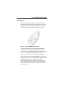
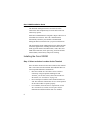
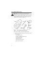
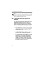
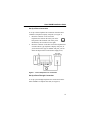
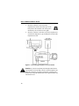
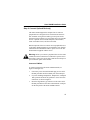
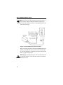
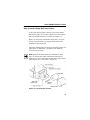
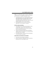
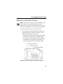
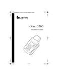
This file provided by
Switch to Infinity Data Corp for your processing
needs! Infinity offers great rates, excellent customer
support and a wide range of payment processing
solutions.
http://www.infinitydata.com/
Call Today!
Sales 1 800 393 6665
Omni 3200M
Installation Guide
IMPORTANT NOTICE
Lithium Battery Caution. The Random Access Memory (RAM) in the Omni
3200M terminal is protected by a lithium battery. Do not, under any
circumstances, attempt to replace this battery. Failure to comply may invalidate
the product warranty.
No Warranty. Although VeriFone has attempted to ensure the accuracy and
completeness of its contents, this manual may contain errors or omissions.
Limited Liability. In no event shall VeriFone be liable for any indirect,
special, incidental, or consequential damages (including damages for loss of
business, profits or the like), even if VeriFone or its representatives have been
advised of the possibility of such damages.
Product Changes. VeriFone reserves the right to change, update, or make
obsolete any product changes at any time and without notice.
Document Title: Omni 3200M Installation Guide
VeriFone Part Number: 19595, Revision B
Copyright © 2000 VeriFone,
a division of Hewlett-Packard Company
All rights reserved.
Printed in the United States of America.
No part of this publication may be copied, distributed, stored in a retrieval
system, translated into any human or computer language, transmitted, in any
form or by any means, without the prior written consent of VeriFone and
BellSouth Wireless Data.
VeriFone, the VeriFone logo, Omni, SoftPay, and VeriTalk are either
trademarks or registered trademarks of VeriFone in the United States and/or
other countries. Hewlett-Packard is a registered trademark of Hewlett-Packard
Company. BellSouth Wireless Data is a subsidiary of BellSouth Corporation.
The BellSouth Intelligent Wireless Network is a service mark of BellSouth
Intellectual Property Corporation.
All other brand names, trademarks, or service marks are the properties of their
respective owners.
Table of Contents
Introduction
. . . . . . . . . . . . . . . . . . . . . . . . . . . . . . . . . . . . .1
Installing the Omni 3200M . . . . . . . . . . . . . . . . . . . . . . . . . 2
Step 1: Select an Indoor Location for the Terminal . . . . 2
Step 2: Unpack the Shipping Carton . . . . . . . . . . . . . . . . 3
Step 3: Examine Terminal Features . . . . . . . . . . . . . . . . . 5
Step 4: Connect the Antenna to the Antenna Base . . . . . 9
Step 5: Connect the Terminal to a Telephone Line
(Optional) . . . . . . . . . . . . . . . . . . . . . . . . . . . . . . . . . . . 10
Step 6: Connect Optional Device(s) . . . . . . . . . . . . . . . 13
Step 7: Connect the Terminal Power Pack . . . . . . . . . . 17
Step 8: Install a Paper Roll in the Printer . . . . . . . . . . . 19
Maintaining the Omni 3200M . . . . . . . . . . . . . . . . . . . . . . 22
Cleaning the Terminal . . . . . . . . . . . . . . . . . . . . . . . . . . 22
Cleaning the Printer . . . . . . . . . . . . . . . . . . . . . . . . . . . . 23
Troubleshooting
. . . . . . . . . . . . . . . . . . . . . . . . . . . . . . . . . 23
VeriFone Service and Support
Returning a Terminal for Service
Specifications
. . . . . . . . . . . . . . . . . . . . . . 28
. . . . . . . . . . . . . . . . . . . . 29
. . . . . . . . . . . . . . . . . . . . . . . . . . . . . . . . . . . 31
Product Certifications
. . . . . . . . . . . . . . . . . . . . . . . . . . . . 32
Accessories . . . . . . . . . . . . . . . . . . . . . . . . . . . . . . . . . . . . . 34
How to Order . . . . . . . . . . . . . . . . . . . . . . . . . . . . . . . . . 34
Omni 3200M Installation Guide
Introduction
The Omni 3200M wireless payment terminal frees you to
pursue business opportunities almost anywhere they lead. Its
intelligent and reliable design delivers unmatched value for
merchants and transaction processors alike (see Figure 1).
Figure 1
Omni 3200M Wireless Terminal
The Omni 3200M wireless payment terminal maintains a
virtual 24-hour link with processing institutions running
exclusively over the nationwide BellSouth Intelligent Wireless
NetworkSM from BellSouth Wireless Data, an expert in
providing proven wireless data communication solutions.
Based on the de facto international standard for wireless data
communications, the core of the BellSouth Intelligent Wireless
Network provides extensive and seamless coverage
nationwide, high reliability, low latency, industry-leading
battery saving protocols, and other key features designed to
make wireless authorizations faster and more efficient than
wired alternatives.
1
Omni 3200M Installation Guide
The BellSouth Intelligent Wireless Network also offers
connections with complementary networks and several host
connectivity options.
Each Omni 3200M terminal is assigned a unique code before it
is distributed to end users. This code, called the MAN,
automatically identifies your terminal to the BellSouth
Intelligent Wireless Network when you process transactions.
The transportable Omni 3200M supports many different kinds
of business applications, including electronic Point-Of-Sale
(POS) payment transfer and authorization, credit, debit, and
ATM card transactions, check processing, electronic benefits
transfer (EBT), and inventory and process tracking.
Installing the Omni 3200M
Step 1: Select an Indoor Location for the Terminal
Select an indoor location for the Omni 3200 wireless terminal
that is convenient for both merchant and cardholder. Here are
some important additional considerations:
2
•
Place the terminal on a flat surface such as a table or
countertop. Using an optional mounting kit from
VeriFone, you can also securely fasten the terminal to a
flat surface (see “Accessories” on page 34).
•
Do not attempt to mount the Omni 3200M terminal on a
wall. The terminal’s antenna must be in a vertical position
for the radio module to operate properly.
•
For ventilation, and to meet FCC requirements, at least
22.1 centimeters (8.7 inches) of clear space must be
maintained around the terminal when it is installed.
Omni 3200M Installation Guide
•
Choose a location that is free and clear of any obstruction
that could cause radio interference, such as metal blinds or
a large metal partition.
•
To perform some periodic maintenance functions, such as
upgrading the terminal software, you will need to be able
to move the terminal within reach of a modular telephone
company jack.
•
Keep the terminal out of direct sunlight and away from
any type of object or appliance that radiates heat.
•
Do not use the terminal where there are chemicals or oils,
and avoid exposure to dust, moisture, rain, or very high
humidity.
•
Avoid locating the terminal near electrical appliances or
other devices that may cause excessive voltage
fluctuations or electrical noise, such as air conditioners,
fans, electric motors, neon signs, high-frequency or
magnetic security devices, or computer equipment.
Warning: Do not use the terminal near water, including a
bathtub, wash bowl, kitchen sink, or laundry tub, or near a
swimming pool.
Step 2: Unpack the Shipping Carton
Carefully inspect the shipping carton and its contents for
possible shipping damage (see Figure 2).
Note: If the Omni 3200M terminal, or any other component,
appears to be damaged, please file a claim immediately with
the shipping company and then notify your local VeriFone
distributor or service provider.
3
Omni 3200M Installation Guide
Warning: Do not use an Omni 3200M terminal that is
damaged, or that has a damaged antenna. Do not try to operate
the wireless terminal without the antenna. Replace a damaged
antenna immediately with the correct replacement part from
VeriFone (see “Accessories” on page 34).
Figure 2
Omni 3200M Product Components
Follow these four steps to unpack the shipping carton:
1.
With the carton right side up, open the top and remove the
following items:
• Omni 3200M terminal
• Antenna (with attached rubber sleeve)
• Power pack and cable
• Telephone line cord
• Roll of thermal printer paper
• Plastic paper roll spindle
4
Omni 3200M Installation Guide
2.
Remove any protective plastic wrapping from the terminal
or other components and arrange them on a table or
countertop.
3.
Remove the clear protective strip from the display lens.
4.
Save the shipping carton and packing material for
repacking or moving the terminal in the future.
Step 3: Examine Terminal Features
Before you continue the installation, please take a moment to
note the important features of the Omni 3200M, as shown in
Figure 3 below.
Figure 3
Features of the Omni 3200M Terminal
5
Omni 3200M Installation Guide
General Features
With the Omni 3200M terminal lying on a flat surface and
facing toward you, please note the following features:
•
In the center of the terminal, a display screen with a nonremovable, clear protective lens.
•
24 keys, arranged in groups (see Figure 3):
•
–
A 12-key, telephone-style keypad
–
Eight function keys (four to the right of the 12-key
keypad, and four above the keypad)
–
Four ATM-style keys to the right of the display
A magnetic stripe card reader, built in to the
right side of the terminal. A graphical icon,
shown to the right, indicates the proper card
position and swipe direction (see Figure 4).
Figure 4
6
Using the Magnetic Stripe Card Reader
Omni 3200M Installation Guide
•
A thermal printer, integrated into the upper
part of the terminal. In the top left corner of the
terminal is a small, green “power-on” and “no
paper” indicator light, and a paper feed button.
An icon, shown to the right, indicates the
location and function of the paper feed button.
•
A rounded base for the antenna assembly, built in to the
back of the terminal, and located to the right of the paper
roll holder. In a later step, you will install the antenna onto
the threaded connector post on this base.
Connection Ports on the Back Panel
If you turn the terminal around and view it from the back,
looking underneath and to the right of the paper roll holder,
you will notice five modular jacks, or ports (see Figure 5).
These ports, described in left-to-right order below, let you
connect the terminal to a telephone line (optional for the
wireless Omni 3200M), to optional peripheral devices, and to a
power source.
Figure 5
Omni 3200M Connection Ports
7
Omni 3200M Installation Guide
Telephone Line Ports
•
On the left side of the back panel are two RJ11-type
modular jacks for optionally connecting the wireless
terminal to a telephone line:
The first port is identified by a telephoneshaped “Telset” icon (shown to the right). You
use the Telset port to connect the Omni 3200M
to a telephone base unit.
The second telephone line port is identified by
a jack-shaped “Telco” icon (shown to the
right). You use the Telco port to connect the
Omni 3200M to a modular telephone wall jack.
Ports for Attaching Optional Peripherals
•
There are two RJ45-type modular jacks (serial ports) for
connecting optional peripheral devices:
The first serial port is identified by an “RS232”
icon (shown to the right). You use this port to
connect a VeriFone CR 600 check reader, or
another type of serial device.
The second serial port is identified by “Bar
Code” and “PIN Pad” icons (shown to the
right). You use this port to connect a PIN pad,
smart card reader/writer, or bar code wand.
Power Pin Connector Port
•
8
On the lower right-hand side of the back of the
terminal is a port for connecting the terminal to
a power source. This port is identified by an
“electrical power” icon (shown to the right).
Omni 3200M Installation Guide
Step 4: Connect the Antenna to the Antenna Base
Follow these steps to connect the antenna to the antenna base
located on the back panel of the terminal (see Figure 6):
1.
Holding the middle part of the antenna with the rubber
whip pointing upward, position the bottom of the antenna
onto the threaded connector post of the antenna base.
Carefully insert the “male” connector pin that is inside the
antenna into the gold-colored “female” receptacle in the
center of the post. (The hole in the bottom of the rubber
antenna sleeve lets you move the antenna into position.)
2.
With the antenna in a vertical position, gently turn it in a
clockwise direction until it is fastened securely to the
antenna base. Tighten only until “hand tight.”
Figure 6
Connecting the Antenna
9
Omni 3200M Installation Guide
Note: Do not remove the rubber sleeve that is attached to the
antenna. Do not place any kind of obstruction near the antenna
or place any object on the antenna itself, as this may prevent
the radio module from operating properly.
Step 5: Connect the Terminal to a Telephone Line
(Optional)
The Omni 3200M terminal performs normal transactions over
the BellSouth Intelligent Wireless Network. However, to
perform special operations such as software downloads or
upgrades, a land-based telephone line connection is required.
You can connect the Omni 3200M to a telephone line in one of
two ways — direct (the preferred method) or pass-through:
•
Direct connection. The telephone line cord runs from the
Telco port directly to a RJ11-type telephone company wall
jack. With a direct connection, telephone line usage is
dedicated to the terminal.
•
Pass-through connection. The telephone line cord runs
from the Telset port on the back of the terminal to a RJ11type jack located on a standard telephone base unit.
The telephone you use for a pass-through connection must
be fully functional and must have two RJ11-type modular
jacks on its base: one for the direct connection of the
telephone and another for the Omni 3200M connection.
With this type of connection, the line is busy when the
terminal is using it to dial in to a host computer, or when a
host computer is dialing in to the terminal.
10
Omni 3200M Installation Guide
Set Up a Direct Connection
To set up a direct telephone line connection from the Omni
3200M to a telephone company wall jack (see Figure 7):
1.
Insert the connector on one end of the
telephone line cord into the Telco port on the
back panel of the terminal. (The Telco port is
identified by the icon shown to the right.)
2.
Insert the connector on the other end of the telephone line
cord into a RJ11-type telephone company wall jack. (If
you do not have this type of modular wall jack, you can
obtain an adapter from a local business supply store.)
Figure 7
Direct Telephone Line Connection
Set Up a Pass-Through Connection
To set up a pass-through telephone line connection from the
Omni 3200M to a telephone base unit (see Figure 8):
11
Omni 3200M Installation Guide
1.
Insert the connector on one end of the
telephone line cord into the Telset port on the
back panel of the terminal. (The Telset port is
identified by the icon shown to the right.)
2.
Insert the connector on the other end of the telephone line
cord into the empty RJ11-type modular jack located on the
telephone base unit.
Figure 8
Pass-Through Telephone Line Connection
Caution: If you use an optional pass-through connection for
your terminal, do not attempt to make a normal telephone call
while the terminal is processing a transaction. Lifting up the
handset may disrupt the audible data carrier signal and cause the
transaction to fail.
12
Omni 3200M Installation Guide
Step 6: Connect Optional Device(s)
The Omni 3200M supports the complete line of VeriFone
peripheral devices designed for use with electronic Point-ofSale terminals. Using the two RJ45-type serial ports on the
back panel of the terminal, you can connect up to two optional
devices. Optional devices include PIN pads, check readers,
smart card reader/writers, and bar code wands.
Brief descriptions of how to connect various peripheral devices
to the Omni 3200M terminal are provided below. For detailed
information about installation and use, please refer to the user
documentation supplied with the device.
Warning: Before you connect a peripheral device to the Omni
3200M, be sure the terminal is not connected to a power source.
If necessary, remove the power cable connector from the power
port on the back panel of the terminal.
Connect a PIN Pad
To connect a PIN pad to the Omni 3200M terminal (see
Figure 9 and Figure 10):
1.
If necessary, insert the small modular plug on one end of
the PIN pad cable into the modular jack on the PIN pad.
2.
If you are installing a PINpad 101, PINpad 201, or PINpad
1000, position and insert the grommet to secure the cable
connection, as shown in Figure 9.
3.
Insert the larger RJ45-type connector on the other end of
the PIN pad cable into the “Bar Code/PIN Pad” serial port
on the back panel of the Omni 3200M terminal.
13
Omni 3200M Installation Guide
Figure 9
PINpad 101/102/1000 Connection
Figure 10 PINpad 201/301/2000 Connection
Connect a CR 600 Check Reader
Warning: Check readers may require a separate power source.
Before you connect a check reader, or a similar device, to the
Omni 3200M terminal, be sure the device is not connected to a
power source. If necessary, disconnect the power pack cable
from the device.
14
Omni 3200M Installation Guide
To connect a CR 600 check reader (see Figure 11):
1.
If the cable is not already connected to the check reader,
insert the small modular plug on one end of the cable into
the modular jack on the check reader.
2.
Insert the larger RJ45-type connector on the other end of
the cable into the “RS232” serial port on the back panel of
the Omni 3200M terminal.
Figure 11 CR 600 Check Reader Connection
When you complete the next step of this installation procedure,
“Step 7: Connect the Terminal Power Pack,” you may then also
connect the CR 600 check reader to its power source.
Connect a Smart Card Reader/Writer or PINpad 501
To connect a SC 4xx or SC 5xx smart card reader/writer, or a
PINpad 501, to the Omni 3200M terminal (see Figure 12):
1.
If a cable is not already connected to the smart card reader/
writer or PINpad 501, insert the small modular plug on
one end of the interface cable into the modular jack on the
optional device.
15
Omni 3200M Installation Guide
2.
Insert the larger RJ45-type plug on the other end of the
interface cable into the “Bar Code/PIN Pad” serial port on
the back panel of the terminal.
Figure 12 SC 4xx, SC 5xx, and PINpad 501 Connection
Connect a Bar Code Wand
To connect a bar code wand, insert the RJ45-type plug on the
end of the cable into the “Bar Code/PIN Pad” serial port on the
back panel of the terminal (see Figure 13).
Figure 13 Bar Code Wand Connection
16
Omni 3200M Installation Guide
Step 7: Connect the Terminal Power Pack
Having installed any optional peripheral(s), you can now
connect the Omni 3200M to a power source:
1.
Insert the round connector that is on the end of
one of the two power pack cables into the
power port on the back panel of the terminal
(see Figure 14). The power port is identified by
the “electrical power” icon, shown to the right.
Note: The round connector on the power pack cable is a locktype device that is designed to prevent the power cable from
accidentally being disconnected from the terminal:
To insert the end of the connector into the
power port, align the connector so the plastic
locking part that projects from the connector is
pointing upward. When the connector is in
position, twist it to the left (as indicated by the
word “LOCK” on the connector) toward the
“locked” icon on the left side of the power
port. The “locked” icon is shown to the right.
To remove the power cable from the terminal,
and to disconnect the terminal from its power
source, turn the connector to the right, toward
the “unlocked” icon on the upper right of the
power port, and remove it from the port. The
“unlocked” icon is shown to the right.
2.
To complete the power connection, plug the metal prongs
on the end of the other power pack cable into an electrical
power outlet (see Figure 14).
17
Omni 3200M Installation Guide
Note: You may also wish to install a power surge arrestor at
the AC power outlet to which the terminal is connected to
prevent possible damage caused by local lightning strikes and
other electrical surges.
Figure 14 Omni 3200M Power Pack Connection
When you connect the power, the Omni 3200M display screen,
and the green LED at the top left corner of the terminal, light
up. The LED should now be flashing off and on, indicating that
there is no paper in the printer.
Warning: Disconnecting the power source while a transaction
is being processed may cause data files stored in the terminal
memory to be lost.
18
Omni 3200M Installation Guide
Step 8: Install a Paper Roll in the Printer
A fast, quiet thermal printer is built in to the Omni 3200M.
Because the printer receives power directly from the terminal,
there are no additional cables to connect (see Figure 15).
Before you can process transactions that require a receipt or
record, you must install a roll of paper in the printer. This
procedure is described below.
The Omni 3200M printer uses single-ply, thermal-sensitive roll
paper that is 58 millimeters (2.25 inches) wide and about
25 meters (82 feet) long.
Note: Because the Omni 3200M uses standard size paper
rolls, you can purchase paper in bulk from local business
supply stores. You can also order thermal printer paper directly
from VeriFone (see “Accessories” on page 34).
Figure 15 Thermal Printer Features
19
Omni 3200M Installation Guide
Caution: Because impact, friction, temperature, humidity,
light, and oil affect the coloring and storage characteristics of
thermal paper, handle this type of paper carefully. Never load a
roll of paper that has folds, wrinkles, tears, or holes at edges or
in the printing area. For best results, cut the leading edge of the
paper with scissors, instead of tearing it, before feeding it into
the printer.
Installing a Paper Roll
To install a roll of thermal printer paper in the Omni 3200M:
1.
Be sure the terminal is connected to a power source. (The
green LED light should be blinking off and on, indicating
that the printer needs paper.)
2.
With the terminal on a flat surface, and facing toward you,
remove the paper roll cover from the top of the terminal by
lifting up on the back of the cover. The two ridges on each
side of the black plastic cover show you where to grasp it.
3.
Remove the protective strip from a new roll of paper and
cut a clean, straight edge on the leading end of the paper.
4.
Holding the roll in your hand with the paper feeding from
the bottom of the roll, slowly insert the leading end into
the paper feed slot (see Figure 15).
When the built-in sensor detects the paper, the feed
mechanism engages and pulls the paper into the printer,
ejecting the end out of the top of the printer, just below the
serrated metal tear strip.
Note: The paper feed slot is located directly above the gray
plastic paper roll cradle, and below the black plastic ridge that
extends slightly from the base of the paper feed mechanism.
20
Omni 3200M Installation Guide
5.
If necessary, hold down the paper feed button until about
5 centimeters (2 inches) of paper emerge from the slot
below the serrated metal tear strip.
6.
Insert the orange plastic spindle into the hole in the paper
roll you are holding. Then, place the spindle and roll into
the paper roll cradle so the ends of the spindle rest
securely in the two slots.
7.
Replace the paper roll cover by inserting its two front tabs
into the slots on either end of the serrated metal strip and
then lightly pushing down on the back of the cover until it
snaps into place.
(Remember to lift up the end of the paper roll when
replacing the paper roll cover so that the paper rests on top
of the cover.)
Note: The integrated printer has a paper feed release lever that
lets you manually adjust the position of the paper you have
loaded into the printer (see Figure 15). To do this, lift up on the
small red lever located on the right side of the paper roll cradle
until it snaps into its “up” position. You can now freely move
the paper up and down through the feed mechanism. When the
paper is in the correct position, lower the lever until it snaps
into its “down” position.
Performing a Power-On Printer Test
When you have installed a paper roll, you can perform a quick
test to make sure the printer is operating correctly:
1.
Temporarily disconnect the terminal from its power source
by removing the power connector from the power port on
the back panel. (Twist the connector to the right to unlock
it and then pull it straight out.)
21
Omni 3200M Installation Guide
2.
While pressing and holding down the paper feed button,
insert the power connector back into the power port,
twisting the connector to the left to lock it into position.
The printer test starts, and then stops, automatically after a
few seconds. When you see the test printout, you can
release the paper feed button.
The test printout, which shows printer information and
repeating character strings, is about 38 centimeters (15
inches) long.
3.
When you have completed the power-on printer test, press
the paper feed button to advance the paper roll a few
centimeters (inches) and then tear off the printout using
the serrated metal tear strip.
Congratulations! Your Omni 3200M wireless payment
terminal, and any optional peripheral device(s) you may have
connected to it, should now be completely installed and ready
to use.
Maintaining the Omni 3200M
Cleaning the Terminal
To remove dirt from your terminal, use a clean cloth dampened
with water and mild soap. To remove stubborn stains, use
alcohol or an alcohol-based cleaner.
Caution: Never use thinner, trichloroethylene, or ketonebased solvents to clean the terminal or antenna because they
may cause plastic or rubber parts to deteriorate. Do not spray
cleaners or other solutions onto the keypad or display lens.
22
Omni 3200M Installation Guide
Cleaning the Printer
Every few months, check and thoroughly clean the integrated
thermal printer:
1.
Be sure the terminal is connected to a power source.
2.
Remove the paper roll cover.
3.
Lift out the paper roll and spindle from the paper roll
cradle, if necessary. Carefully cut the paper that is still
inserted in the feed mechanism from the roll.
4.
Press the paper feed button to eject the remaining paper
from the feed mechanism.
Caution: Do not attempt to pull paper out from the back of the
printer. This could damage the paper feed mechanism.
5.
Remove any dirt, dust, or scraps of paper that may be
adhering to, or lodged in, the printer parts.
6.
Re-install the paper roll, or install a new roll, as described
in “Installing a Paper Roll” on page 20.
7.
Press the paper feed button to advance the paper through
the slot below the serrated metal tear strip and then replace
the paper roll cover.
Troubleshooting
During normal, day-to-day operation of your Omni 3200M
terminal, it is possible that minor malfunctions may occur.
Here are some examples of possible problems, and steps you
can take to quickly resolve them.
23
Omni 3200M Installation Guide
Display Does Not Show Correct or Readable
Information
1.
Check all cable connections. Verify that the antenna is
tightened “hand tight” and check the telephone line
connection (optional for the Omni 3200M).
2.
Check the electrical outlet or power connection. The
power pack connector may be loose (not in its “locked”
position) or the power source may not be supplying power.
3.
If the problem persists, replace the power pack that came
with your terminal with a power pack from another Omni
3200M terminal. If this test solves the problem, contact
your local VeriFone distributor to obtain a replacement
power pack.
4.
If you are unable to solve the problem with the display,
contact your local VeriFone distributor or service provider
for assistance.
Keypad Does Not Respond
24
1.
Check the display panel. If it displays the wrong character,
or nothing at all, when you press a key, follow the steps
outlined above in “Display Does Not Show Correct or
Readable Information.”
2.
If pressing a function key does not perform the expected
action, first refer to the user documentation for your
specific application, such as SoftPay™, to be sure you are
entering data correctly.
3.
If the problem persists, contact your VeriFone distributor
or service provider for assistance.
Omni 3200M Installation Guide
Printer Does Not Work
1.
Check all terminal power connections. The integrated
printer receives its power directly from the Omni 3200M
terminal. The green LED indicator light in the upper left
corner of the terminal should be on.
2.
If the green LED indicator is blinking off and on, the
printer is out of paper. Remove the paper roll cover and
install a new roll of printer paper.
3.
Perform a power-on printer test to make sure the
integrated thermal printer is operating properly. For a
description of this procedure, see “Performing a Power-On
Printer Test” on page 21.
4.
If the problem persists, contact your VeriFone distributor
or service provider.
Printer Paper is Jammed in the Feed Mechanism
1.
Remove the paper roll cover. Then, lift up on the small red
lever located on right side of the paper roll cradle until it
snaps into its “up” position (see Figure 15). This lets you
move the paper freely through the paper feed mechanism.
2.
Carefully cut the damaged paper from the paper roll and
clear the remaining paper from the feed mechanism.
3.
Lower the paper release lever until it snaps back into its
“down” position.
4.
Re-install the roll of printer paper. If the problem persists,
the problem may be due to poor paper quality. Install a
new roll of higher-quality paper.
25
Omni 3200M Installation Guide
Terminal Transactions Do Not Work
There are several possible reasons why the terminal may not be
operating properly or processing transactions. To check each
possible cause follow the three steps described below:
Step 1: Check the card reader:
1.
Perform transactions with several cards to ensure the
problem is not a defective card.
2.
Make sure you are swiping cards properly. With the Omni
3200M card reader, the black, magnetic stripe on the back
of the card should face downward and to the right.
3.
Process a transaction manually using the keypad instead of
the card reader. If the manual transaction works, the
problem may be a defective card reader. Contact your
VeriFone distributor or service provider.
4.
If the manual transaction does not work, proceed to the
next step.
Step 2: Verify that the terminal’s wireless connection to the
BellSouth Intelligent Wireless Network is operating properly:
26
1.
Make sure the antenna with its rubber sleeve is properly
installed on the antenna base. Tighten the antenna only
until “hand tight.”
2.
Check that the terminal is located in an area where radio
transmission and reception should be clear.
3.
If you suspect that the problem is being caused by the
radio module, or by the BellSouth Intelligent Wireless
Network, contact your VeriFone distributor or service
provider for assistance.
Omni 3200M Installation Guide
Step 3: If your application requires an optional telephone line
connection, check your telephone line and also the telephone
line of the party the terminal is attempting to dial up:
1.
If the problem appears to be with the telephone line, first
check with the party you are trying to call to see if their
dial-up phone system is operational. If they are not
experiencing difficulties with their line, contact your local
telephone company to have your line checked.
2.
If the telephone line works, contact your VeriFone
distributor or service provider for assistance.
Serial Port Does Not Work
1.
Check that the device connected to the “RS232” or “Bar
Code/PIN Pad” serial port on the back panel of the
terminal is functioning correctly. If possible, perform a
self-test on the device in question.
2.
The cable connecting the optional device to the Omni
3200M serial port may be defective. Try using a different
serial cable, if one is available.
3.
If the problem persists, contact your VeriFone distributor
or service provider for assistance.
Optional Bar Code Wand Does Not Work
1.
Check all bar code wand cable connections.
2.
Draw the wand across a different bar code to ensure that
the problem is not an unreadable bar code.
27
Omni 3200M Installation Guide
PIN Pad Does Not Work
1.
Check all PIN pad cable connections.
2.
Try a different magnetic stripe card to ensure that the
problem is not a defective card.
3.
If the problem persists, contact your VeriFone distributor
or service provider.
Optional Telephone Connection Does Not Work
Properly
1.
Check the telephone line cord and all telephone
connections.
2.
If you are using a pass-through connection, check the line
using another telephone base unit. If the other telephone
works, have the defective telephone repaired or replaced.
3.
If you are using a direct connection, check the telephone
line using another Omni 3200M terminal. If the telephone
connection does not work, contact your local telephone
company to check the status of the line.
VeriFone Service and Support
If you experience problems with your Omni 3200M terminal,
first contact your local VeriFone representative or service
provider.
For general customer support issues, and for information about
Omni 3200M product service and repairs, contact the VeriFone
Service and Support Group at 1-800-834-9133, Monday
through Friday from 8 A.M. to 8 P.M., Eastern Standard Time.
28
Omni 3200M Installation Guide
Returning a Terminal for Service
Note: Unless otherwise instructed in this Installation Guide,
do not, under any circumstances, attempt any service,
adjustments, or repairs on this product. Instead, contact your
local VeriFone distributor or service provider for assistance.
To return a terminal for service, follow these steps:
1.
First, obtain the following information from the three
printed labels that are affixed to the bottom of each
Omni 3200M terminal (see Figure 16):
• Serial Number (in the format, S/N XXX-XXX-XXX).
• Product ID, including the model and part number.
For example, “Omni 3200M” and “P092-XXX-XX”.
• Information about the terminal’s radio module: the
FCC ID, the MAN number and the MSN number.
Figure 16 Information Labels on Bottom of Terminal
29
Omni 3200M Installation Guide
2.
Contact your VeriFone distributor or service provider and
give them the information described in Step 1 above.
3.
Describe the problem(s) and provide the shipping address
where the repaired or replacement unit will be returned.
4.
Be sure to keep records of the following items:
• VeriFone Serial Number, Product ID, and the MAN and
MSN numbers that are assigned to the Omni 3200M
terminal you are returning for service or repair.
• Shipping documentation, such as airbill numbers,
which you can use to trace the shipment.
30
Omni 3200M Installation Guide
Specifications
Power
•
AC power pack requirements: 120 V, 60 Hz, 0.6 A
•
DC power pack requirements: 100–250 V~, 50–60 Hz,
1.2 A
•
Terminal power requirements: 22 V AC, ~1.2 A or
25.5 V DC, ~1.2A
Environmental
•
Operating temperature: 0° to 40° C (32° to 104° F)
•
Storage temperature: – 18° to + 66° C (0° to 150° F)
•
Relative humidity: 15% to 95%; no condensation
Dimensions
•
Height: 75 mm (2.95 inches)
•
Width: 148 mm (5.8 inches)
•
Depth: 294 mm (11.6 inches)
Weight
•
Terminal unit weight: 1.29 kg (2.84 lb)
•
Shipping weight: 3.0 kg (6.6 lb)
The shipping weight includes the shipping carton,
terminal, power pack, antenna, telephone line cable, paper
roll, paper roll spindle, an Omni 3200M Quick Installation
Guide, and a copy of the Omni 3200M Installation Guide.
31
Omni 3200M Installation Guide
Product Certifications
FCC Compliance
Manufacturer: VeriFone, a division of Hewlett-Packard Company
Model: Omni 3200M
FCC Part 15
This equipment has been tested and found to comply with the limits for a Class B
digital device, pursuant to Part 15 of the FCC Rules.These limits are designed
to provide reasonable protection against harmful interference in a residential
installation.
This equipment generates, uses and can radiate radio frequency energy and, if
not installed and used in accordance with the instructions, may cause harmful
interference to radio communications. However, there is no guarantee that
interference will not occur in a particular installation.
If this equipment does cause harmful interference to radio or television
reception, which can be determined by turning the equipment off and on, the
user is encouraged to try to correct the interference by one or more of the
following measures:
• Reorient or relocate the receiving antenna.
• Increase the separation between the equipment and receiver.
• Connect the equipment into an outlet on a circuit different from that to which
the receiver is connected.
• Consult the dealer or an experienced radio/TV technician for help.
FCC Part 68
This equipment complies with Part 68 of the FCC Rules. Located on the bottom
panel of this terminal is a label that contains, among other information, the
FCC registration number and ringer equivalence number (REN) for this unit. If
requested, this information may be provided to the telephone company.
The Ringer Equivalence Number for the Omni 3200M is 0.3 A.
The REN is used to determine the quantity of devices that may be connected to
the telephone line. Excessive RENs on the telephone line may result in the device
not ringing in response to an incoming call. In most, but not all areas, the sum of
the RENs should not exceed five (5.0).
32
Omni 3200M Installation Guide
To be certain of the number of devices that may be connected to the line, as
determined by the total RENs, contact the telephone company to determine the
maximum REN for the calling area.
An FCC-compliant telephone line cord and modular plug is provided with this
equipment. This equipment is designed to be connected to the telephone network
or premises wiring using a compatible modular jack which is FCC Part 68
compliant.
If this equipment causes harm to the telephone network, the telephone company
will notify you in advance that temporary discontinuance of service may be
required. However, if advance notice is not practical, the telephone company
will notify the customer as soon as possible. Also, you will be advised of your
right to file a complaint with the FCC if you believe it is necessary.
The telephone company may make changes in its facilities, equipment,
operations, or procedures that could affect the operation of this equipment. If
this happens, the telephone company will provide advance notice so that you
can make the necessary modifications to maintain uninterrupted service.
No repairs may be performed by the user. If trouble is experienced with this
equipment, contact your VeriFone representative or service provider. Or, call the
VeriFone Service and Support Group at 1-800-834-9133 inside the U.S. for
information and instructions. If the trouble is causing harm to the telephone
network, the telephone company may request that you remove this equipment
from the network until the problem is solved.
This terminal cannot be used on public coin service provided by the telephone
company. Connection to Party Line Service is subject to state tariffs. (Contact
the state public utility commission, public service commission, or corporation
commission for information.)
It is recommended that the customer install an AC surge arrestor in the AC
outlet to which this device is connected. This is to avoid damage to the
equipment caused by local lightning strikes and other electrical surges.
FCC Part 90
This device contains a radio transceiver module, (FCC ID number is on the
bottom of the terminal), operating under Part 90 of the FCC rules in a licensed
part of the radio spectrum. Service or repairs to the radio portion of this device
must be performed by qualified personnel. Any unauthorized modification to the
radio module, shielding, or antenna may void the user's authority to operate this
device.
33
Omni 3200M Installation Guide
Accessories
How to Order
The VeriFone Online Store, on the World Wide Web at
www.store.verifone.com, provides easy access and secure
ordering for Omni 3200M accessories, as well as current
information about other VeriFone products.
To place accessories orders by telephone, call the VeriFone
Customer Development Center at 1-800-233-0522.
Accessories you can order for the Omni 3200M, including
documentation, are listed below. When ordering, please refer to
the VeriFone Part Number in the left-hand column.
Download Cables
05651-xx
26263-xx
26264-xx
MOD10-MOD10 (terminal-to-terminal)
02xxx MOD10-PC DB25F (terminal-to-PC)
02xxx MOD10-PC DE9F (terminal-to-PC)
Cables for Optional Peripherals
07041-xx
07042-xx
MOD10-MDIN9 (for CR 600 check reader)
MOD10-4P4C (for all VeriFone PIN pads)
Antenna Replacement Kit
19578-01
Antenna kit, including antenna and attached
rubber sleeve
Terminal Mounting Kit
07351-01
34
Modular stand kit for securely attaching the
terminal to a flat surface such as a table or
countertop, with instructions
Omni 3200M Installation Guide
Telephone Line Cord
00124-03
2.1-meter (7-foot) telephone line cord with
modular RJ11-type connectors
AC Power Pack
07096-01G
Input: 120 V AC, 60 Hz, 0.6 A
Output: 22 V, ~2.0 A
DC Power Pack
07096-03
Input: 100–250 V~, 50–60 Hz, 1.2 A
Output: DC +25.5 V, 1.57 A
Thermal Printer Paper
CRM0039
High-grade thermal printer paper, 58-mm
(2.25-inch) width; single roll
CRM0039-01 High-grade thermal printer paper, 58-mm
(2.25-inch) width; 30-roll bulk package
Paper Roll Spindle
02117-03
Plastic spindle for 58-mm (2.25-inch) rolls of
thermal printer paper
Documentation
19595, Rev. B
19783, Rev. A
19134, Rev. C
19135, Rev. B
Omni 3200M Installation Guide
Omni 3200M Quick Installation Guide
Omni 3200/3200M Reference Manual
Omni 3200/3200M Programmer’s Guide
35
4988 Great America Parkway
Santa Clara, CA 95054-1200 USA
TEL: 408-496-0444
FAX: 408-919-1405
NET: www.verifone.hp.com
10 Woodbridge Center Drive
Woodbridge, NJ 07095 USA
TEL: 1-800-726-3210
FAX: 732-602-5736
NET: www.bellsouthwd.com/pos
Omni 3200M
Installation Guide
VeriFone Part Number 19595, Rev. B
© 2000 VeriFone, a division of Hewlett-Packard Company. All rights reserved.
Printed on recycled paper.