1
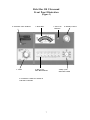
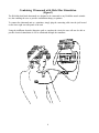
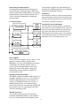
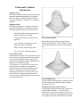
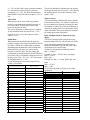
RICH-MAR 510 ULTRASOUND
OPERATION HANDBOOK AND MANUAL
Part # MN2440
Rev. E
Batch 000
CAUTION
This device is not designed to be connected with any electrical equipment unless manufactured and
approved by Rich-Mar.
NOTE: This includes whirlpools and accessories NOT manufactured by Rich-Mar. These include patient
lead cords, self-adhesive electrodes, and carbon electrodes.
CAUTION: When using carbon electrodes with any Rich-Mar stimulator, a moistened interface (cloth
or sponge) MUST be utilized between these electrodes and the patient to avoid skin irritation and/or
electrical burns.
TABLE OF CONTENTS
Rich-Mar 510 Warranty.....................................................4
Ultrasound Indications for Treatment.................................5
Ultrasound Contraindications & Warnings.........................5
Functions of Controls.........................................................6
Ultrasound Operation.........................................................6
Front Panel Illustration.......................................................7
Combining Ultrasound with Rich-Mar Stimulation.............8
Ultrasound Calibration & Tuning Procedure.......................10
Troubleshooting Guide.......................................................11
Rich-Mar 510 Specifications..............................................11
Appendix A
Ultrasound Technical Information
Appendix B
Rich-Mar 510 Parts List
Appendix C
Rich-Mar 510 Schematics
LIMITED WARRANTY
This equipment is sold under an exclusive three-year warranty from date of sale, which warrants it to
be free from defects in material and workmanship. We agree to repair or replace at the point of
manufacture, without charge, all parts showing such defects, provided the unit is delivered to us,
prepaid to our factory, intact for our examination, within three years from date of sale, and provided
such examination discloses in our final judgement that it is defective.
This warranty does not apply if the equipment has been subject to misuse, neglect, accidents, incorrect wiring (not our own), improper installation, or put to use in violation of instructions furnished by
us, has been damaged by excess voltage or has been repaired or altered outside our factory or if the
equipment has had its serial number altered or removed.
Changes: Rich-Mar reserves the right to modify or change the equipment in whole or in part, at any
time prior to delivery, in order to include refinements deemed appropriate by the Company but without incurring any liability to modify or change equipment previously delivered, or to supply new
equipment in accordance with earlier specifications. This warranty will be honored only if the enclosed card is filled out and returned to the factory. This warranty is valid only to original purchaser.
This warranty is expressly in lieu of all other warranties expressed or implied including the warranties
of merchantability and fitness for use and all other obligations on our part, and we neither assume, nor
authorize any other person to assume for us, any other liability in connection with the sale or use of
this equipment. In no event shall we be liable for consequential or special damages. We make no
warranty whatsoever in respect to accessories or parts not supplied by us.
4
Ultrasound Indications for Treatment
(Therapeutic Ultrasound)
Rich-Mar Ultrasound devices are indicated to produce therapeutic deep heat for the following conditions:
1) Relief of pain.
2) Muscle spasms.
3) Joint contractures.
But not for the treatment of malignancies.
WARNING - Federal law restricts this device to sale by or on the order of a physician or any other practitioner
licensed by the law of the state in which said person practices.
Ultrasound Contraindications
Contraindications
Ultrasound should not be used in the following areas:
1) Near or over the heart.
2) Near or over the eyes.
3) On the head.
4) Near or over reproductive organs.
5) On the lower back during pregnancy or over the pregnant uterus.
6) Directly over the spinal column.
7) Over growing bone in children.
8) Where the skin suffers from any sensory impairment.
9) Over areas of malignancies.
10) In the area of visceral plexus and large autonomous ganglion.
11) Over the thoracic area if the patient is using a cardiac pacemaker.
12) Over a healing fracture.
13) Over ischemic tissues in individuals with vascular disease where the blood supply would be unable to
follow the increase in metabolic demand and tissue necrosis might result.
Precautions
Precautions should be taken when used:
1) Over anesthetized areas.
2) On patients with hemorrhagic diastheses.
3) Ultrasound treatment should not be performed over an area of the spinal cord following laminectomy (i.e.when major covering tissues have been removed).
Caution
1) Excessive doses of ultrasound may cause damage to tissue. Periosteal pain is an indication of excess intensity and if it occurs, the power should be reduced; the transducer should be moved more rapidly over the area
being treated; or a lower pulsed duty cycle should be used.
2) If the soundhead has been operated unloaded for an extended period of time, the transducer will get hot. If
the soundhead is applied to the patient while the transducer is hot, a burn may result.
Warning
Do not operate the soundhead in an unloaded condition. It is possible that unrepairable damage may occur to
the transducer in an unloaded state.
5
Rich-Mar 510 Ultrasound
Operation
Functions of Controls (See Figure 1)
1) Timer: The timer serves as the main power
switch for the unit and allows the operator to set
the desired treatment time. Once the timer has
been activated, AC power is supplied to the unit.
Once the timer reaches zero, AC power is
interrupted and the treatment is terminated. The
panel indicates the treatment time remaining.
2) Ultrasonic Active Indicator: This light, when
on, informs the user that ultrasound is either
ready to be emitted or is currently emitting from
the transducer.
3) Power On Indicator: This light informs the user
that the timer has been activated and that AC
power is being supplied to the unit.
4) Duty Cycle/ Pulse Rate Switch: This switch
allows the operator to select either a 100% duty
cycle or one of six other pulsed duty cycles. The
pulsed duty cycles are expressed in either
percentage duty cycle or pulses per second.
5) Duty Cycle/ Pulse Rate Indicators: These
lights give the operator a linear, visual indication
of the duty cycle in which the unit has been set.
6) Intensity Control: This allows the operator to
increase and decrease the ultrasound output
intensity to obtain the desired treatment.
7) Wattmeter: Indicates the ultrasound output
being produced by the unit. The upper black
scale reads the output in total watts produced by
the largest transducer (30-510). The lower black
scale reads the output in total watts produced by
the smallest transducer (15). The center blue
scale reads the output produced in peak watts
per square centimeter and is common to both
transducers.
8) Cradle: Each transducer cradle operates a
switch that will shut off the signal to the transducer. When the transducer is set in its cradle the
ultrasound output will be shut off until the
transducer is removed.
(See Figure 1)
Before activating the timer be sure that the Intensity
Control (6) is turned fully counterclockwise. The unit
is then activated by setting the desired treatment time
into the Timer (1). Once the timer is activated the
Power On Indicator (3) will be illuminated.
Select either transducer and remove it from the
Cradle (8). The Ultrasonic Active Indicator (2) will
then be illuminated. (NOTE: The Rich-Mar 510
ultrasound will not output ultrasound with both
transducers removed from the cradles.)
Next, select the desired duty cycle with the Duty
Cycle/ Pulse Rate Switch (4). Once the proper duty
cycle has been selected the corresponding Duty
Cycle/ Pulse Rate Indicator (5) will be illuminated.
The ultrasound output intensity can now be increased
to the required level with the Intensity Control. The
intensity level will now be indicated on the Wattmeter (7).
NOTE: When administering an ultrasound treatment,
be sure the treatment area of the patient has an ample
quantity of Rich-Mar lotion or gel as a coupling
medium. The quality and quantity of the coupling
medium has a direct bearing on the amount of ultrasound energy transmitted to the treatment area.
NOTE: Even though this device is equipped with an
output failure diagnostic feature, Rich-Mar Corporation recommends that you perform the following on a
daily basis:
Before starting treatment, the operator should check
the output of the unit by placing some water or
coupling agent on the sounded and increasing the
intensity. The ultrasonic output of the unit should then
show cavitation (bubbling).
NOTE: The Model 510 ultrasound will not output
ultrasound with both transducers removed from the
cradles. One transducer must remain in the cradle at
all times in order to receive ultrasonic output.
6
Rich-Mar 510 Ultrasound
Front Panel Illustration
(Figure 1)
2. Ultrasonic Active Indicator
1. Timer
3. Power On
Indicator
7. Watt Meter
5. Duty Cycle/
Pulse Rate Indicator
8. Transducer Cradles are located on
both sides of the unit.
7
6. Intensity Control
4. Duty Cycle/
Pulse Rate Switch
Combining Ultrasound with Rich-Mar Stimulation
(Figure 2)
The Rich-Mar dual head ultrasounds are designed to be connected to any Rich-Mar muscle stimulator, thus enabling the user to provide combination therapy to patients.
To connect the ultrasound unit to a stimulator, simply plug the connecting cable into the jack located
on the lower right rear side panel of the unit.
Using the indifferent electrode (dispersive pad) to complete the circuit, the user will now be able to
provide electrical stimulation as well as ultrasound through the transducer.
8
Disinfecting Recommendations
To disinfect the soundhead between therapy treatments, Rich-Mar recommends using a disinfectant
cleaner for ultrasound. OSHA addresses the need for
prudent infection control (OSHA Instruction CPL 22.44C) to include decontamination of equipment
between patients.
sized oscillator, amplifies this signal and then lowpass filters the amplified signal prior to providing the
oscillation to the transducer element.
Transducers
Each transducer consists of a lead-zirconate-titanate
piezo-electric device which converts electrical energy
(from the main RF generator) into acoustical energy
in the form of mechanical vibrations.
Circuit Description
Front Panel Controls and Displays
The front panel of the unit provides a synchronous
motor timer for accurate treatment times, a meter for
accurate dosage (both in total power and intensity),
and a pulse rate control for the selection of seven
different pulse rates and duty cycles. Also contained
on the front panel control is a indicator showing the
ultrasound is active, and that the power is on.
Power Supplies
There are two power supplies. One is a fixed +12 Volt
supply for necessary circuitry, and the other is
adjustable to +40 Volts. The adjustable power supply
is dedicated to the main RF generator. This, in
essence, adjusts the output intensity of the device.
Digital logic circuits select proper voltage range
automatically to match whichever transducer is
selected by the operator.
Digitally Synthesized Oscillator
The digitally synthesized oscillator (DSO) provides an
ultrastable, adjustable, low-level (+12V) oscillator to
match the optimum frequency of the transducer. It
consists of a 2048kHz microprocessor crystal, an
adjustable digital divider, and a phase-lock-loop
circuit. This provides for extremely high stability both
long and short term. The output signal is then delivered to the main RF generator.
Main RF Generators
The main RF generator provides the sinusoidal
oscillation and adjustable intensity to the transducer.
It receives its input signal from the digitally synthe-
9
Annual Calibration
R3 and R40 on the main board are used to set the
right transducer, R13 and R42 are used to set the left
transducer.
Ultrasound Calibration and
Tuning Procedure
Ultrasound Service Information
Rich-Mar Corporation recommends that all RichMar ultrasonic therapy products be returned to the
factory or to a servicing Rich-Mar distributor for
service or calibration. It is recommended that the
device be calibrated annually or when any major
component is changed.
1)
2)
3)
Place the transducer under test in an Ohmic
UPM-30 watt meter, or equivalent.
Increase the intensity of the unit to its maximum.
The unit should be emitting between 25.8-30
watts for the 10cm2 transducer and 12.9-15 for
the 5cm2 transducer. If this is not the case,
perform the Full Calibration procedure listed in
the following the section.
Adjust R40-R42 such that the correct front
panel scale corresponds to the output of the
unit.
Caution
Calibration and peaking adjustments must not be
attempted unless the person performing these adjustments has the proper test equipment, which must
include an acceptable ultrasonic wattmeter, such as
the Ohmic UPM-30 or equivalent. Degassed water
must be used to obtain accurate readings.
4)
Warning
Use of controls or adjustments or performance of
procedures other than those specified herein may
result in hazardous exposure to ultrasonic energy.
Calibration of the unit is now complete. Check the
accuracy of the unit at 30, 15, 5 watts for the 10cm2
side and 15, 10, 5 watts for the 5cm2 side. The
tolerance allowed by the FDA is 20% in either
direction.
These controls are as follows:
Main Board
R3 – Sets the maximum power output for the
10cm2 transducer.
R40- Calibrates the upper scale of the front
panel meter.
R21- Controls the “Ultrasonic Active LED”.
This must be adjusted using the 5cm2 transducer.
R23- This also controls the “Ultrasonic
Active LED”. This must be adjusted using
the 5cm2 transducer.
R13- Sets the maximum power output for the
5cm2 transducer.
R42 – Calibrates the lower scale of the front
panel meter.
RF Deck
SW1- Peaking adjustment – “rough tuning”
SW2- Peaking adjustment – “fine tuning”
10
Full Calibration Procedure
1) Remove metal hole plugs from rear of unit.
2) Rotate the front-panel intensity knob to its
maximum setting (fully clock-wise). Adjust R3
and R40-R13 and R42 fully clockwise.
3) Place transducer under calibration in a UPM-30
wattmeter and set the balance ready to read 3010cm 2 watts and 15-5cm2 watts.
4) Adjust R3-R13 counter clockwise until the unit is
emitting 30 watts -10cm2 and 15 watts - 5cm2 .
5) Adjust R40-R42 counter clockwise until the
front-panel meter reads 30 watts - 10cm2 scale
and 15 watts - 5cm2 scale.
Calibration of the unit is now complete. Check the
accuracy of the unit at 30, 15, and 5 watts for the
10cm2 side and at 15, 10, and 5 watts for the 5cm2
side. Tolerance allowed by the FDA is 20% in either
direction.
Tuning (Peaking) Procedure
Trouble-Shooting
(NOTE: This will only be required if the transducer or
portions of the RF generator have been changed.)
Place the transducer requiring peaking in a wattmeter.
Increase the front-panel intensity until the pointer is
about one-half of its full intensity (pointer straight
up). Turn the unit on, and place in the continuous
setting.
Listed below are several options for troubleshooting
the Rich-Mar Model 510 Ultrasound. If these solutions fail to remedy the problem, please call the RichMar Service Department at 1-800-762-4665.
1)
2)
3)
4)
Adjust the switch to the left on the oscillator
board until the maximum deflection (maximum
output) is achieved on the wattmeter. The
crystal is now “roughly” peaked.
Decrease the switch position by one (i.e.- if the
switch was on “6”, put in “5” position). Now set
the rear switch at “0”. Begin to increment the
switches in numerical order until the maximum
power is reached. (Example: 50, 51, 52,…58,
59, 60, 61, 62 is found to be the maximum
because at 63 the power begins to decrease.)
Add five to the maximum, and set the
switches accordingly. (Continuing as described
above, set the switch position to 67.)
Continue with the Full Calibration Procedure.
Ultrasonic Active Setting
Procedure
(NOTE: This procedure must be done using the small
transducer.)
1)
Set maximum output and meter output
reading.
2)
Turn intensity pot down until meter reads 2
watts on top scale of meter.
3)
Switch selector switch to 10%, adjust R23
fully clockwise, turn R21 counter clockwise
until UA light goes out (if light is already out
go to next step).
4)
Adjust R21 clockwise until UA light comes
on.
5)
Unplug SH from deck and turn intensity up
until meter reads 3.0 watts on top scale of
meter.
6)
Adjust R23 counter clockwise until UA light
comes on, turn intensity to 3.5 watts and UA
light should go out. If UA light does not
extinguish, repeat step 6.
1.) Unit fails to turn on.
Check power cord for full installation.
Check fuse.
Check timer connections.
2.) Ultrasonic active indicator fails to illuminate.
Check to see that the cradle is in the upright position.
Check internal cable connection.
Check “Ultrasonic Active” setting.
Check LED.
3.) Meter won’t advance.
Check to see that the cradle is in the upright position.
Check meter connection.
Check voltage supply.
4.) Meter reads very low level and there is no
“Ultrasonic Active” light on
Check to see that the opposite cradle is
in the down position and that opposite transducer
is hung up properly.
Check to see that the cradle is in the upright
position.
Model 510 Specifications
Input:
120VAC, 60Hz, 1.5 amp
220VAC, 50Hz
Dimensions:
W-14.25”/35.6cm
D-9.125” 22.8cm
H-5”/12.5cm
Weight:
15 lbs/6.75kg
11
APPENDIX A
ULTRASOUND TECHNICAL INFORMATION
Ultrasound Technical
Information
Applicator Type:
The ultrasonic radiation fields produced by Rich-Mar
therapeutic ultrasound transducers are of the plane
wave type and are essentially cylindrical in shape.
This type of applicator is referred to as a collimating
applicator.
Applicator Label:
Each Rich-Mar applicator is labeled to provide the
user with information on its applicable parameters.
The following abbreviations are used on the label.
Gen: The Rich-Mar ultrasonic generator for
which the applicator is intended.
f: The operating frequency in MHz for the
applicator.
Area: The effective radiating area of the
applicator in square centimeters.
BNR: The Beam Nonuniformity Ratio.
Near Field Distribution
Beyond this point, the beam has a more uniform
intensity and is called the “far field”. Below is shown
the far field distribution at 16cm from the transducer
face.
Type: Coll-means collimating applicator.
Near Field/ Far Field
If measurements are made of the sound intensity along
the central axis of the beam produced by the applicator, the intensity distribution shows maxima and
minima near the applicator and then a gradual decline
beyond the last maximum intensity.
The “interference” or “near field” is the area in the
ultrasound beam extending from the applicator
surface to the location of the most distant intensity
maximum. In this area, maxima and minima of
intensity are located close to each other. This is the
area in which most therapeutic application occurs.
This is shown in the following figure measured 0.5cm
from the transducer face.
Far Field Distribution
The preceding descriptions apply for radiation emitted
into the equivalent of an infinite medium of distilled,
degassed water at 30o C.
Transducer Parameters and Tolerances:
The Rich-Mar ultrasound units operate at frequencies
of either 1MHz or 3MHz +/- 10%. The effective
radiating areas (ERA) of the transducers are ten, five,
or two square centimeters, depending upon the size of
the transducer being used. The tolerance for the ERA
is +/- 25% on the 2 and 5 square centimeter transducers. The tolerance for the 10 square centimeter
transducers is +0, -25%. The Beam-NonuniformityRatio (BNR) for any Rich-Mar transducer is 5.5:1 or
less.
100% Mode
When operated in the 100% mode, the generator
produces a non-interrupted sinusoidal waveform of
one or three MHz. The peak power and average
power are therefore the same.
The error in indication of radiated power in intensity
for the continuous mode does not exceed +/- 14%
allowing for a 6% error in the wattmeter, which
equals +/- 20%.
Pulsed Mode
When operated in the pulsed mode, the generator
produces a square-wave burst of sinusoidal waveform
of 1MHz or 3MHz of 2.5 milliseconds in duration.
Depending upon the Rich-Mar model of therapeutic
ultrasound in use, the duty cycle can be chosen
between 5% and 95% duty. This then implies the
repetition rate is selectable between 20 and 380 pulses
per second. (This is computed by taking the inverse of
the duty cycle 1/380 = .95, 1/20 = .05). The tolerance
for the pulsed mode is +/- 20%.
See the following chart for second comparison on
%Duty cycle to pulses.
% Duty Cycle
(Indicated on front panel of device)
Pulses/ Second
5
20
10
40
15
60
20
80
The error in indication of radiated power in intensity
for the pulsed mode does not exceed +/-14% allowing
for an allowable 6% error in the wattmeter, which
equals +/-20%.
Timer Accuracy
The Food and Drug Administration requires that the
treatment timer accuracy is to within 0.5 minutes for
the preset duration of emission for settings less than
five minutes, to within 10% of the preset duration of
emission for settings from five to ten minutes, and to
within one minute of the preset duration of emission
for settings greater than ten minutes.
Ratio of Temporal Peak to Temporal Average
(Rtpa):
The ratios of temporal peak to temporal average
intensities (Rtpa) will vary with the pulse rate of the
device. Depending upon the Rich-Mar model of
therapeutic ultrasound in use, the duty cycle can be
chosen between 5% and 95% duty.
The Rtpa is calculated in the following manner:
Rtpa = (1/Duty):1
Example 5% duty = .05 (min. duty, max. Rtpa)
Rtpa = (1/.05):1
Rtpa = 20:1
Example 95% duty = .95 (max. pulsed duty, min.
Rtpa)
Rtpa = (1/.95):1
Rtpa = 1.05:1
See the following chart for %Duty cycle to Rtpa
comparison.
%Duty Cycle
(Indicated on front panel of device)
5
Rtpa
20:1
10
10:1
15
8.33:1
20
5:1
25
100
30
120
35
140
25
4:1
40
160
30
3.33:1
45
180
35
2.86:1
50
200
40
2.5:1
45
2.22:1
55
220
50
2:1
60
240
55
1.82:1
65
260
60
1.66:1
70
280
65
1.54:1
75
300
70
1.43:1
75
1.33:1
80
1.25:1
85
1.18:1
80
320
85
340
90
360
90
1.11:1
95
380
95
1.05:1
The Rtpa tolerance does not exceed +/- 20%.
The temporal maximum intensity for each duty cycle
as well as the 100% modulation is whatever is
indicated on the meter.
The temporal average intensity for each duty cycle
will be the meter indication multiplied by the percentage duty cycle.
Temporal Average = (Duty) x (Meter Indication)
Example, 5 Watts, 35% Duty
Temporal Average = .35 x 5 Watts = 1.75 Watts
The Spatial Average Intensities for each of these
setting will be divided by the transducer’s Effective
Radiating Area (ERA)
Spatial Average = (Temporal Average)/(ERA)
Example, 5 Watts, 35% Duty, 5cm2 Transducer
Spatial Average = (1.75 Watts)/(5cm2 ) = 0.35 Watts/
cm2
The pulse width (On time) of all Rich-Mar therapeutic
ultrasound devices is 2.5 milliseconds (mS). The time
between pulses (Off time) in milliseconds is calculated
as follows:
Pulse width (On time) = 2.5mS
Off time=[2.5-2.5(%Duty cycle)]/(%Duty cycle)
Where %Duty cycle is represented as a decimal.
Please see the following example for computing the
Off time for a 10% Duty cycle:
Off tiem=[2.5-2.5(0.10)]/(0.10)=22.5 milliseconds
Additional Technical Notes:
The peak power is the same in the pulsed modes as in
the 100% modulated mode.
Unless otherwise stated, all technical parameters are
accurate within +/- 20%.
When in the pulse modes the unit is still generating
therapeutic heat, although it is an amount reduced by
a factor directly related to the duty cycle. The pulse
rates are used to allow the practitioner to treat areas
of bony prominences without creating periosteal pain.
The line leakage is tested in both the forward and
reverse polarities to be less than 50 microamperes
exceeding all standards for medical devices in this
class.
The device is designed to meet or exceed UL Standards 544 for medical devices and the Canadian
Standards Association (CSA), No. 125.
APPENDIX B
PARTS LIST
SOCKET, RIBBON CABLE 10 PIN
CONNECTOR , AMP 4 PIN .156 M
CONNECTOR, AMP 4 PIN .156 M
CONNECTOR, RCA (INTERNAL RF)
CONNECTOR, AMP 20 PIN .1 M
CONNECTOR, RCA (INTERNAL RF)
LINE FILTER
REGULATOR, +12V
REGULATOR, HIGH VOLT
REGULATOR, HIGH VOLT
TRANSISTER, NPN
TRANSISTER, NPN
TRANSISTER, NPN
POT, 5K TRIMMER 10 TURN
RESISTOR, 1/2 W 5%
POT, 100K TRIMMER 10 TURN
RESISTOR, 1/2 W 5%
RESISTOR, 1/2 W 5%
RESISTOR, 1/2 W 5%
RESISTOR, 1/2 W 5%
RESISTOR, 1/2 W 5%
RESISTOR, 1/2 W 5%
RESISTOR, 1/2 W 5%
RESISTOR, 1/2 W 5%
RESISTOR, 1/2 W 5%
POT, 100K TRIMMER 10 TURN
RESISTOR, 1/2 W 5%
RESISTOR, 1/2 W 5%
RESISTOR, 1/2 W 5%
RESISTOR, 1/2 W 5%
RESISTOR, 1/2 W 5%
RESISTOR, 1/2 W 5%
POT, 50K TRIMMER 10 TURN
RESISTOR, 1/2 W 5%
POT, 100K TRIMMER 10 TURN
RESISTOR, 1/2 W 5%
RESISTOR, 1/2 W 5%
J07
J08
J09
J10
J11
J12
L1
Q01
Q02
Q03
Q04
Q05
Q06
R01
R02
R03
R04
R05
R06
R07
R08
R09
R10
R11
R12
R13
R14, R15
R16
R17
R18
R19
R20
R21
R22
R23
R24
R25
LM340T12
LM338K
LM317HVK
MPSA42
MPSA42
MPSA42
5K
220
100K
220
100K
20K
1 MEG
1K
15K
100K
20K
1 MEG
100K
47K
470K
330K
1 MEG
2K
100K
50K
15K
100K
47K
470
Description
Main Board (Part name 2652)
Part #
Value
CN4126
CN4168
CN4168
CN4168
CN4183
CN4183
FI4901
TS8553
TS8551
TS8551
TS8549
TS8565
TR8814
TR8814
RS7137
TR8801
RS7137
RS7117
RS7129
RS7106
RS7192
RS7115
RS7117
RS7129
RS7106
TR8807
RS7153
RS7155
RS7148
RS7106
RS7125
RS7117
TR8811
RS7115
TR8801
RS7153
RS7154
Rich-Mar Part No.
Rich-Mar 510 Ultrasound Parts List
RESISTOR, 1/2 W 5%
RESISTOR, 1/4 W 1%
RESISTOR, 1/4 W 1%
RESISTOR, 1/4 W 1%
RESISTOR, 1/4 W 1%
RESISTOR, 1/4 W 1%
RESISTOR, 1/4 W 1%
RESISTOR, 1/4 W 1%
RESISTOR, 1/2 W 5%
RESISTOR, 1/2 W 5%
RESISTOR, 1/2 W 5%
RESISTOR, 1/2 W 5%
RESISTOR, 1/2 W 5%
RESISTOR, 1/2 W 5%
RESISTOR, 1/2 W 5%
RESISTOR, 1/2 W 5%
RESISTOR, 1/2 W 5%
RESISTOR, 1/2 W 5%
RESISTOR, 1/2 W 5%
RESISTOR, 1/2 W 5%
RESISTOR, 1/2 W 5%
RESISTOR, 1/2 W 5%
RESISTOR, 1/2 W 5%
RESISTOR PACK, SIP (5)
RESISTOR PACK, SIP (5)
RESISTOR PACK, SIP (5)
TEST POINT
TEST POINT
INTEGRATED CIRCUIT
INTEGRATED CIRCUIT
INTEGRATED CIRCUIT
INTEGRATED CIRCUIT
INTEGRATED CIRCUIT
INTEGRATED CIRCUIT
INTEGRATED CIRCUIT
INTEGRATED CIRCUIT
INTEGRATED CIRCUIT
R26
R27
R28
R29
R30
R31
R32
R33
R34
R35
R36
R37
R38
R39
R40, R42
R43
R44
R45
R46
R47
R48
R49
R50
RP1
RP2
RP3
TP1
TP2
U01
U02
U03
U04
U06
U07
U08
U09
U10
4049
4071
LF353
LF353
4040
4081
LM339
4071
4070
10K
35.7K
287K
169K
107K
71.5K
48.7K
30.9K
1 MEG
330
20K
1 MEG
10K
47K
100K
330K
10M
6.8K
47K
47K
20K
20K
10K
10K
100K
10K
Description
Main Board (Part name 2652)
Part #
Value
RS7109
RS7208
RS7222
RS7220
RS7217
RS7217
RS7212
RS7209
RS7106
RS7149
RS7129
RS7106
RS7109
RS7153
RS7117
RS7148
RS7111
RS7167
RS7153
RS7153
RS7129
RS7129
RS7109
RS7185
RS7184
RS7185
TP8003
TP8003
TS8529
TS8534
TS2560
TS2560
TS8527
TS8538
TS2557
TS8534
TS4533
Rich-Mar Part No.
Rich-Mar 510 Ultrasound Parts List, Cont.
Description
INTEGRATED CIRCUIT
INTEGRATED CIRCUIT
U11
U12
CAPCITOR, CERAMIC BLOCK
CAPACITOR, DIPPED MICA
CAPACITOR, CERAMIC BLOCK
CAPACITOR, CERAMIC DISK
CAPACITOR, CERAMIC DISK
CAPACITOR, CERAMIC BLOCK
CAPACITOR, CERAMIC BLOCK
CAPACITOR, CERAMIC BLOCK
CAPACITOR, CERAMIC BLOCK
CAPACITOR, CERAMIC BLOCK
CAPACITOR, CERAMIC BLOCK
CAPACITOR, CERAMIC BLOCK
CAPACITOR, CERAMIC BLOCK
DIODE, 1N914
PLUG, RIBBON CABLE 10P RT ANGL
RESISTOR, 1/2 W 5%
RESISTOR, 1/2 W 5%
RESISTOR, 1/2 W 5%
RESISTOR, 1/2 W 5%
RESISTOR, 1/2 W 5%
RESISTOR, 1/2 W 5%
RESISTOR, 1/2 W 5%
RESISTOR, 1/2 W 5%
RESISTOR PAK, 10 PIN SIP
SWITCH, BCK RIGHT ANGLE
SWITCH, BCD RIGHT ANGLE
TEST POINT
TEST POINT
TEST POINT
TEST POINT
NO TEST POINT IN THIS HOLE
TEST POINT
C1
C10
C11
C12
C13
C2
C3
C4
C5
C6
C7
C8
C9
CR1
P1
R1
R2
R3
R4
R5
R6
R7
R8
RP1
S1
S2
TP1
TP2
TP3
TP4
TP5
TP6
10K
10K
100K
4.7K
10 MEG
4.7K
10K
10K
10K
.1 UFD 50V
47 PFD 150V
.1 UFD 50V
.1 UFD 50V
.068 UFD 50V
.1 UFD 50V
.1 UFD 50V
.1 UFD 50V
.1 UFD 50V
.1 UFD 50V
.1 UFD 50V
.1 UFD 50V
.1 UFD 50V
Description
Osc. Board (Part name 2678)
Part #
Value
4049
LF353
Main Board (Part name 2652)
Part #
Value
H754572
C104010501
C470015008
C104010501
C104010509
C682010501
C104010501
C104010501
C104010501
C104010501
C104010501
C104010501
C104010501
C104010501
D150914
J50201-RT
R103035
R103035
R103035
R472035
R106035
R472035
R103035
R103035
RP550103
S4510RA
S4510RA
H754572
H754572
H754572
H754572
Rich-Mar Part No.
TS8529
TS8560
Rich-Mar Part No.
Rich-Mar 510 Ultrasound Parts List, Cont.
Description
INTEGRATED CIRCUIT
INTEGRATED CIRCUIT
INTEGRATED CIRCUIT
INTEGRATED CIRCUIT
INTEGRATED CIRCUIT
INTEGRATED CIRCUIT
INTEGRATED CIRCUIT
INTEGRATED CIRCUIT
CRYSTAL, 2048KC
U1
U2
U3
U4
U5
U6
U7
U8
Y1
FAN
TIMER 30 MINUTE
OPTO SWITCH BOARD
TRANSFORMER, EE 994 (RMV)
TRANSFORMER, EE 994 (RMX)
KNOB POINTER
FA4802
TI8101
BD2648
TF8302
TF8302
KN5701
CAPACITOR, POLYPROPELENE 5%
CAPACITOR, POLYPROPELENE 5%
CAPACITOR, POLYPROPELENE 5%
CAPACITOR, CERAMIC DISK
CAPACITOR, CERAMIC DISK
CAPACITOR, DIPPED MICA (2)
CAPACITOR, CERAMIC DISK
CAPACITOR, CERAMIC BLOCK
DIODE, 1N914
15N40 (preferred) or 10N40 TRANSISTOR
CONNECTOR, AMP 2 PIN .1M
WIRE, COAXIAL CUSTOM
CONNECTOR, AMP 2 PIN .1M
CONNECTOR, AMP 2 PIN .1M
CONNECTOR, AMP 2 PIN .1M
ALL TORROIDS ARE CUSTOM WOUND
ONTO THE CIRCUIT BOARD AND
MUST BE REPLACED AT THE FACTORY
Description
.018 UFD 400V
.020 UFD 400V
.018 UFD 400V
.1 UFD 500V
.001 UFD 1 KV
680 PF 500V
.001 UFD 1 KV
.1 UFD 50V
Chassis (Part name 0127)
Rich-Mar Part No.
C1
C2
C3
C4
C5
C6 (2)
C7
C8
CR1
Q1
P1
P2
P2A
P3
P4
T1, T2, T3, T4, T5
1 MHz RF Deck Board (Part name 2657) - two per device
Part #
Value
Description
4538
4049
4040
4046
4059
4001
4013
4050
Osc. Board (Part name 2678)
Part #
Value
CA2802
CA2803
CA2802
CA2819
CA2823
CA2888
CA2823
CA2809
DI4602
8698 or 8502
CN4164
CN4164
CN4164
CN4164
CN4164
Rich-Mar Part No.
U214538
U214049
U214040
U214046
U214059
U214001
U214013
U214050
Y8520485
Rich-Mar Part No.
Rich-Mar 510 Ultrasound Parts List, Cont.
KNOBS ROUND
CONNECTOR, AMP 20 PIN (2)
CONNECTOR, AMP 2 PIN .156 FEMALE
CONNECTOR, AMP 4 PIN .1 FEMALE
COMBO JACK
FUSE 1AMP SLOW
FUSE HOLDER (SAME AS HV2000)
GREEN LED
LINE CORD
RCA MALE CONNECTOR - SOLDER TYPE
STRAIN RELIEF (LINE CORD)
TRANSDUCER, C4 COMPLETE (RMV)
TRANSDUCER, C5 COMPLETE (RMX)
GREEN LED COVERS
CONNECTOR, AMP 4 PIN .156 FEMALE
BLACK FEET
AMBER LED COVERS
Description
LED, GREEN
LED, AMBER
LED, AMBER
LED, AMBER
LED, AMBER
LED, AMBER
LED, AMBER
CONNECTOR, AMP 20 PIN .1 M
CONNECTOR, AMP 2 PIN .1 M
CONNECTOR, AMP 2 PIN .1 M
METER, 25
TRANSISTOR, MPSA42
POT
RESISTOR, 1/2 W 5%
RESISTOR, 1/2 W 5%
RESISTOR, 1/2 W 5%
RESISTOR, 1/2 W 5%
RESISTOR, 1/2 W 5%
KN5702
CN4182
CN4162
CN4167
JK5509
FU5008
FU5001
LI5905
LC1733
JK5509
MS9114
SH7415
SH7464
LI5902
CN4168
CH3734
LI 5903
Panel Board (Part name 2645)
Component #
Value
CR1
CR2
CR3
CR4
CR5
CR6
CR7
CR8
J1
J2
J3
L1
Q1
R1
R2
R3
R4
R5
25K
470
470
20K
10K
Description
Chassis (Part name 0127)
Rich-Mar Part No.
LI5905
LI5903
LI5903
LI5903
LI5903
LI5903
LI5903
CN4182
CN4164
CN4164
ME6103
TS8565
PO6517
RS7109
RS7109
RS7130
RS7109
RS7192
Rich-Mar Part No.
Rich-Mar 510 Ultrasound Parts List, Cont.
SWITCH, ROTARY
METER, 510
SPACERS, NYLON
R6
S1
L1
Description
CAPACITOR, ELECTROLYTIC RADIAL
CERAMIC BLOCK
ELECTROLYTIC AXIAL
ELECTROLYTIC AXIAL
CERAMIC DISK
ELECTROLYTIC AXIAL
CERAMIC DISK
ELECTROLYTIC AXIAL
ELECTROLYTIC AXIAL
CAPACITOR, TANTALUM
CERAMIC BLOCK
CERAMIC BLOCK
CERAMIC BLOCK
CERAMIC BLOCK
CERAMIC BLOCK
CERAMIC BLOCK
CERAMIC BLOCK
CERAMIC BLOCK
CERAMIC BLOCK
CERAMIC BLOCK
CAPACITOR, TANTALUM
CAPACITOR, CERAMIC BLOCK
CAPACITOR, CERAMIC DISK
CAPACITOR, CERAMIC DISK
CAPACITOR, CERAMIC BLOCK
CAPACITOR, CERAMIC BLOCK
CAPACITOR, CERAMIC
CAPACITOR, ELECTROLYTIC
CAPACITOR, CERAMIC BLOCK
DIODE, 1N4005
DIODE, 1N4005 - (5404-510)
Main Board (Part name 2652)
Component #
Value
C01
2200 UFD 35V
C02
.1 UFD 50V
C03
10 UFD 100V
C04
1000 UFD 80V
C05
.1 UFD 500V
C06
25 UFD 150V
C07
.1UFD 500V
C08
10 UFD 100V
C09
25 UFD 150V
C10
1 UFD 35V
C11
.1 UFD 50V
C12
.1 UFD 50V
C13
.1 UFD 50V
C14
.1 UFD 50V
C15
.1 UFD 50V
C16
.1 UFD 50V
C17
.1 UFD 50V
C18
.1 UFD 50V
C19
.1 UFD 50V
C20
.1 UFD 50V
C21
1 UFD 100V
C22
.1 UFD 50V
C23
.1 UFD 500V
C24
.1 UFD 500V
C25
.1 UFD 50V
C26
.1 UFD 50V
C27
.001 UFD 1KV
C28
1 UFD 100V
C29, C30, C31, C32
.1 UFD 50V
CR01, CR02, CR03, CR04
CR05, CR06, CR07, CR08
1K
Description
Panel Board (Part name 2645)
Component #
Value
CA2852
CA2809
CA2832
CA2894
CA2819
CA2840
CA2819
CA2832
CA2840
CA2813
CA2809
CA2809
CA2809
CA2809
CA2809
CA2809
CA2809
CA2809
CA2809
CA2809
CA2810
CA2809
CA2819
CA2819
CA2809
CA2809
CA2823
CA2810
CA2809
CA2809
CA2809
Rich-Mar Part No.
SW7807
ME6143
SP0717
Rich-Mar Part No.
Rich-Mar 510 Ultrasound Parts List, Cont.
Description
DIODE, 1N4005
DIODE, 1N914
DIODE, 1N4005
HEAT SINK, T0220
HEAT SINK, TO3 (2/25, 3/510)
CONNECTOR, AMP 2 PIN .156 M
CONNECTOR, AMP 2 PIN .1 M
CONNECTOR, AMP 4 PIN .156 M
CONNECTOR, AMP 4 PIN .145 M
CONNECTOR, AMP 4 PIN .156 M
SOCKET, RIBBON CABLE 10 PIN
CR09, CR10
CR11, CR12, CR13
CR14
HS1
HS2
J01
J02
J03
J04
J05
J06
CA2809
DI4602
DI4605
HS5208
HS5210
CN4161
CN4165
CN4168
CN4168
CN4168
CN4126
Rich-Mar Part No.
Rich-Mar 510 Ultrasound Parts List, Cont.
Main Board (Part name 2652)
Component #
Value
APPENDIX C
SCHEMATICS