1
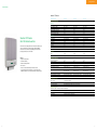
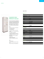
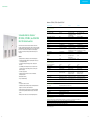
Schneider Electric
Renewable Energies
Catalog
>Solutions
>Solar inverters
>Solar inverter/chargers
>System components
Make the most of your energy
For more information visit our website at: www.schneider-electric.co.in
Schneider Electric India Pvt. Ltd. (A 100% subsidiary of Schneider Electric Industries SAS)
Corporate office : 9th Floor, DLF Building No.10, Tower C, DLF Cyber City, Phase II,
Gurgaon - 122002, Haryana, Tel: 0124 3940400, Fax: 0124 4222036
Customer Care Centre : Toll-free numbers: 1800 180 1707, 1800 103 0011,
General number: 0124 4222040, Email: [email protected]
Contents
About Schneider Electric2-3
Off-grid and backup15
Quality Policy4
Basic off-grid system
16-17
Solar inverter/chargers
String inverters
5
Solar inverters (single-phase)
•Xantrex GT Series
6-7
•Xantrex TR Series
18-19
•Xantrex XW Series 20-21
Solar charge controllers
•Xantrex XW MPPT 60 150
22-23
Central inverters8
•Xantrex XW MPPT 80 600
24-25
Solar inverters (three-phase)
•Xantrex C12 PWM
26-27
•Xantrex C Series
28-29
•Xantrex GT30 E
• Xantrex GT100 E
9-10
11-12
•Xantrex GT250 E, GT500 E
and GT630 E
13-14
Solar solution components and PV protection30
• Xantrex Gateway
31-32
•Components
33-34
•Protection
35-36
Glossary of terms
All products shown in this catalog may not be exactly as shown.
37
> About Schneider Electric
Renewable Energies
The history of Schneider Electric
Schneider Electric, founded in 1836, has transformed
itself into the global specialist in energy management.
From its roots in the iron and steel industry, heavy
machinery, and ship building, it moved into electricity
and automation management. In the late 20th
century the Schneider Group shifted its focus to the
electrical industry by separating from its non-strategic
activities and was solidified through its acquisitions of
Telemecanique in 1988, Square D in 1991 and Merlin
Gerin in 1992. In 1999 development of installation,
systems and control was bolstered with the acquisition
of Lexel, Europe’s number two in electrical distribution.
In May of the same year, the company was renamed
Schneider Electric to more clearly emphasize its
expertise in the electrical field.
2
From 2000 through 2009 Schneider Electric entered
into a phase of organic growth and began positioning
itself in new market segments: UPS (uninterruptible
power supply), movement control, building automation
and security and renewable energy through the
acquisitions of APC, Clipsal, TAC, Pelco, Xantrex
Technology and more.
As a global specialist in energy management with
operations in more than 100 countries, Schneider
Electric offers integrated solutions across multiple
market segments, including leadership positions
in energy and infrastructure, industrial processes,
building automation, data centers/networks, as
well as a broad presence in residential applications.
Focused on making energy safe, reliable, efficient,
productive and green, the company's 110,000 plus
employees achieved sales of 19.6 billion Euros in 2010,
through an active commitment to help individuals and
organizations "Make the most of their energy™."
In October of 2008, with Schneider Electric’s purchase
of Xantrex Technology, a significant milestone
was reached in the company’s expansion into the
renewable energies sector. Combining Xantrex’s
knowledge and expertise in renewable energies and
Schneider Electric’s depth of experience in energy
management was critical for the future success of the
organization in this space. The renewable energies
business of Schneider Electric is focused on designing
and developing renewable energy products and
solutions and providing best-in-class, global customer
service and technical support.
Schneider Electric provides the full solution from
the panel DC output to the grid connection, including
monitoring & supervision.
>
For more information
about Schneider Electric
and renewable energy
solutions, please visit
www.schneider-electric.com/
renewable-energies
Make the most of your energy
3
> Quality policy
At Schneider Electric’s
Renewable Energies Business,
String inverters
customer
satisfaction
is everyone's number one priority
•Providing outstanding solutions, products and services.
We are committed to
bringing a differentiated
and superior experience
to our customers
•Addressing customer issues professionally.
•Ensuring a consistent experience worldwide.
•Complying with the requirements.
•Giving precedence to customer satisfaction over any other priority.
•Listening with humbleness and acting on our customers' feedback.
We develop an exemplary
customer-centric culture
•Delivering on our commitments.
•Communicating proactively and transparently.
•Our managers lead by example.
We empower and train
our people to make no
compromise on quality
•Our people enjoy autonomy and develop accountability.
•We plan, control and relentlessly improve with our business process excellence tools and methodologies.
•We recognize and share best practices and attitudes.
The ultimate measure of quality
is customer satisfaction
4
String inverters
> Solar inverters
Xantrex™ GT Series
Device short name
GT2.8 SP
GT3.8 SP
GT5.0 SP
Photovoltaic power 3.07 kW
4.18 kW
5.3 kW
Input voltage range, MPPT 195 to 550 V
195 to 550 V
240 to 550 V
Number of MPPT
1
1
1
Max. input voltage, open circuit 600 V
600 V
600 V
Electrical specifications
Input (DC)
Max. input current
15.7 A
21.3 A
24 A
Max. input short circuit current 24 A
24 A
24 A
Nominal output power
2.5 kW
3.3 kW
5.0 kW
Output voltage 230 V, single phase
230 V, single phase
230 V, single phase
Frequency
50 Hz
50 Hz
50 Hz
Output current 14.5 A
19 A
23 A
Output (AC)
Xantrex GT Series
Grid Tie Solar Inverters
™
The Xantrex GT Series high performance PV string inverter offers high efficiency, lower installed cost, improved aesthetics and high reliability.
The Xantrex GT Series Inverter is a high quality product that offers the
best price/performance ratio on the market.
Features
• Superior PV energy harvest
• Peak inverter efficiency
Overcurrent protection 20 A 20 A
30 A
Power factor >0.9
>0.9
>0.9
Harmonic distortion
< 3%
< 3%
< 3%
Topology
Transformer, isolated
Transformer, isolated
Transformer, isolated
Peak
95.0%
95.3%
96.0%
European
94.0%
94.5%
95.2%
Power consumption, night time <1W
<1W
<1W
IP degree of protection IP54
IP54
IP54
Efficiency
General specifications
• Excellent thermal performance
Product weight 19.5 kg (42.99 lb)
20.0 kg (44.09 lb)
22.3 kg (49.16 lb)
• IP54 enclosure
Shipping weight
26 kg (57.2 lb)
26 kg (57.2 lb)
28.5 kg (62.7 lb)
• Inverters can be mounted side by side with zero clearance
Product dimensions (H x W x D) 59.7 x 40.3 x 13.6 cm
(23.5 x 15.87 x 5.35 in)
59.7 x 40.3 x 13.6 cm
(23.5 x 15.87 x 5.35 in)
59.7 x 40.3 x 13.6 cm
(23.5 x 15.87 x 5.35 in)
Shipping dimensions (H x W x D) 72 x 57 x 25 cm
(28.3 x 22.4 x 9.8 in)
71 x 58 x 24 cm
(28 x 22.8 x 9.4 in)
72 x 56 x 25 cm
(28.3 x 22 x 9.8 in)
Device mounting Wall mount (mounting bracket included)
Ambient air temperature for operation -25ºC to 65ºC (-13ºF to 149ºF)
-25ºC to 65ºC (-13ºF to 149ºF)
-25ºC to 65ºC (-13ºF to 149ºF)
Part number
864-0105 864-0104 864-1029-01
• LCD provides instantaneous information – power level, daily energy
and lifetime production, system status, and installer customized screens
Features and options
Type of cooling
Convection, fan not required
Display type LCD, 2 lines 16 digits
Communication interface Integrated RS232 and two Xanbus™ RJ45 communication ports
Regulatory approvals
CE marked according to the following EU directives and standards:
EMC Directive
EN 61000-3-2, EN 61000-3-3, EN 61000-6-1, EN 61000-6-3
Low Voltage Directive
EN 50178 and EN 60529
Other approvals Royal Decree RD 661-2007, RD 1663/2000
Specifications subject to change without notice.
6
7
Central inverters
Central inverters
> Solar inverters
Xantrex™ GT30 E
Electrical specifications
Input (DC)
Schneider Electric Xantrex
GT30 E Grid Tie Solar Inverter
™
The three-phase Xantrex GT30 E Grid Tie Solar Inverter is a 30 kW highperformance inverter that makes utility-interactive installations easier and
more cost effective. It offers superior PV energy harvest, easy installation,
high reliability and a compact, ultra-lightweight design.
Features
• One of the highest efficiencies in the 30 kW class
• Rapid MPPT
Photovoltaic power 35 kW
Input voltage range, MPPT 450 to 800 V
Max. input voltage, open circuit 840 V
Max. input current
77.4 A
Output (AC)
Nominal output power
29.9 kW
Output voltage 400 V, three phase
Frequency 50/60 Hz
Nominal output current
43.2 A
Power factor > 0.99 above 20% rated power
Harmonic distortion < 4% at rated power
Topology Integral high frequency transformer
Efficiency
Maximum
95.0% incl. transformer
European 94.2% incl. transformer
• Lightweight and easy to install
General specifications
• Multiple inverters are easily paralleled for large PV power plants
Power consumption, night time <1W
IP degree of protection IP20
Enclosure material Powder-coated aluminum
Product weight 80 kg (176.37 lb)
Product dimensions (H x W x D) 71 x 47.5 x 34.7 cm (27.95 x 18.70 x 13.66 in)
Device mounting Prepared for wall mounting
Ambient air temperature for operation 0ºC to 50ºC (32ºF to 122ºF)
Operating altitude
Up to 1500 m (4921 ft) without de-rating
Relative humidity 0 to 95%, non-condensing
Part number
1-152632-01
• Manufactured in Germany
Features and options
Type of cooling Temperature-dependent forced convection cooling
Display type
LCD, 4 lines with keypad
Protective functions AC over / under-voltage, AC over / under-frequency, over-temperature, AC and DC over-current,
DC over-voltage and reverse polarity protection
Ground fault protection DC isolation monitoring
Disconnect AC contactor integral to inverter assembly
Output relays Four relay contacts (three user-settable)
Communication interface
RS232/485, optional telephone modem for remote system monitoring
Regulatory approvals
Labeled with CE mark and complies with applicable European Directives:
EMC Directive
EN61000-6-1, -2, -3, -4, EN61000-3-12
Low Voltage Directive EN50178
The GT30 E complies with the requirements of VDEW and the Royal Decree, Spain
Specifications are subject to change without notice.
9
10
Central inverters
> Solar inverters
Xantrex™ GT100 E
Electrical specifications
Input (DC)
Schneider Electric Xantrex
GT100 E Grid Tie Solar Inverter
™
The Xantrex GT100 E Grid Tie Inverter is based on a reliable platform that
is used in grid-connect photovoltaic and wind turbine applications in North
America and Europe. Easy to install and operate, the GT100 E automates
start up and shut down. It incorporates advanced Maximum Power Point
Tracking Technology (MPPT) to maximize the energy harvested from a
PV array. To minimize power losses during the conversion process, the
inverter’s switching technology uses insulated gate bi-polar transistors.
Features
Photovoltaic power 112 kW
Input voltage range, MPPT 300 to 650 V
Max. input voltage, open circuit 650 V
Max. input current 347 A
Output (AC)
Nominal output power 100 kW
Output voltage 400 V, three phase
Frequency 50 Hz, optional 60 Hz
Nominal output current 144 A
Power factor > 0.99 above 20% rated power
Harmonic distortion < 3% at rated power
Topology Integral isolation transformer
Efficiency
Peak 96.6% incl. transformer
European
96.0% incl. transformer
General specifications
• Digital Signal Processor (DSP) based controls with self-diagnostics
and LCD for display of operating status
Power consumption, night time
93 W
IP degree of protection
IP21
• Inverter shut off and disconnects
Enclosure material
Steel
• Over- and under-voltage and frequency protection, shutting down
the inverter
Product weight
870 kg (1918 lb)
Product dimensions (H x W x D) 190.5 x 120.5 x 60.6 cm (75 x 47.44 x 23.86 in)
• Anti-islanding protection - prevents back-feeding inverter-generated power to the grid in the event of a utility outage
Ambient air temperature for operation
-10ºC to 45ºC (14ºF to 113ºF)
Operating altitude
Up to 2000 m (6562 ft) without de-rating
• User definable power tracking allows the user to match the inverter
to the array, as well as to adjust delay periods to customize system shutdown sequences
Relative humidity
0 to 95% non-condensing
Part number
1-153417-02
• Graphical user interface software for real time communications, monitoring, and control
• Isolated design with integrated transformer
• Multiple inverters can be paralleled for large power installations
Options
• Insulation monitoring system
• Remote monitoring and fault notification via various communication options
• Warranty extensions and service contracts with uptime guarantees
Features and options
Type of cooling Forced convection cooling
Display type Four-line, 80-character VFD with a keypad
Protective functions AC over / under-voltage, AC over / under-frequency, over-temperature, AC and DC over-current, DC over-voltage
AC/DC disconnect
Integral to inverter assembly
Communication interface
Modems (Ethernet or Wireless) for remote monitoring and faults notification
Regulatory approvals
The GT100 E is compliant to applicable European directives and CE marked:
EMC Directive
EN61000-6-2, EN61000-6-4
The GT100 E complies with the requirements of Spain's RD1663 and RD661
Specifications are subject to change without notice.
11
12
Central inverters
> Solar inverters
Xantrex™ GT250 E, GT500 E, and GT630 E
Device short name
GT250 E
GT500 E
GT630 E
Photovoltaic power 280 kW
560 kW
705 kW
Input voltage range, MPPT 450 to 800 V
450 to 880 V (495 to 880 V for grid interactive option, reduced
current above 820 V)
575 to 880 V (reduced current
above 820 V)
Electrical specifications
Input (DC)
Schneider Electric Xantrex™
GT250 E, GT500 E, and GT630 E
Grid Tie Solar Inverters
The Xantrex GT250 E, GT500 E and GT630 E Grid Tie Solar Inverters
provide a competitive price and performance ratio, and feature the insulated
gate bipolar transistor (IGBT) switching technology to reach a high efficiency
level of 98.4%. These inverters can handle the most demanding grid
interactive features while continuing to deliver maximum active power
to the grid.
Max. input voltage, open circuit 880 V 930 V (1000 V optional)
930 V (1000 V optional)
Max. input current 555 A 1120 A
1120 A
Nominal output power
250 kW 500 kW
630 kW
Output voltage 315 V three phase 315 V three phase
375 V three phase
Frequency 50 Hz, optional 60 Hz 50 Hz, optional 60 Hz 50 Hz, optional 60 Hz
Nominal output current 460 A
1040 A
1040 A
Output (AC)
Power factor > 0.99 above 20% rated power > 0.99 above 20% rated power > 0.99 above 20% rated power
(optional 0.93 leading to 0.93
(optional 0.93 leading to 0.93
lagging with grid interactive feature) lagging with grid interactive feature)
Harmonic distortion < 3% at rated power < 3% at rated power
< 3% at rated power
Efficiency
Features
Maximum 97.5%
98.1% (98.3% for grid
interactive option)
98.4%
• Digital Signal Processor (DSP) based controls with self-diagnostics
European 96.6% 97.6% (97.9% for grid interactive
interactive option)
98.2%
Power consumption, night time < 100 W < 100 W
< 100 W
IP degree of protection IP20 IP20 IP20
• LCD display with keypad for display of operating status and for access
of user-changeable settings
• Over and under-voltage and frequency protection, shutting down
the inverter
• User definable power tracking allows the user to match the inverter
to the array, as well as to adjust delay periods to customize system shutdown sequences
• DC and AC surge protection
• Graphical user interface software for real time communications,
monitoring and control
• Manufactured in Germany
• Five-year standard warranty
Options
General specifications
Enclosure material Steel
Steel
Steel
Product weight 1160 kg (2557.36 lb)
1770 kg (3902.18 lb)
(without 1000 V option)
1770 kg (3902.18 lb)
(without 1000 V option)
Product dimensions (H x W x D) 211.2 x 200.6 x 60.5 cm (83.15 x 78.98 x 23.82 in)
211.2 x 240.6 x 60.5 cm
(83.15 x 94.72 x 23.82 in)
(without 1000 V option)
211.2 x 240.6 x 60.5 cm
(83.15 x 94.72 x 23.82 in)
(without 1000 V option)
Ambient air temperature for operation -10ºC to 45ºC (14ºF to 113ºF) -10ºC to 45ºC (14ºF to 113ºF)
-10ºC to 45ºC (14ºF to 113ºF)
Operating altitude Full power up to 1500 m (4921 ft), with power derating above 1500 m
Full power up to 1500 m (4921 ft), with power derating above 1500 m
Full power up to 1500 m (4921 ft)
with power derating above 1500 m
Relative humidity 0 to 95% non-condensing 0 to 95% non-condensing
0 to 95% non-condensing
Part number
820-0029-02-01*
822-5005-00-00*
822-6305-00-00*
• 1000 V Input for GT500 E / GT630 E
Features and options
• Grid interactive features including low voltage ride through and reactive (VAR) power control for the GT500 E and GT630 E
Type of cooling Temperature-dependent forced convection cooling
Display type LCD, 4 lines 20 digits with keypad
• Insulation monitoring systems and positive or negative grounding kits
Protective functions AC over / under-voltage, AC over / under-frequency, over-temperature, AC and DC over-current, DC over-voltage
• Remote monitoring and faults notification via various communication options
AC/DC disconnect
Integral to inverter assembly
Combiner boxes
Optional feature (information on request)
Container solution
Optional feature (information on request)
Warranty
Five-year standard
• Warranty extensions and service contracts with uptime guarantees
Regulatory approvals
GT250 E, GT500 E and GT630 E are CE marked for the EMC Directive (EN61000-6-2 and EN61000-6-4) and Low Voltage Directive (EN50178)
GT500 E and GT630 E with grid-interactive options comply with German (EON, BDEW) and French (EDF) requirements
GT500 E complies with Spain's RD1663 and RD661
GT250 E, GT500 E and GT630 E comply with the requirements of Italy's ENEL DK5940
Specifications are subject to change without notice.
* Other options available upon request.
13
14
Off-grid and backup
17
Off-grid and backup
Basic off-grid system
With an off-grid system, you can easily produce your own power without the expense
and environmental impact of extending power lines, or relying completely on a generator.
A basic off-grid system consists of a renewable energy source which generates DC
power, a battery bank that stores the DC power, and an inverter. Our inverter is the
intelligent center of a renewable power system, seamlessly converting DC power to
clean AC electricity for your needs.
With a backup system, grid-connected homes can benefit from electricity even if there
is a grid failure. An inverter/charger automatically detects the failure and switches to
backup power using energy stored in a battery bank.
XW System
TR Series
XW System
TR Series
16
Residential
off-grid system
Residential
backup system
17
Off-grid and backup
> Solar inverter / chargers
Xantrex™ TR Series (230 V / 50 Hz)
Device short name
TR1512 230 50
TR1524 230 50
TR2424 230 50
Continuous output power
1.5 kVA
1.5 kVA
2.4 kVA
Output voltage 230 V
230 V
230 V
Electrical specifications
Schneider Electric Xantrex
TR Series Inverter/Chargers
(230 V / 50 Hz)
™
The Xantrex TR Series Inverter/Charger is an economical power conversion
solution available in a wide range of modified sine-wave output voltages
and power levels. The Xantrex TR is an excellent choice for off-grid
applications, or to deliver dependable backup power to essential circuits in
a home or business during a power outage.
Features
• 1500 VA and 2400 VA models
• 230 V / 50 Hz models
• 12 Vdc and 24 Vdc models
• New digital display shows kilowatts (kW) when inverting and amps (A) when charging, plus incorporates a robust ON/OFF membrane switch
and status indicators
• New power factor corrected (PFC) charging, combined with a more sophisticated multi-stage battery charging algorithm, reduces current draw and generator run-time
Frequency 50 Hz
50 Hz
50 Hz
Output current
6.4 A
6.4 A
10.4 A
Surge capability max. output & duration:
Overload 10 sec rating
Short circuit 10 sec rating
3000 VA
26.5±2.5 Apk
3000 VA
26.5±2.5 Apk
4800 VA
42±4 Apk
Adjustable load sensing range
10 W minimum to 480 W maximum
10 W minimum to 480 W maximum
10 W minimum to 480 W maximum
Type of signal (invert mode)
Modified sine wave
Modified sine wave
Modified sine wave
DC input current at no load
(search mode)
0.35 A 0.20 A 0.20 A
DC input voltage limits
11 to 15 V 22 to 30 V
22 to 30 V
Rated DC input current
158 A
77 A
121 A
Load power factor (allowed)
0.8 to 1.0 (leading or lagging)
0.8 to 1.0 (leading or lagging)
0.8 to 1.0 (leading or lagging)
Series operation
No
No
No
AC input voltage limits
(bypass/charge mode)
120 to 253 V (wide), 180 to 253 V (narrow), 120 to 253 V (wide)
180 to 253 V (narrow)
120 to 253 V (wide)
180 to 253 V (narrow)
Input frequency
45 to 55 Hz (narrow-charge & pass-through)
45 to 68 Hz (wide-charge)
41 to 68 Hz (wide pass-through)
Built-In internal
supplemental breakers
15 A bypass, 8 A charger
15 A bypass, 8 A charger
Charging current (adjustable)
10 to 70 A
5 to 35 A
10 to 70 A
AC input current at max. charge rate
5.9 A
6.0 A
10.4 A
0.83
0.92
15 A bypass,
15 A charger
Charger power factor
0.91
Multi-stage charging Yes – bulk, absorption and float, plus user-initiated equalize (for flooded batteries only)
Temperature compensation
Battery temperature sensor included Battery temperature sensor included Battery temperature sensor included
Automatic transfer relay 15 A
15 A
15 A
Transfer time (typical)
< 40 ms (wide), < 20 ms (narrow)
< 40 ms (wide), < 20 ms (narrow)
< 40 ms (wide), < 20 ms (narrow)
> 92%
> 91%
> 94%
Product weight
19 kg (42 lb)
19 kg (42 lb)
19 kg (42 lb)
Shipping weight
23.6 kg (52 lb)
23.6 kg (52 lb)
23.6 kg (52 lb)
• Durable powder coated, corrosion resistant steel chassis
Product dimensions (H x W x D) 18.4 x 21.6 x 54.6 cm
(7.2 x 8.5 x 21.5 in)
18.4 x 21.6 x 54.6 cm
(7.2 x 8.5 x 21.5 in)
18.4 x 21.6 x 54.6 cm
(7.2 x 8.5 x 21.5 in)
• Two-year standard warranty
Shipping dimensions (H x W x D)
30 x 31.5 x 67.5 cm
(11.8 x 12.4 x 26.6 in)
30 x 31.5 x 67.5 cm
(11.8 x 12.4 x 26.6 in)
30 x 31.5 x 67.5 cm
(11.8 x 12.4 x 26.6 in)
Device mounting Wall mount (with 16 in mounting centers) Wall mount (with 16 in mounting centers) Wall mount (with 16 in mounting centers)
Ambient air temperature for operation
0°C to 50°C
(32°F to 122°F)
• Simplified controls with a snap-on cover that protects settings from being accidentally changed
• Improved thermal performance allows full output power to 50°C without de-rating
• High surge capacity starts difficult loads and handles overload conditions
• Circuit boards are conformally-coated to protect them from corrosion
for longer life and improved reliability
Components
• TR-Remote On/Off Switch – includes LED status indicator
• TR-Conduit Box – connects to the DC side of the inverter and accepts
2 cm, 2.5 cm or 5 cm conduit
Efficiency
Peak
General specifications
0°C to 50°C
(32°F to 122°F)
0°C to 50°C
(32°F to 122°F)
Warranty
Two-year standard
Two-year standard
Two-year standard
Part number
989-1025
989-1030
989-1035
Optional components
Xantrex TR Conduit Box (989-1050)
Connects to the DC side of the inverter and accepts 3/4, 1 or 2 inches conduit
Xantrex TR Remote On/Off Switch (989-1060)
Includes LED status indicator
Regulatory approvals
CE Marked and compliant with Europe's EMC Directive (EN61000-6-1, -6-3, -3-2, and -3-3) and Low Voltage Directive (EN50178)
Specifications are subject to change without notice.
18
19
Off-grid and backup
> Solar inverter / chargers
Xantrex™ XW Series (230 V / 50 Hz)
Device short name
XW6048 230 50
XW4548 230 50
XW4024 230 50
6.0 kVA
12.0 kVA (15 sec)
26.1 A
53 A
131 A
True sine wave
56 A
8 ms
50.4 V 44 to 64 V
100 A
0.98
0 to 12 V, maximum 250 mA DC
< 7 W
230 V +/- 3%
165 to 280 V (230 V nominal)
50 Hz +/- 0.1 Hz
40 to 68 Hz (50 Hz nominal)
< 5% at rated power
AC1 (Grid), AC2 (Generator)
60 A single-pole
Disabled
4.5 kVA
9.0 kVA (20 sec)
19.6 A
40 A
96 A
True sine wave
56 A
8 ms
50.4 V 44 to 64 V
85 A
0.98
0 to 12 V, maximum 250 mA DC
< 7 W
230 V +/- 3%
165 to 280 V (230 V nominal)
50 Hz +/- 0.1 Hz
40 to 68 Hz (50 Hz nominal)
< 5% at rated power
AC1 (Grid), AC2 (Generator)
60 A single-pole
Disabled
4.0 kVA
8.0 kVA (20 sec)
17.4 A
35 A
178 A
True sine wave
56 A
8 ms
25.2 V
22 to 32 V
150 A
0.98
0 to 12 V, maximum 250 mA DC
<7W
230 V +/- 3%
165 to 280 V (230 V nominal)
50 Hz +/- 0.1 Hz
40 to 68 Hz (50 Hz nominal)
< 5% at rated power
AC1 (Grid), AC2 (Generator)
60 A single-pole
Disabled
95.4%
95.6%
94.0%
Electrical specifications
Schneider Electric Xantrex™
XW Inverter/Charger
The Schneider Electric Xantrex XW inverter/charger features sine-wave power
and advanced battery charging technology. The product line offers inverter/chargers
in power levels from 4 kW to 6 kW in an expandable configuration allowing for
future system growth in either single or three-phase applications up to 36 kW.
The products can be used in either a grid-tied with battery backup or off-grid application to suit a wide variety of installations.
Features
• True sine-wave output
• 230 V / 50 Hz Models
Continuous power
Surge rating Output current
Peak output current
Input current at rated power
Type of signal
Automatic transfer relay
Typical transfer time DC input voltage (nominal) Input voltage limits Charging current Power factor corrected charging
Auxiliary relay output Power consumption (search mode) AC input voltage (nominal)
Input voltage limits (bypass/charge mode)
Frequency
AC input frequency range (bypass/charge mode)
Total harmonic distortion (THD)
AC connections
AC input breaker
Utility interactive
Efficiency
Peak
• 24 V models rated at 4000 VA and 48 V models rated at 4500 VA or 6000 VA
General specifications
• High surge capacity – Full 200% rated output power is delivered to loads
IP degree of protection
Product weight
Shipping weight
Product dimensions (H x W x D)
Shipping dimensions (H x W x D)
IP20 (sensitive electric components sealed inside enclosure)
55.2 kg (121.7 lb)
53.5 kg (118 lb)
76.7 kg (169 lb)
75 kg (165 lb)
58 x 41 x 23 cm (23 x 16 x 9 in)
58 x 41 x 23 cm (23 x 16 x 9 in)
71.1 x 57.2 x 39.4 cm 71.1 x 57.2 x 39.4 cm
(27.99 x 22.52 x 15.51 in)
(27.99 x 22.52 x 15.51 in)
Device mounting
Ambient air temperature for operation
Wall mount (backplate included)
Wall mount (backplate included)
-25°C to 70°C (-13°F to 158°F) (power derated above 45°C (113°F))
Wall mount (backplate included)
Communication network type
Xanbus™
Part number
865-1035
Xanbus™
865-1045
• All models suitable for off-grid or hybrid/backup power applications
• Single-phase (230 V / 50 Hz) and three-phase (230/400 V / 50 Hz) configurations possible
• Up to four inverters can be installed in parallel to create larger single-phase
systems up to 24 kVA
• Up to two inverters per phase can be connected for three-phase installations
up to 36 kVA
• Dual AC inputs (grid and generator) with automatic transfer; external transfer
switch not required
• Efficient, power factor corrected, high-current, multistage battery charging
Features and options
Display type
• Configurable auxiliary output
• Non volatile memory stores parameter settings
• Full control of generator with optional automatic generator start (AGS)
• CE marked
• Mounting bracket included
• Local LED display on inverter shows output power, charge current and battery
level, to provide system status at-a-glance
• Xanbus™ Network provides plug-and-play networking
Xanbus™
865-1040 52.5 kg (116 lb)
74 kg (163 lb)
58 x 41 x 23 cm (23 x 16 x 9 in)
71.1 x 57.2 x 39.4 cm
(27.99 x 22.52 x 15.51 in)
Supported battery types
Battery bank size
Battery temperature sensor
Non volatile memory
Multiple unit configurations
tatus LEDs indicate AC In status, faults/warnings, equalize mode, On/Off and equalize button battery level.
S
Three-character display indicates output power or charge current
Flooded (default), Gel, AGM, custom Flooded (default), Gel, AGM, custom Flooded (default), Gel, AGM, custom
100 to 2000 Ah (scaled to PV array size)
Included
Included
Included
Yes
Yes
Yes
Single-phase: up to four parallel units. Three-phase: two units per phase
Optional components (see page 72 for more details)
Xantrex XW Remote display (865-1050)
XW SCP monitors and configures all devices connected to Xanbus Network
Xantrex XW Generator support (865-1060)
XW AGS module connects to Xanbus Network. Automatically activates generator to recharge depleted battery bank
or assist inverter with heavy loads
Xantrex XW Conduit Box (865-1025)
XW CB encloses the bottom of the inverter and protects the cabling. Provides knockouts for 2 cm, 2.5 cm, 3.2 cm,
6 cm, and 6.5 cm conduit
Xantrex XW MPPT 60 150 (865-1030-1) (page 60) XW MPPT Solar Charge Controller with MPPT delivers the maximum energy available from the PV array
Xantrex XW MPPT 80 600 (865-1032) (page 62)
to the battery bank
Xantrex XW Configuration Tool (865-1155)
Xantrex XW Configuration Tool aids dealers and installers by simplifying and expediting the configuration
and/or troubleshooting of a Xantrex XW System
Regulatory approval
CE marked according to the following EU directives and standards:
EMC Directive
EN61000-6-1, EN61000-6-3, EN61000-3-2, EN61000-3-3
Low Voltage Directive
EN50178
Specifications are subject to change without notice.
20
21
Off-grid and backup
> Solar charge controllers
Xantrex™ XW MPPT 60 150
Device short name
XW MPPT 60 150
Electrical specifications
Schneider Electric Xantrex
XW MPPT 60 150 Solar Charge
Controller
™
12, 24, 36, 48, 60 V
Max. PV array voltage (operating) 140 V
Max. PV array open circuit voltage 150 V including temperature correction factor
Max. array short-circuit current 60 A (48 A @ STC)
Max. charge current
60 A
Max. and min. wire size in conduit #6 AWG to #14 AWG (10 to 2.5 mm²)
Charger regulation method
Three-stage (bulk, absorption, float) plus manual equalization
Two-stage (bulk, absorption) plus manual equalization
General specifications
The Xantrex XW MPPT 60 150 is a photovoltaic (PV) charge controller
that tracks the maximum power point of a PV array to deliver the
maximum available current for charging batteries. When charging,
the Xantrex XW MPPT 60 150 regulates battery voltage and output
current based on the amount of energy available from the PV array
and state-of-charge of the battery.
Power consumption, night time 2.5 W
Enclosure material
Indoor, ventilated, sheet metal chassis with 2.2 cm and 2.8 cm (7/8 in and 1 in) knockouts and aluminium heat-sink
Product weight
4.8 kg (10.75 lb)
Shipping weight 8 kg (17.6 lb)
Product dimensions (H x W x D) 36.8 x 14.6 x 13.8 cm (14.5 × 5.75 × 5.5 in)
Shipping dimensions (H x W x D)
48.3 x 22.9 x 35 cm (19 × 9 × 9.75 in)
Device mounting Vertical wall mount
Ambient air temperature for operation (full power) -20°C to 45°C (-4°F to 113°F)
Features
• Can be used with 12, 24, 36, 48, and 60 V battery systems and is
able to charge a lower nominal voltage battery from a higher nominal voltage array
• Maximum Power Point Tracking (MPPT) algorithm continually seeks
the maximum power available from the PV array
Storage temperature range
-40°C to 85°C (-40°F to 185°F)
Operating altitude
Sea level to 2000 m (6562 ft)
Warranty
Five-year standard
Part number
865-1030-1
Features and options
Display type
• Integrated PV ground fault protection for negative grounded arrays
• Convection-cooled design does not require a cooling fan − large, aluminum, die-cast heat-sink allows full output current up to 45°C
without thermal derating
Nominal battery voltage • Selectable two or three-stage charging algorithms with manual equalization to maximize system performance and improve battery life
LCD, 2 lines 16 digits
Regulatory approvals
Safety
CSA Certified (UL1741 rev. 2005, CSA 107.1) and CE Marked for the Low Voltage Directive (EN50178)
EMC
FCC and Industry Canada (Class B) and CE Marked for the EMC Directive (EN61000-6-1, -6-3)
Specifications are subject to change without notice.
• Configurable auxiliary output
• 2 lines 16 digit LCD and four buttons
for configuration and system monitoring
• Input over-voltage and under-voltage protection, output over-current protection, and backfeed (reverse current) protection (warning and fault messages appear on LCD when unit shuts down as a protective measure)
• Can also be used with other battery-based solar energy systems
• Over-temperature protection and power derating when output power
and ambient temperature are high
• Battery Temperature Sensor (BTS) included − automatically provides
temperature compensated battery charging
• Xanbus™-enabled network communications protocol
• Five-year standard warranty
22
23
Off-grid and backup
> Solar charge controllers
Xantrex™ XW MPPT 80 600
Device short name
XW MPPT 80 600
Electrical specifications
Schneider Electric Xantrex
XW MPPT 80 600 Solar Charge
Controller
™
Nominal battery voltage 24 and 48 V (Default is 48 V)
Max. PV array voltage (operating) 195 to 550 V
Max. PV array open circuit voltage 600 V including temperature correction factor
Array short-circuit current 35 A (28 A @ STC)
Max. charge current
80 A
Max. and min. wire size in conduit #6 AWG to #14 AWG (13.5 to 2.5 mm2)
Charger regulation method: Three-stage (bulk, absorption, float) plus manual equalization
Two-stage (bulk, absorption) plus manual equalization
General specifications
Power consumption, night time <1W
Enclosure material
Indoor, ventilated, aluminum sheet metal chassis with 22.22 mm and 27.76 mm (7/8 in and 1 in) knockouts
and aluminum heat sink
Product weight 13.5 kg (29.8 lb)
Shipping weight
17.4 kg (38.3 lb)
Product dimensions (H x W x D)
76 × 22 × 22 cm (30 × 8.625 × 8.625 in)
Shipping dimensions (H x W x D) 87 × 33 × 27 cm (34.3 × 13 × 10.6 in)
Device mounting Vertical wall mount
Ambient air temperature for operation -20°C to 65°C (-4°F to 149°F), power derating above 45°C
Storage temperature range
-40°C to 85°C (-40°F to 185°F)
Operating altitude
Sea level to 2000 m (6562 ft)
Warranty
Five-year standard
• Accepts array voltages up to 600V, increasing installation flexibility
and reducing installation cost
Part number 865-1032
• MPPT to improve energy harvest over a wide range of environmental conditions
Regulatory approvals
The XW MPPT 80 600 is an innovative solar charge controller that offers
an industry-first set of features: high PV input voltage (up to 600 Vdc),
Maximum Power Point Tracking (MPPT), and 80 A charge current. 600 Vdc
PV input voltage delivers lower installation costs through fewer PV strings,
longer home runs, smaller wiring and conduit, and virtual elimination of
PV combiner boxes and circuit breakers. MPPT technology helps harvest
the most energy available from the PV array, regardless of environmental
conditions. 80 A battery charge current allows for connection of arrays
rated at up to 4800 W (48 V battery bank).
Features
• 80 A charge current from large PV arrays with just two strings
Certified to UL1741: 2nd Ed and to CSA 107.1-01
Specifications are subject to change without notice.
• Charges 24 V or 48 V battery banks
• Full output power at 45ºC without derating (2560 W for 24 V systems, 4800 W for 48 V systems)
• Configurable for positive, negative, and ungrounded PV systems
• Integrated PV ground fault protection
• Configurable Auxiliary output
• Input over-voltage and under-voltage protection, output over current protection, and backfeed (reverse current) protection
• Over-temperature protection and power derating when ambient temperatures are high
• Battery Temperature Sensor (BTS) included – automatically provides temperature compensated battery charging
Schneider Electric Xantrex XW SCP
• Xanbus™–enabled network communications protocol allows settings and activity to be communicated to other Xanbus-enabled devices, such as the XW Hybrid Inverter/Charger, the XW System Control Panel (SCP), XW Automatic Generator Start (XW AGS) and other XW Solar Charge Controllers
• Provides on-board Xanbus™ network power for use in stand-alone applications with communications gateway
• Can be installed in a stand-alone mode with XW System Control Panel (XW SCP) (sold separately)
• Five-year standard warranty
24
25
Off-grid and backup
> Solar charge controllers
Xantrex™ C12 PWM
Device short name
C12 PWM
Electrical specifications
Schneider Electric Xantrex
C12 PWM Charge Controller
™
The Xantrex C12 PWM charge, lighting, or load controller is uniquely
sophisticated. As a charge controller, it features three-stage charging,
user definable voltage parameters, and automatic equalization. Standard
in the Xantrex C12 PWM’s load control circuitry are field adjustable low
voltage disconnect and reconnect points, along with a five minute low
battery disconnect warning. The Xantrex C12 PWM also functions as a
lighting controller. Lighting run time is adjustable from two to eight hours
or can be set from dusk to dawn operation. It is used worldwide in a variety
of applications, including remote village lighting systems and automatic
outdoor lighting. An optional battery temperature sensor ensures precise
battery charging regardless of battery temperature fluctuations.
Features
• Silent, pulse width modulated microprocessor control (maximizing
battery life)
• Field adjustable voltage and battery set points
• Electronic protection against short-circuit, overload, over-temperature
and reverse polarity conditions
• Two-year standard warranty
Rated PV current
12 A at 12 V only
Max. DC load
12 A with auto reset
Min. operating voltage
6V
Max. voltage drop (PV to battery)
0.3 V
Max. voltage drop (battery to DC load)
0.5 V
Regulation setting
13 to 15 V
Equalize setting
Bulk plus 1 volt for two hours
Max. stranded wire size
#10 AWG stranded (5.2 mm2)
Typical consumption while charging
0.007 A
Typical consumption with load disconnected
0.003 A
General specifications
Power consumption, night time
0.003 A
Enclosure material
Powder coated steel with strain relief for wiring and knockouts for up to 3.5 in conduits
Product weight
0.9 kg (1.98 lb)
Shipping weight
1.13 kg (2.49 lb)
Product dimensions (H x W x D)
16.5 x 11 x 4 cm (6.5 x 4.33 x 1.57 in)
Shipping dimensions (H x W x D)
20.3 x 11.7 x 4 cm (7.99 x 4.61 x 1.57 in)
Device mounting
Vertical wall mount – indoor only
Ambient air temperature for operation
0°C to 40°C (32°F to 104°F)
Warranty
Two-year standard
Part number
C12 – charge controller
Features and options
Regulation method
Standard – three-stage (bulk, absorption, and float), solid state, pulse width modulation
Field adjustable control setpoints
Standard – removable knobs and calibrated scales
Setting protection
Standard – knobs can be removed to prevent tampering
Testpoints
Standard – provided for each setting
Automatic equalization
Standard – every 30 days or after voltage reaches low voltage disconnect – can be disabled
External battery temperature compensation
Optional – battery temperature sensor (BTS)
Short circuit protection
Standard – fully electronically protected with auto reset and manual reset switch, protects both the loads
and PV array from damage from short circuits – a fuse for the battery is still advised to protect
the battery wires if located separately
Reverse polarity protection
Standard – fully protected
Low voltage disconnect
Standard – adjustable automatic or manual operation, manual reconnection includes warning flash
of loads five minutes before and a ten minute grace period
Regulatory approvals
CE marked for the Low Voltage Directive and EMC Directive
Specifications are subject to change without notice.
26
27
Off-grid and backup
> Solar charge controllers
Xantrex™ C Series
Device short name
C35 PWM
C40 PWM
C60 PWM
Rated PV current
35 A
40 A
60 A
Charging / load current @ 25°C (77°F)
35 A
40 A
60 A
Voltage configurations
12 and 24 V
12, 24, and 48 V
12 and 24 V
Max. PV open circuit array voltage
55 V
125 V
55 V
Electrical specifications
Schneider Electric Xantrex
C Series Controller
™
The Xantrex C35 PWM and C60 PWM are field configurable for
12- and 24- V operation. The Xantrex C40 PWM may be configured
for 12-, 24-, or 48- V operation. All can be used as a charge, diversion,
or load controller and come with a standard multi-color charge status LED.
Max. voltage drop through controller
0.30 V
0.30 V
0.30 V
Total operating consumption
15 mA
15 mA
15 mA
Recommended breaker size
60 A rated at 100% continuous duty 60 A rated at 100% continuous duty 60 A rated at 100% continuous duty
Recommended wire size
#6 AWG rated at 90°C (194°F)
#6 AWG rated at 90°C (194°F)
#6 AWG rated at 90°C (194°F)
Lead acid battery settings
Adjustable
Adjustable
Adjustable
NiCd battery settings
Adjustable
Adjustable
Adjustable
Load control mode
Low voltage reconnect – adjustable (sticker provided with unit) all models
Low voltage disconnect – user selectable manual or automatic reconnection –
(includes warning flash before disconnect and provides a one time, user selected grace period) all models
Features
General specifications
• Silent, pulse width modulated microprocessor control
(helping to maximize battery life)
Power consumption, night time 3 mA
Enclosure material
Indoor, ventilated, powder coated steel Indoor, ventilated, powder coated steel Indoor, ventilated, powder coated steel
with 2 cm and 2.5 cm knockouts
with 2 cm and 2.5 cm knockouts
with 2 cm and 2.5 cm knockouts
• Field adjustable voltage and battery type set points
• Electronic protection against short-circuit, overload,
over-temperature, and reverse polarity conditions
• Two-year standard warranty
C Series
3 mA
3 mA
Product weight
1.2 kg (2.65 lb)
1.4 kg (3.09 lb)
1.4 kg (3.09 lb)
Shipping weight
1.4 kg (3.09 lb)
1.6 kg (3.53 lb)
1.6 kg (3.53 lb)
Product dimensions (H x W x D)
20.3 x 12.7 x 6.4 cm
(7.99 x 5 x 2.52 in)
25.4 x 12.7 x 6.35 cm
(10 x 5 x 2.5 in)
25.4 x 12.7 x 6.35 cm
(10 x 5 x 2.5 in)
Shipping dimensions (H x W x D)
31.5 x 17.8 x 6.4 cm
(12.4 x 7.01 x 2.52 in)
31.5 x 17.8 x 6.4 cm
(12.4 x 7.01 x 2.52 in)
31.5 x 17.8 x 6.4 cm
(12.4 x 7.01 x 2.52 in)
Device mounting
Vertical wall mount – indoor only
Vertical wall mount – indoor only
Vertical wall mount – indoor only
• CM: Cumulative amp hour meter
Ambient air temperature for operation
0°C to 40°C (32°F to 104°F)
0°C to 40°C (32°F to 104°F)
0°C to 40°C (32°F to 104°F)
• CM/R: Remote cumulative amp hour meter
(available in 50 or 100 foot lengths)
Operating altitude
4572 m (15000 ft)
4572 m (15000 ft)
4572 m (15000 ft)
Non-operating altitude
15240 m (50000 ft)
15240 m (50000 ft)
15240 m (50000 ft)
• BTS: Battery temperature sensor
Warranty
Two-year standard
Two-year standard
Two-year standard
Part number
C35, C40, C60 – charge controllers
CM – Front display panel
CM/R-50, CM/R-100 – Remote display panel
BTS – Battery temperature sensor
Optional components:
CM and CM/R Digital Meter or Remote Display
This digital meter mounts onto the front of a charge controller or as
a remote it can be installed up to 31 m away. It displays volts, amps,
and resettable cumulative amp hours for a solar array, DC loads,
or diversion loads, depending on the application. The CM/R comes
with 15 or 30.5 m communication cable for remote installation.
Features and options
Display type
CM, CM/R-50, or CM/R-100 – optional LCD – backlit, alphanumeric display showing battery voltage, DC amperage,
cumulative amp hours, and amp hours since last reset – remote includes 15 or 30.5 m (49 or 100 ft) cable
Regulation method
Solid state, three-stage (bulk, absorption, and float), pulse width modulation
Field adjustable control setpoints
Two user adjustable voltage setpoints for control of loads or charging sources –
settings retained if battery is disconnected
Equalization charge
User selectable manual or automatic equalization – every 30 days
Battery temperature sensor
BTS – optional remote battery temperature sensor for increased charging precision
Regulatory approvals
Safety
UL Listed to UL1741 and CSA 14; CE Marked for the Low Voltage Directive
EMC
FCC and Industry Canada Class B, CE Marked for the EMC Directive
Specifications are subject to change without notice.
28
29
Solar solution components
and PV protection
33
Components
Xantrex™ Gateway
Electrical specifications
Schneider Electric Xantrex
Gateway
™
Communication Physical layer 2, CAN
Communication protocol Xanbus™
Max. Xanbus cable length 40 m (131 ft)
Max. Ethernet cable length 60 m (197 ft)
Connectors 3 RJ45 – 8 pins (two Xanbus, one Ethernet)
Communication specifications
The Xantrex Gateway bridges the gap between a Xantrex GT or XW System
and the system owner’s computer, making it the central component for
a residential or small commercial remote monitoring system.
Ethernet
IEEE Std 802.3-2005™
Wireless 802.11.4b and 802.11.4g; WEP and WPA security
Channels 1-11 (US/Canada), 1-9 (Europe)
General specifications
Product weight 0.21 kg (0.46 lb)
The Xantrex Gateway logs performance data directly from the Xantrex GT
or XW System, and transmits it to the included widget-based monitoring
software for a simple and graphically rich view of system performance.
More than a data logger, the Xantrex Gateway offers a web page with the
ability to configure automated email reports and fault status to the user
or installer.
Product dimensions (H x W x D) 11.2 x 19.0 x 45 cm (4.41 x 7.48 x 17.72 in)
Height including antenna 24.9 cm (9.8 in)
Part number
865-1056
North America
EMC FCC and Industry Canada class B
The Xantrex Gateway includes both built-in Wi-Fi and Ethernet connectivity
allowing for flexible and simple set up for wireless or wired connection to
a router or direct to a PC.
Europe
Safety
EMC
Telecom
Regulatory approvals
Low Voltage Directive EN 60950-1
EMC Directive EN 55022, EN 55024
R&TTE Directive, ETSI EN 301 489-1, ETSI EN 301 489-17
Specifications are subject to change without notice.
The Xantrex Gateway logs and transmits performance
data including:
• System power production
• Inverter specific power production
• Lifetime energy production; daily, weekly, monthly energy production graphs
• Inverter faults with date and time stamp
Features
• Can monitor a network consisting of up to 20 single phase GT
inverters or up to eight Xantrex XW devices (Xantrex XW Inverter/
Charger(s), Xantrex XW MPPT Solar Charge Controller(s),
Xantrex XW SCP, and Xantrex XW AGS)
• Wi-Fi/Ethernet module with 10/100 Base-T or 802.11 b/g
• Can be configured to send energy and alarm reports via email
• Graphical interactive solar monitoring software
• Embedded web page for configuring the Xantrex Gateway and upgrading inverter firmware
• 16 megabytes of storage
31
32
Components
Schneider Electric XantrexTM XW System components
Photovoltaic installations components
Schneider Electric Xantrex™ XW SCP*
Schneider Electric Solar Disconnect Switch
(865-1050)
(REHU393IP (3 Poles, 100 Amps), REHU493IP (4 Poles, 100 Amps), REHU394IP (3 Poles, 200 Amps), REHU494IP (4 Poles, 200 Amps))
The Xantrex XW System Control Panel features a graphical, backlit LCD display that provides system configuration
and diagnostic information for devices connected to the Xanbus™-enabled network. The XW SCP gives a single
point of control to setup and monitor an entire system, which may consist of multiple Xantrex XW Inverter/Chargers,
Xantrex XW MPPT Solar Charge Controllers and other components.
The 1000 VDC disconnect switch functions as a local disconnect for a string of PV panels and is IEC 60947 compliant for
use in Photovoltaic Systems at a maximum of 1000 VDC. This compact disconnect is available in both 100 and 200 amp,
three-pole and four-pole versions.
Schneider Electric Xantrex™ XW AGS*
Single or multi-inverter PV system components
(865-1060)
Schneider Electric Xantrex™ GT SIM*
The Xantrex XW Automatic Generator Start will automatically activate a generator to provide an Xantrex
XW Inverter/Charger with power to recharge a depleted battery bank or provide additional power for heavy loads.
The XW AGS adds intelligence to generator management, thereby eliminating time spent monitoring batteries and
inverter loads.
(864-0203)
Schneider Electric Xantrex™ XW CB
The Xantrex Grid Tie Solar Inverter Monitor features a graphical, backlit LCD screen to monitor your single or multiinverter PV system in one convenient location inside the home. The Xantrex GT SIM is a simple means of monitoring
your solar system, with its large keypad buttons, an intuitive on-screen menu system, and plain text status messages
to make the monitor easy to read and use. The monitor easily connects to Xantrex GT Series inverters using standard
CAT5 Ethernet cable that also provides power to the monitor. Built-in flash memory stores PV system data and makes
software upgrades simple.
(865-1025)
The Xantrex XW Conduit Box, is a bare conduit box (no wires) that can be used to create systems larger than
two inverters, or to retrofit Xantrex XW Inverters into existing systems which may already have AC/DC disconnects.
XantrexTM C Series Charge Controller components
Schneider Electric Xantrex™ BTS
(130-0004)
Schneider Electric Xantrex™ XW CK
(865-1020)
The Xantrex Battery Temperature Sensor mounts on your battery and measures its temperature. It sends precise
information to an Inverter/Charger or Charge Controller, which automatically adjusts charging voltage to ensure
full battery charge, regardless of the ambient temperature of your battery installation.
The Xantrex XW Connection Kit is a wiring kit and conduit box used to connect a second inverter to a Xantrex XW
Power Distribution Panel. All wires are measured, pre-cut and labeled to facilitate quick and easy installation.
Schneider Electric Xantrex™ XW PDP
*Meets regulatory approvals:
CSA Certified (UL458 and CSA 107.1)
EMC Directive: FCC and Industry Canada Class B, and CE marked for the EMC Directive (EN61000-6-1, -6-3).
(865-1015)
The Xantrex XW Power Distribution Panel which comes with a conduit box is factory-wired and labeled to support a
code-compliant single-inverter installation. Internal wiring and breakers can be added to expand the XW System with up
to three inverters, four charge controllers, or other equipment to support larger systems.
Schneider Electric Xantrex™ XW CT
(865-1155)
The Xantrex XW Configuration Tool is a PC-based tool (application and network adapter) that provides for versatile XW
system analysis, configuration, and recording of system- and individual component (XW Inverter/Charger, XW Charge
Controller, XW AGS) settings. Tool wizards enhance the configuration process, the Xantrex XW CT can be used to update
component firmware – right in the field!
*Meets regulatory approvals:
CSA Certified (UL458 and CSA 107.1)
EMC Directive: FCC and Industry Canada Class B, and CE marked for the EMC Directive (EN61000-6-1, -6-3).
33
34
Protection
DC circuit protectors for Photovoltaic installations
Protection against lightning strikes
Schneider Electric C60PV-DC
Schneider Electric PRD-DC surge arresters
The C60PV-DC is a DC circuit breaker dedicated to multi string for PV installations with Voc until 650 V.
It isolates PV strings and protects them from reverse current. The C60PV-DC is not polarity sensitive.
• Three ratings: 10, 16, and 20 A
The PRD-DC direct current surge arrester is designed to help protect PV panels and the DC input to the inverter
from over-voltages due to a lightning strike. It should be installed in an enclosure, weatherproof if installed outside.
The withdrawable PRD-DC allows damage cartridges to be replaced quickly.
• Ratings: 40 kA, 600 and 1000 V
• We recommend this product to be used with mini-Kaedra enclosures
Schneider Electric Compact NS DC circuit breaker
The Compact NS DC is a DC circuit breaker dedicated to multi-array photovoltaic installation with Voc until 750 V
(please consult for higher voltage). It isolates PV sub-arrays and protects them from reverse current.
• Ratings from 80 A to 250 A (four poles)
Schneider Electric AC surge arresters with built-in disconnector
A large range of AC surge arresters are designed to help protect your PV installation against lightning induced surges.
Each surge arrester in the range has a specific use:
• High risk level: with max. 40 kA ( Quick PRD 40r single-phase and three-phase)
• Moderate risk level: with max. 10, 12.5, 20 kA ( PF’clic, Quick PRD 20r single-phase and three-phase)
Schneider Electric Masterpact NW DC
The Masterpact NW DC is the worldwide benchmark for high-current circuit-breakers. The Masterpact NW circuit-breaker
range features optimised dimensions. This unit meets requirements from 4000 to 6300 A. At a time when installations are
becoming increasingly complex, Masterpact NW enables standardisation of electrical switchboards by providing unrivalled
simplicity in terms of both choice and installation.
Schneider Electric TeSys DF PV
Simple and effective protection. Fuse protection is a reliable and effective solution to protect your low voltage equipment
against short-circuits that can cause major damage to your installations and generate risk for equipment and personnel,
as well as significant production losses.
Schneider Electric NSX DC PV
The Compact NSX is the next-generation circuit breaker. A power monitoring unit enhances its protective functions.
For the first time, users can monitor both energy and power, offering new performance in a remarkably compact device.
DC main switch for photovoltaic installations
Schneider Electric C60NA-DC
The C60NA-DC is an un-polarized DC switch disconnector dedicated to array isolation and control with Voc
until 650 V. When fuses are provided for overcurrent protection, the use of C60NA-DC is required.
• Operating current and voltage: 20 A - 650 V; 30 A - 500 V; 40 A - 400 V; 50 A - 300 V
Schneider Electric INS PV-1
The INS PV-1 is a DC switch disconnector dedicated to array isolation and control with Voc until 600 V.
Designed for maximum performance and safety for PV applications, this product operates with a wide choice
of accessories and auxiliaries.
• Operating current and voltage: 10 A - 600 V; 25 A - 500 V; 32 A - 400 V
Schneider Electric Compact NS DC switch disconnector
The Compact NS DC switch disconnector is designed for DC Voltage up to 750 V (please consult for higher voltage).
It is dedicated to array isolation or as a main DC switch. For PV installation this product operates with four-pole basic
frames equipped with accessories (phase barrier, pole connections, rotary handle etc.).
35
36
Glossary of terms
Alternating current (AC)
The type of electricity supplied by the utility company.
The unique characteristic of this form of electricity
is that it reverses direction at regular intervals. For
example, 230 V 50 Hz power reverses flow 50 times
a second, hence the rating 50 Hz (cycles).
High battery voltage protection
A unit of measure of the flow of electrical current.
A control circuit that disconnects charge current
flowing to the battery before voltage reaches a
dangerously high threshold. Prevents damage created
by excess gassing (or boiling) of electrolyte.
Amp hour (Ah)
Idle current
Amp (A)
One amp of electrical current flowing for one hour.
The unit Ah is an expression of the capacity (size)
of a battery.
The amount of electrical current required to keep
an inverter ready to produce electricity on demand.
Current
The peak current an appliance or tool will draw at
the instant it starts up.
The rate of flow of electric charge, usually expressed
in amps (or amperes).
Direct current (DC)
The type of electricity stored in batteries and generated
by solar electric devices. Current flows in a single
direction.
Electrolyte
A conductive medium in which the flow of electricity
takes place; this is the liquid found inside storage
batteries.
Grid
When used in reference to utility power, it refers to a
system of electrical transmission and distribution lines.
Ground fault protection (GFP)
A shock hazard protection device that limits the flow
of electrical current to earth. Usually required in wet
locations, e.g. for outdoor, kitchen, and bathroom
circuits.
Hertz (Hz)
37
The frequency, or number of times per second, that
the flow of AC electricity reverses itself. Also referred
to as cycles (see alternating current).
Inrush current
Kilowatt (kW)
One thousand Watts of electricity. Ten 100 Watt light
bulbs use one kW of electrical power.
Kilowatt hour (kWh)
One kW of electrical power used for one hour. Most
grid connected electrical meters measure kWh for
billing purposes.
Line loss
A voltage drop caused by resistance in wire during
transmission of electrical power over distance.
Load
Any device that consumes electricity to operate.
Appliances, tools, and lights are examples of
electrical loads.
At Schneider Electric Renewable Energies,
customer
satisfaction
is everyone's number one priority
Note