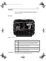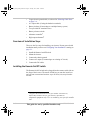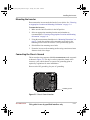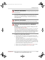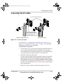
1
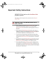
INVERTER 3000
t 1 408 987 6359
www.xantrex.com/support
Installation Guide
975-0445-01-01 REV. A
Printed in China
This guide for use by qualified installers only.
Inverter_3000_Install_Guide.book Page i Tuesday, June 3, 2008 12:22 PM
INVERTER 3000
Installation Guide
This guide for use by qualified installers only
Inverter_3000_Install_Guide.book Page ii Tuesday, June 3, 2008 12:22 PM
About Xantrex
Xantrex Technology Inc. is a world-leading supplier of advanced power electronics and controls with
products ranging from small mobile units to utility-scale systems for wind, solar, batteries, fuel cells,
microturbines, and backup power applications in both grid-connected and stand-alone systems. Xantrex
products include inverters, battery chargers, programmable power supplies, and variable speed drives
that convert, supply, control, clean, and distribute electrical power.
Trademarks
DURACELL® is a registered trademark of The Gillette Company, used under license. All rights
reserved. XANTREX is a registered trademark of Xantrex International.
Other trademarks, registered trademarks, and product names are the property of their respective owners
and are used herein for identification purposes only.
Notice of Copyright
Duracell® Inverter 3000 Installation Guide © May 2008 Duracell. All rights reserved.
Exclusion for Documentation
UNLESS SPECIFICALLY AGREED TO IN WRITING, XANTREX TECHNOLOGY INC. (“XANTREXTM”)
(A) MAKES NO WARRANTY AS TO THE ACCURACY, SUFFICIENCY OR SUITABILITY OF ANY TECHNICAL OR
OTHER INFORMATION PROVIDED IN ITS MANUALS OR OTHER DOCUMENTATION.
(B) ASSUMES NO RESPONSIBILITY OR LIABILITY FOR LOSSES, DAMAGES, COSTS OR EXPENSES, WHETHER
SPECIAL, DIRECT, INDIRECT, CONSEQUENTIAL OR INCIDENTAL, WHICH MIGHT ARISE OUT OF THE USE OF
SUCH INFORMATION. THE USE OF ANY SUCH INFORMATION WILL BE ENTIRELY AT THE USER ’S RISK; AND
(C) REMINDS YOU THAT IF THIS MANUAL IS IN ANY LANGUAGE OTHER THAN ENGLISH, ALTHOUGH
STEPS HAVE BEEN TAKEN TO MAINTAIN THE ACCURACY OF THE TRANSLATION, THE ACCURACY CANNOT
BE GUARANTEED. APPROVED XANTREX CONTENT IS CONTAINED WITH THE ENGLISH LANGUAGE
VERSION WHICH IS POSTED AT WWW.XANTREX.COM.
Date and Revision
May 2008 Revision A
Part Number
975-0445-01-01
Product Number
813-3007
Contact Information
Telephone: 1 408 987 6359
Website:
www.xantrex.com/support
This guide for use by qualified installers only
Inverter_3000_Install_Guide.book Page iii Tuesday, June 3, 2008 12:22 PM
About This Guide
Purpose
The purpose of this Installation Guide is to provide explanations and
procedures for installing the Duracell Inverter 3000.
Scope
The Guide provides safety guidelines, procedures for installing the
inverter. It does not provide details about particular brands of batteries.
You need to consult individual battery manufacturers for this information.
Refer to Duracell Inverter 3000 Owner’s Guide (doc. part number: 9750444-01-01) for operational instructions.
Audience
The Guide is intended for qualified installers including licensed
technicians and electricians. It is intended for installers with knowledge
and experience in installing electrical equipment, knowledge of the
applicable installation codes, and awareness of the hazards involved in
performing electrical work and how to reduce those hazards.
Organization
This Guide is organized into two chapters and one appendix.
Chapter 1 describes the standard features of the Duracell Inverter 3000, as
well as its protection features. It also provides information on the different
parts of the Duracell Inverter 3000.
Chapter 2 describes installation procedures including planning, wiring,
and mounting the Duracell Inverter 3000.
Appendix A contains physical and electrical specifications of the Duracell
Inverter 3000.
iii
This guide for use by qualified installers only
Inverter_3000_Install_Guide.book Page iv Tuesday, June 3, 2008 12:22 PM
About This Guide
Conventions Used
The following conventions are used in this guide.
WARNING
Warnings identify conditions that could result in personal injury or loss of life
CAUTION
Cautions identify conditions or practices that could result in damage to the unit or
other equipment.
Important: These notes describe things which are important for you to know,
but not as serious as a caution or warning.
Related Information
You can find more information about Xantrex Technology Inc. as well as
its products and services at www.xantrex.com
iv
975-0445-01-01
This guide for use by qualified installers only
Inverter_3000_Install_Guide.book Page v Tuesday, June 3, 2008 12:22 PM
Important Safety Instructions
IMPORTANT: Read and save this Installation Guide
for future reference.
This chapter contains important safety instructions for the Duracell
Inverter 3000.
WARNING: Shock, fire, and heat hazard. Risk of
injury to persons.
1. Before installing and using the Duracell Inverter 3000, read all
instructions and cautionary markings on or provided with the
Duracell Inverter 3000, the batteries, and all appropriate sections of
this guide.
2. Do not expose the Duracell Inverter 3000 to rain, snow, spray, or
bilge water. To reduce risk of fire hazard, do not cover or obstruct the
ventilation openings. Do not install the Duracell Inverter 3000 in a
zero-clearance compartment. Overheating may result.
3. To avoid a risk of fire and electric shock, make sure that existing
wiring is in good condition, adequately rated, and not undersized. Do
not operate the Duracell Inverter 3000 with damaged or substandard
wiring.
4. Do not install or operate the Duracell Inverter 3000 if it has received a
sharp blow, been dropped, or otherwise damaged in any way. If the
Duracell Inverter 3000 is damaged, see the Warranty section.
5. Do not disassemble the Duracell Inverter 3000. It contains no userserviceable parts. See Warranty for instructions on obtaining service.
Attempting to service the Duracell Inverter 3000 yourself may result
in a risk of electrical shock or fire. Internal capacitors remain charged
after all power is disconnected.
This guide for use by qualified installers only
v
Inverter_3000_Install_Guide.book Page vi Tuesday, June 3, 2008 12:22 PM
Safety
6. To reduce the risk of electrical shock, disconnect DC power from the
Duracell Inverter 3000 before attempting any maintenance or
cleaning or working on any circuits connected to the Duracell
Inverter 3000. Turning off controls will not reduce this risk.
7. The Duracell Inverter 3000 must be provided with equipmentgrounding conductors connected to the vehicle chassis as described in
“Chassis Ground Wire Sizing” on page 2–8 and “Output Conductor
Selection for Hardwire Installation” on page 2–8.
Precautions When Working With Batteries
WARNING: Explosion or fire hazard
1. Follow all instructions published by the battery manufacturer and the
manufacturer of the equipment in which the battery is installed to
reduce the risk of battery explosion.
2. Working in the vicinity of lead-acid batteries is dangerous. Batteries
generate explosive gases during normal operation. Therefore, you
must read this guide and follow the instructions exactly before
installing or using your Duracell Inverter 3000.
3. This equipment contains components which tend to produce arcs or
sparks. To prevent fire or explosion, do not install the Duracell
Inverter 3000 in compartments containing batteries or flammable
materials, or in locations that require ignition-protected equipment.
This includes any space containing gasoline-powered machinery, fuel
tanks, as well as joints, fittings, or other connections between
components of the fuel system.
4. Make sure the area around the battery is well ventilated.
5. Never smoke or allow a spark or flame near the engine or batteries.
6. Use caution to reduce the risk or dropping a metal tool on the battery.
It could spark or short circuit the battery or other electrical parts and
could cause an explosion.
7. If you need to remove a battery, always remove the ground terminal
from the battery first. Make sure all accessories are off so you don’t
cause a spark.
vi
This guide for use by qualified installers only
975-0445-01-01
Inverter_3000_Install_Guide.book Page vii Tuesday, June 3, 2008 12:22 PM
Safety
WARNING: Risk of personal injury due to burns or
battery acid
8. Remove all metal items, like rings, bracelets, and watches when
working with lead-acid batteries. Lead-acid batteries produce a short
circuit current high enough to weld metal to skin, causing a severe
burn.
9. Have someone within range of your voice or close enough to come to
your aid when you work near a lead-acid battery.
10. Have plenty of fresh water and soap nearby in case battery acid
contacts skin, clothing, or eyes.
11. Wear complete eye protection and clothing protection. Avoid
touching your eyes while working near batteries.
12. If battery acid contacts skin or clothing, wash immediately with soap
and water. If acid enters your eye, immediately flood it with running
cold water for at least twenty minutes and get medical attention
immediately.
Precautions for Using Rechargeable Appliances
CAUTION: Risk of equipment damage
The output of the Duracell Inverter 3000 is not sinusoidal and may not be
compatible with all loads. Follow the recommendations below.
Most rechargeable battery-operated equipment uses a separate charger or
transformer that is plugged into an AC receptacle and produces a low
voltage charging output.
Some chargers for small rechargeable batteries can be damaged if
connected to the Duracell Inverter 3000. Do not use the following with
the Duracell Inverter 3000:
•
•
975-0445-01-01
Small battery-operated appliances like flashlights, razors, and night
lights that can be plugged directly into an AC receptacle to recharge.
Some chargers for battery packs used in power hand tools. These
affected chargers display a warning label stating that dangerous
voltages are present at the battery terminals.
This guide for use by qualified installers only
vii
Inverter_3000_Install_Guide.book Page viii Tuesday, June 3, 2008 12:22 PM
viii
Inverter_3000_Install_Guide.book Page ix Tuesday, June 3, 2008 12:22 PM
Contents
Important Safety Instructions - - - - - - - - - - - - - - - - - - - - - - - - - - - - - - - - - - -v
1
Quality Power - - - - - - - - - - - - - - - - - - - - - - - - - - - - - - - - - - - - - - - - - - - - - - - - 1–1
Ease of Use - - - - - - - - - - - - - - - - - - - - - - - - - - - - - - - - - - - - - - - - - - - - - - - - - - 1–2
Comprehensive Protection - - - - - - - - - - - - - - - - - - - - - - - - - - - - - - - - - - - - - - - - 1–2
Features - - - - - - - - - - - - - - - - - - - - - - - - - - - - - - - - - - - - - - - - - - - - - - - - - - - - 1–3
AC Panel - - - - - - - - - - - - - - - - - - - - - - - - - - - - - - - - - - - - - - - - - - - - - - - - 1–3
DC Panel - - - - - - - - - - - - - - - - - - - - - - - - - - - - - - - - - - - - - - - - - - - - - - - - 1–5
Remote Switch - - - - - - - - - - - - - - - - - - - - - - - - - - - - - - - - - - - - - - - - - - - - 1–6
2
Designing Your Installation- - - - - - - - - - - - - - - - - - - - - - - - - - - - - - - - - - - - - - - 2–1
Installation Codes - - - - - - - - - - - - - - - - - - - - - - - - - - - - - - - - - - - - - - - - - - - 2–3
Calculating Battery Requirements - - - - - - - - - - - - - - - - - - - - - - - - - - - - - - - - 2–3
Choosing an Effective Charging System - - - - - - - - - - - - - - - - - - - - - - - - - - - 2–3
Choosing an Appropriate Location and Mounting Orientation - - - - - - - - - - - - - 2–4
Selecting Cable Sizes - - - - - - - - - - - - - - - - - - - - - - - - - - - - - - - - - - - - - - - - 2–6
DC Input Cables - - - - - - - - - - - - - - - - - - - - - - - - - - - - - - - - - - - - - - - - - 2–6
Selecting a DC Input Fuse or Circuit Breaker - - - - - - - - - - - - - - - - - - - - - 2–7
Chassis Ground Wire Sizing - - - - - - - - - - - - - - - - - - - - - - - - - - - - - - - - - 2–8
Output Conductor Selection for Hardwire Installation - - - - - - - - - - - - - - - 2–8
Installing the Inverter - - - - - - - - - - - - - - - - - - - - - - - - - - - - - - - - - - - - - - - - - - - 2–9
Safety Instructions - - - - - - - - - - - - - - - - - - - - - - - - - - - - - - - - - - - - - - - - - - 2–9
Installation Tools and Materials - - - - - - - - - - - - - - - - - - - - - - - - - - - - - - - - - 2–9
Tools - - - - - - - - - - - - - - - - - - - - - - - - - - - - - - - - - - - - - - - - - - - - - - - - 2–9
Materials - - - - - - - - - - - - - - - - - - - - - - - - - - - - - - - - - - - - - - - - - - - - - - 2–9
Overview of Installation Steps - - - - - - - - - - - - - - - - - - - - - - - - - - - - - - - - - 2–10
Installing the Remote On/Off Switch - - - - - - - - - - - - - - - - - - - - - - - - - - - - - 2–10
Mounting the Inverter - - - - - - - - - - - - - - - - - - - - - - - - - - - - - - - - - - - - - - - 2–11
Connecting the Chassis Ground - - - - - - - - - - - - - - - - - - - - - - - - - - - - - - - - 2–11
Connecting the AC Output - - - - - - - - - - - - - - - - - - - - - - - - - - - - - - - - - - - - 2–12
Connecting the DC Cables - - - - - - - - - - - - - - - - - - - - - - - - - - - - - - - - - - - - - - - 2–15
Electrical Performance - - - - - - - - - - - - - - - - - - - - - - - - - - - - - - - - - - - - - - - - - A–1
Physical Specifications - - - - - - - - - - - - - - - - - - - - - - - - - - - - - - - - - - - - - - - - - A–2
Accessory - - - - - - - - - - - - - - - - - - - - - - - - - - - - - - - - - - - - - - - - - - - - - - - - - - A–2
975-0445-01-01
This guide for use by qualified installers only
ix
Inverter_3000_Install_Guide.book Page x Tuesday, June 3, 2008 12:22 PM
x
Inverter_3000_Install_Guide.book Page 1 Tuesday, June 3, 2008 12:22 PM
1
Introduction
The Duracell Inverter 3000 has been designed to give you quality power,
ease of use, and reliability.
Please take a few moments to read this chapter to familiarize yourself
with the main performance features and protection features.
Quality Power
The Duracell Inverter 3000 is designed for use in recreational vehicles
(RVs), light and heavy duty truck applications, and other in-vehicle
applications.
• The inverter provides up to 2500 W of continuous power. It is
designed to handle loads such as microwaves, refrigerators, freezers,
circular saws, and small air compressors.
• The inverter’s high surge capability lets you handle many hard-tostart loads, including large TVs, refrigerators, and freezers.
• The cooling fan in the inverter is thermally activated and comes on
when the inverter becomes warm. The fan turns off automatically
after the inverter has cooled.
This guide for use by qualified installers only
1–1
Inverter_3000_Install_Guide.book Page 2 Tuesday, June 3, 2008 12:22 PM
Ease of Use
Superior features and rugged durability have been combined with ease of
use:
• The inverter is compact, lightweight, and easy to install.
• Loads can be powered directly from the AC outlets.
• Easy-to-read indicators on the front panel let you monitor system
performance at a glance.
• Remote On/Off switch (part number: 100-0864-01-01) lets you
control the inverter from a convenient location—up to 20 feet (6 m)
away—while the inverter itself is mounted out of sight.
Comprehensive Protection
The inverter is equipped with numerous protection features to guarantee
safe and trouble-free operation:
Low battery alarm Alerts you if the battery has become discharged to
11.0 V or lower.
Low battery voltage shutdown Shuts the inverter down automatically
if the battery voltage drops below 10.5 V. This feature will limit battery
discharge.
High battery voltage shutdown Shuts the inverter down automatically
if the input voltage rises to 15 V or more.
Overload and short-circuit shutdown Shuts the inverter down
automatically if a short-circuit is detected in the load connected to the
inverter’s output, or if the loads connected to the inverter exceed the
inverter’s operating limits.
Over-temperature shutdown Shuts the inverter down automatically if
its internal temperature rises above an acceptable level.
1–2
This guide for use by qualified installers only
975-0445-01-01
Inverter_3000_Install_Guide.book Page 3 Tuesday, June 3, 2008 12:22 PM
Features
Features
Chapter 1, “Introduction” describes the main features of the Duracell
Inverter 3000. Familiarize yourself with them before installing and
operating the inverter.
AC Panel
6
7
5
4
3
2
8
1
9
10
11
12
Figure 1-1 AC Panel
975-0445-01-01
Feature
Description
1
On/Off Switch turns the inverter’s control circuit on and off. This
switch is not a power disconnect switch. Disconnect AC and DC
power before working on any circuits connected to the inverter.
2
Fault light (red): indicates the inverter has shut down due to
inverter overload or over-temperature.
3
Power light (green): indicates the inverter is operating.
4
Display Function Button Press this to display battery voltage,
battery current and AC output power.
This guide for use by qualified installers only
1–3
Inverter_3000_Install_Guide.book Page 4 Tuesday, June 3, 2008 12:22 PM
1–4
Feature
Description
5
Status indicator lights: VOLTAGE, CURRENT, AC POWER
When lit, each light indicates which status is being displayed.
6
Status Display: Shows Voltage, Current or AC Power.
VOLTAGE: Indicates battery power at the input terminal of the
inverter in volts (V).
CURRENT: Indicates current drawn from the battery by the inverter
in amps (A).
AC POWER: Indicates the output power from the inverter as a
percentage of total available watts (kW) being utilized.
7
Two 15 A supplementary (overcurrent) breakers
8
3-Prong AC Outlets: Each outlet is protected by a 15-amp breaker.
9
AC Knockout: For hardwiring the inverter.
10
Remote On/Off Connector Port: For connecting the Remote On/
Off Switch.
11
Mounting Flanges (front and rear) allow you to mount the inverter
permanently.
12
Ventilation Openings must not be obstructed for the proper
operation of the inverter. When the inverter is mounted, the
ventilation opening on the DC panel must not point up or down.
This guide for use by qualified installers only
975-0445-01-01
Inverter_3000_Install_Guide.book Page 5 Tuesday, June 3, 2008 12:22 PM
Features
DC Panel
3
2
4
5
1
Figure 1-2 DC Panel
975-0445-01-01
Feature
Description
1
Chassis Ground Lug connects to vehicle chassis, DC grounding
bus or to engine’s negative bus.
2
Ventilation Opening must not be obstructed for the proper
operation of the inverter. When the inverter is mounted, the
ventilation opening on the DC panel must not point up or down.
3
Negative DC Cabling Terminal always connects to the cable
connected to the negative terminal of the battery.
4
Positive DC Cabling Terminal always connects to the cable
connected to the positive terminal of the battery.
5
Serial number of your inverter.
This guide for use by qualified installers only
1–5
Inverter_3000_Install_Guide.book Page 6 Tuesday, June 3, 2008 12:22 PM
Remote Switch
2
1
Figure 1-3 Remote Switch
1–6
Feature
Description
1
Remote On/Off Switch turns the inverter’s control circuit on and
off. This switch is not a power disconnect switch. Disconnect DC
power before working on any circuits connected to the inverter.
2
Communications Cable is 20 feet (6 m) long.
This guide for use by qualified installers only
975-0445-01-01
Inverter_3000_Install_Guide.book Page 1 Tuesday, June 3, 2008 12:22 PM
2
Installation
Chapter 2, “Installation,” provides information on cables and fuses to help
you plan for your installation and provide procedures for installing the
inverter.
Read the entire chapter before beginning the installation procedures so
that you can plan an installation that is suited to your power needs.
Designing Your Installation
Before doing anything else, you need to determine how you are going to
use your inverter, and then design a power system that will give you
maximum performance. The more thorough your planning, the better
your power needs will be met. In particular, you will need to:
•
•
•
•
•
•
Be aware of installation codes
Calculate your battery requirements
Choose an effective charging system
Choose an appropriate location and mounting orientation
Calculate the cable size for your inverter
Select the correct fuses or circuit breakers
Study Figures “Configuration for Normal Loads” on page 2–2 and
“Configuration for Heavy Loads” on page 2–2 for an example of a setup
for normal or heavy loads in a vehicle. When you have decided upon your
configuration, then you can calculate battery requirements.
This guide for use by qualified installers only
2–1
Inverter_3000_Install_Guide.book Page 2 Tuesday, June 3, 2008 12:22 PM
3000
Figure 2-1 Configuration for Normal Loads
3000
Figure 2-2 Configuration for Heavy Loads
2–2
This guide for use by qualified installers only
975-0445-01-01
Inverter_3000_Install_Guide.book Page 3 Tuesday, June 3, 2008 12:22 PM
Designing Your Installation
Installation Codes
Governing installation codes vary depending on the location and type of
installation. Electrical installations must meet local and/or national wiring
codes and should be performed by a qualified electrician.
An example of a national wiring code is the US National Electrical Code
(NEC, NFPA70) article 551 governing electrical installations in RVs. In
other geographical regions or for other applications, other codes will
apply. It is the installer's responsibility to identify and apply all
applicable codes.
Calculating Battery Requirements
Battery type and battery size strongly affect the performance of the
inverter. Therefore, you need to identify the type of loads your inverter
will be powering, and how much you will be using them between charges.
Once you know how much power you will be using, you can determine
how much battery capacity you need. We recommend that you purchase
as much battery capacity as possible.
For information on calculating battery capacity, go to www.xantrex.com,
click “Support”, choose the product “Xpower Inverters”, and click
“Battery Calculator” under Calculators & Problem Solvers.
CAUTION: Equipment damage
The inverter must only be connected to a 12 V battery system. It will not operate
if connected to a 6 V battery and will be damaged if connected to a 24 V battery.
Choosing an Effective Charging System
The charging system must be appropriate for your particular installation.
A well-designed charging system will ensure that power is available when
you need it and that your batteries remain in top condition. Inadequate
charging will degrade system performance, and the wrong type of charger
will reduce battery life.
For information about choosing an effective battery charging system, go
to www.xantrex.com, click “Support”, choose the product “Xpower
Battery Chargers”, and click “Selecting the Right battery Charger” under
Tech Notes.
NOTE: If the main charging source will be the vehicle's alternator, then
its voltage and current ratings must be appropriate for the size and type of
battery that is selected.
975-0445-01-01
This guide for use by qualified installers only
2–3
Inverter_3000_Install_Guide.book Page 4 Tuesday, June 3, 2008 12:22 PM
Choosing an Appropriate Location and Mounting Orientation
WARNING: Fire or explosion hazard
The inverter contains components which tend to produce arcs or sparks. To
prevent fire or explosion, do not install the Duracell Inverter 3000 in
compartments containing batteries or flammable materials, or in locations that
require ignition-protected equipment. This includes any space containing
gasoline-powered machinery, fuel tanks, as well as joints, fittings, or other
connections between components of the fuel system.
WARNING: Fire hazard
To reduce the risk of fire, do not cover or obstruct the ventilation openings. Do
not install the inverter in a zero-clearance compartment. Overheating may result.
Appropriate
Location
The inverter must only be installed in a location that is:
:
2–4
Dry
Do not allow water or other liquids to drop or splash on it.
Cool
Ambient air temperature should be between 0 and 40ºC
(32 and 105ºF)—the cooler the better within this range.
Ventilated
Allow at least 3" (76 mm) of clearance around the inverter
for air flow. Ensure that the ventilation openings on each
end of the inverter are not obstructed.
Safe
Do not install the inverter in the same compartment as
batteries or in any compartment capable of storing
flammable liquids like gasoline.
Close to
battery
Do not use excessive DC cable lengths: they increase wire
resistance which leads to voltage drop and heating.
Consequently, they reduce available power and run-time.
Longer AC wires are preferable to longer DC wires: voltage
drop is less of an issue and the cost is lower.
Protected
from battery
gases
Do not mount the inverter where it will be exposed to gases
produced by batteries. Battery gases are corrosive, and
prolonged exposure to battery gases will damage the
inverter.
This guide for use by qualified installers only
975-0445-01-01
Inverter_3000_Install_Guide.book Page 5 Tuesday, June 3, 2008 12:22 PM
Designing Your Installation
Mounting
Orientation
The inverter must be oriented in one of the following ways:
•
•
•
Horizontally on a vertical surface. (Do not mount with the fan
pointing up or down.)
On a horizontal surface.
Under a horizontal surface.
Figure 2-3 Approved Mounting Orientations
Mounting
Dimensions
Use the measurements below to plot the holes in the surface where you
want to anchor the inverter and permanently mount it into place.
450mm (17.7")
91.5mm (3.6")
126.5 (5")
Fastener diameter 5mm (0.2") max.
Figure 2-4 Mounting Dimensions (Not to scale)
975-0445-01-01
This guide for use by qualified installers only
2–5
Inverter_3000_Install_Guide.book Page 6 Tuesday, June 3, 2008 12:22 PM
Selecting Cable Sizes
To operate safely and effectively, the Duracell Inverter 3000 needs proper
cables and fuses. The Duracell Inverter 3000 has low-voltage and highcurrent input, so it is essential that you use low-resistance wiring between
the battery and the inverter. This means using the largest gauge and
shortest DC cables. The goal is to deliver the maximum amount of usable
energy to your load.
For safe and efficient operation, you will need to calculate cable sizes for
your:
•
•
DC input cables from the battery to inverter, and
Chassis ground cable from the vehicle chassis to the chassis ground
lug on the inverter’s DC panel.
WARNING: Fire hazard
Use only copper wire rated 90 °C minimum. Never use a DC input cable longer
than specified in “DC Input Cables” below. A longer cable can potentially
generate enough heat to start a fire or result in poor inverter performance.
DC Input Cables
•
•
•
•
•
Keep all cables as short as possible, and ensure that each cable
between the inverter and the battery is no longer than 10 feet (3 m).
Do not use aluminum cable. It has about 1/3 more resistance than
copper cable of the same size, and it is difficult to make good, lowresistance connections to aluminum wire.
Some installation codes require and we recommend use of oilresistant cable rated for damp or wet locations.
For installations subject to the US NEC, the minimum cable size
required is 75C, No. 4/0 AWG with a maximum fuse size of 400 Adc1
For other installations, other codes may apply, but in no case should
you use DC cables smaller than No. 2/0 AWG, protected by a
250 Adc fuse, but note that the five-minute 3000 W rating requires a
350 Adc fuse, which will require a minimum No. 4/0 AWG cable.
1.Based on US NEC, 2008, table 310-17, 75C copper wire.
2–6
This guide for use by qualified installers only
975-0445-01-01
Inverter_3000_Install_Guide.book Page 7 Tuesday, June 3, 2008 12:22 PM
Designing Your Installation
Selecting a DC Input Fuse or Circuit Breaker
The DC cables from the battery to the inverter need to be provided with
overcurrent protection, in the form of a fuse or circuit breaker, located as
close as possible to the DC positive battery terminal.
Because your batteries can provide thousands of amps of short-circuit
current, you need a DC-rated fuse or circuit breaker that can safely
interrupt the short-circuit current that the batteries can produce.
DC Disconnects
and OverCurrent Devices
The DC circuit from the battery to the inverter must be equipped with a
disconnect and over-current device. This usually consists of a circuit
breaker, a “fused-disconnect,” or a separate fuse and DC disconnect. Do
not confuse AC circuit breakers or fuses with DC-rated ones. They are not
interchangeable. The rating of the fuse or breaker must be matched to the
size of cables used in accordance with the applicable installation codes.
The breaker or disconnect switch and fuse should be located as close as
possible to the battery, in the positive cable. Applicable codes may limit
how far the protection can be from the battery.
To select the correct fuse type and size:
1. Determine the total short-circuit current rating for each battery, based
on the battery manufacturer's published short-circuit current sourcing
ratings for the battery. Then determine the total for your battery bank.
For example:
•
•
•
If you are using one battery to power your inverter and its shortcircuit current rating is 500 A, the total short-circuit current rating
is 500 A.
If you are powering your inverter with two 12 V batteries
connected in parallel, and each battery has a short-circuit current
rating of 500 A, the total short-circuit current rating is 1000 A.
If you are powering your inverter with two 6 V batteries
connected in series, and each battery has a short-circuit current
rating of 500 A, the total short-circuit current rating is 500 A.
Important: For batteries connected in parallel, the total short-circuit current
rating is the sum of the short-circuit current ratings of all of the batteries
connected in parallel. For batteries connected in series, the total short-circuit
current rating is equal to the short-circuit rating of the battery with the highest
short-circuit rating. It is not the sum of all the short-circuit current ratings taken
from each connected battery.
975-0445-01-01
This guide for use by qualified installers only
2–7
Inverter_3000_Install_Guide.book Page 8 Tuesday, June 3, 2008 12:22 PM
2. Once you have determined the total short-circuit current rating of
your batteries, select a fuse or circuit breaker that has:
•
•
•
a short-circuit interrupting capacity at least equal to the total
short-circuit current rating of your battery bank, and
a DC voltage rating of at least 16Vdc, and
a current rating no more than the values given above.
3. If a fuse is used rather than a circuit breaker, a disconnect switch
located between the battery and the fuse is recommended, to allow the
circuit to be de-energized when replacing the fuse.
Fuses and circuit breakers can be bought at any marine electrical
supply store, RV supply store, or electrical products store.
Chassis Ground Wire Sizing
Connect a minimum No. 8 AWG1 copper wire from the vehicle chassis to
the chassis ground terminal on the inverter DC panel.
Output Conductor Selection for Hardwire Installation
The inverter may be used by connecting cord-connected loads to the
receptacles on the front panel, and/or by connecting loads or a load circuit
to the AC output hardwire terminal block. If making connections to the
AC output hardwire terminal block, use jacketed No. 10 AWG2 copper 2wire plus ground cable. Conductors may be solid or stranded.
Some installation codes require and we recommend use of oil-resistant
cable rated for damp or wet locations.
Color code for conductors:
Black = [L]ine (hot)
White = [N]eutral
Bare or green = [G]round
1.Based on US NEC 2008 article 551-20(c). Other codes may require larger
chassis ground cable, in some cases as large as the DC power cables.
2.Based on US NEC 2008, table 310-16, 75C copper wire.
2–8
This guide for use by qualified installers only
975-0445-01-01
Inverter_3000_Install_Guide.book Page 9 Tuesday, June 3, 2008 12:22 PM
Installing the Inverter
Installing the Inverter
Do not proceed with the installation of your inverter until you have read
the section, “Designing Your Installation” starting on page 2–1. The more
thorough your planning, the better your power needs will be met to
achieve maximum performance from your inverter.
Safety Instructions
Before you start to install the inverter:
•
•
Review the “Important Safety Instructions” on page v.
Read and follow all Warnings and Cautions in this chapter.
Installation Tools and Materials
Tools
•
•
•
•
•
Wire stripper
Wrench for DC terminals
Screwdrivers (Philips, slotted)
Crimping tool for fastening lugs and terminals on DC cables.
NOTE: You may find it more convenient to have the crimp
connectors installed onto the DC cable by the store that sells you the
cable and/or connectors.
Hex key screwdriver, if set-screw type "box lugs" are used.
Materials
The following checklist is a general list of required materials.
•
•
•
•
•
975-0445-01-01
Four corrosion-resistant fasteners sized #10 or larger for mounting the
inverter
Copper DC input cable as selected in “DC Input Cables” on page 2–6.
Two 5/16" hole size ring terminals or box lugs, sized for the cable
gauge selected to connect the DC cables to the DC input terminals
Lugs and terminals to connect the DC cables that connect to the
battery fuse holder and disconnect switch
DC fuse(s), fuse holder, and disconnect switch, or DC circuit breaker,
as selected in “Selecting a DC Input Fuse or Circuit Breaker” on
page 2–7.
This guide for use by qualified installers only
2–9
Inverter_3000_Install_Guide.book Page 10 Tuesday, June 3, 2008 12:22 PM
•
•
•
Copper chassis ground cable, as selected in “Selecting Cable Sizes”
on page 2–6.
AC output cable (if using the hardwire terminals)
Battery isolator (if connecting to a multiple-battery system)
•
Two provided DC terminal covers1
•
Battery selector switch2
•
Alternator controller2
•
High-output alternator2
Overview of Installation Steps
These are the five steps for installing your inverter. Do not proceed with
installation until you have read “Designing Your Installation” starting on
page 2–1.
1. Install the Remote On/Off Switch.
2. Mount the inverter.
3. Connect the chassis ground.
4. Connect AC output (if connecting to an existing AC circuit).
5. Connect the DC cables.
Installing the Remote On/Off Switch
The Remote On/Off switch can be plugged into the remote switch jack on
the front of the inverter. The remote switch lets you turn the inverter on
and off from a convenient location—up to 20 feet (6 m) away from the
inverter.
1.Negative DC terminal black cover (part number: 064-3001-01),
Positive DC terminal red cover (part number: 064-3002-01)
2.Optional equipment only. Use as needed by your specific installa-
tion.
2–10
This guide for use by qualified installers only
975-0445-01-01
Inverter_3000_Install_Guide.book Page 11 Tuesday, June 3, 2008 12:22 PM
Installing the Inverter
Mounting the Inverter
Do not mount the inverter under the hood of your vehicle. See “Choosing
an Appropriate Location and Mounting Orientation” on page 2–4.
To mount the inverter:
1. Make sure the On/Off switch is in the Off position.
2. Select an appropriate mounting location and orientation as
recommended in “Choosing an Appropriate Location and Mounting
Orientation” on page 2–4.
3. Using the measurements found above in “Mounting Dimensions” on
page 2–5, mark the positions of the mounting screw holes in the
mounting surface where the inverter is to be permanently placed.
4. Pilot drill the four mounting screw holes.
5. Fasten the inverter to the mounting surface using corrosion-resistant
fasteners sized #10 or larger.
Connecting the Chassis Ground
The inverter has a lug connector labelled CHASSIS GND on the rear panel
as shown in Figure 2-5. This lug is used to connect the chassis of the
inverter to your vehicle chassis or system’s DC grounding point as
required by regulations for some installations.
Do not use the DC ground lug for your AC grounding.
Chassis ground
Figure 2-5 Chassis Ground Location
975-0445-01-01
This guide for use by qualified installers only
2–11
Inverter_3000_Install_Guide.book Page 12 Tuesday, June 3, 2008 12:22 PM
WARNING: Shock and fire hazard
Never operate the inverter without properly connecting the chassis ground.
You must connect the inverter chassis ground terminal to a grounding
point. Use a No. 8 AWG copper wire that is bare or provided with green
insulation and connect it between the inverter chassis ground lug and the
vehicle’s DC grounding point (usually the vehicle chassis or a dedicated
DC ground bus).
To connect the cable to the chassis ground lug:
1. Make sure the inverter’s On/Off switch is in the Off position.
2. Loosen chassis ground lug screw using a screwdriver.
3. Strip 3/8" (9.5 mm) of insulation from one end of the cable.
4. Place one end of the cable into the ground lug.
5. Tighten the chassis ground lug to a torque of 26.5–28.7 ft-lbs
(36–39 Nm).
Connecting the AC Output
You can plug your AC loads directly into the receptacle on the inverter
front panel. Output power to each receptacle is limited by a circuit
protector rated at 15 A.
You can also hardwire (permanently connect) the AC output using the AC
knockout. This is intended for connection of a load sub-panel or
additional AC outlets powered by the inverter.
Important: This connection must be made in accordance with applicable
electrical codes. If you are not a qualified electrician, we recommend that you let
a qualified electrician install this product.
WARNING: Fire and shock hazard
For protection and control, install a branch-circuit rated breaker between the
inverter and the load wiring, receptacles, and loads.
The Inverter 3000 will not operate a combination of high-power electrical
appliances that consume a total of more than 2500 watts (continuous
operation) or a total of more than 3000 watts (five-minute operation).
2–12
This guide for use by qualified installers only
975-0445-01-01
Inverter_3000_Install_Guide.book Page 13 Tuesday, June 3, 2008 12:22 PM
Installing the Inverter
WARNING: Shock hazard
If AC outlets are connected to the inverter AC hardwire terminal, the outlets must
be GFCI-protected.
For a list of Xantrex-tested and approved GFCIs and for more information
about GFCIs, see the application note “Using GFCI Receptacles on
Xantrex Inverters and Inverter/Chargers” in the Document Library at
www.xantrex.com.
WARNING: Shock hazard
Make sure wiring is disconnected from all electrical sources before handling.
WARNING: Shock hazard and risk of equipment
damage
Do not connect an AC source (such as a generator or utility power) to the
AC wiring output of the Inverter 3000.
The Inverter 3000 will not operate if its output is connected to AC voltage from
another source, and potentially hazardous or damaging conditions may occur.
These conditions can occur even if the inverter is off. If installing the inverter in
a system with another AC source (utility power or generator), an approved and
suitably rated break-before-make AC transfer switch must be installed
To make the AC output wiring connections:
1. Disconnect all DC and AC power sources from the Inverter 3000.
2. Install a dedicated AC load panel or an additional circuit breaker in an
existing AC load panel.
This circuit breaker must have a current rating based on the load
current the circuit will carry, and must be rated for 120 Vac branch
circuits. For installations subject to the US NEC, the required breaker
size is 30 A based on No. 10 AWG (using 75 °C minimum wire) and
the 2500 W continuous output rating of the inverter.
3. Remove the AC wiring knockout from the Inverter 3000 AC panel.
4. Remove the screws securing the Inverter 3000 AC panel.
975-0445-01-01
This guide for use by qualified installers only
2–13
Inverter_3000_Install_Guide.book Page 14 Tuesday, June 3, 2008 12:22 PM
5. Locate the terminal wires which are all terminated with a vinyl
insulated butt splice connector.
The output wires are colored white for (N)eutral, black for (L)ine, and
green (or bare) for (G)round.
6. Run the AC output cable through the knockout, and through an
appropriate strain-relief device.
7. Insert the ground (bare or green) wire into the butt splice connector
for the ground terminal.
8. Insert the Line (black) and Neutral (white) wires into the butt splice
connector for Line and butt splice connector for Neutral terminals,
respectively.
9. Secure and permanently attach each of the wires (L, N, and G) using a
butt splice connector crimping tool.
NOTE: Once the wires are crimped and secured, they cannot be
detached without cutting the wires, thus, you can only make these
connections one time.
WARNING: Shock hazard
Exposed and uncapped wires are a shock hazard. If you cut the wires after
permanently connecting the AC output wires make sure that you terminate the
wires with a proper wire cap terminal.
10. Complete the installation of the strain-relief device.
11. Replace the Inverter 3000 AC panel and secure the panel into place
using the screws from step #4.
12. Connect the outgoing AC wires to the AC load panel.
2–14
This guide for use by qualified installers only
975-0445-01-01
Inverter_3000_Install_Guide.book Page 15 Tuesday, June 3, 2008 12:22 PM
Connecting the DC Cables
Connecting the DC Cables
Do not remove the terminal nut
Do not place anything
between battery cable lug
and terminal surface.
Assemble exactly as shown.
Copper Compression Lug
Aluminum Box Lug
Figure 2-6 DC cable lug examples
Consult Figure 2-1, “Configuration for Normal Loads” on page 2–2, or
Figure 2-2, “Configuration for Heavy Loads” on page 2–2 for additional
details that are specific to your installation.
To make the DC connections:
1. Cut the cables to the correct length with enough insulation stripped off
so you can properly install the type of terminals you will be using.
The terminals on the DC end are designed to fit up to 500 MCM crimpon ring terminals (either AMP or ILSCO) or box connectors.
2. Attach the connectors to both cables.
If using compression lugs, attach the terminals to both cables using the
crimp tool recommended by the manufacturer of the ring terminals.
There must be no stray wire strands protruding from the terminal.
If using box lugs, attach the lug to the Duracell Inverter 3000 first, then
insert the wire and tighten the set screw to the torque recommended by
the lug manufacturer.
3. Route the DC supply cables from the battery bank to the inverter.
975-0445-01-01
This guide for use by qualified installers only
2–15
Inverter_3000_Install_Guide.book Page 16 Tuesday, June 3, 2008 12:22 PM
4. Install a fuse and disconnect switch or breaker between the inverter
and the battery. Ensure that the disconnect switch or breaker is turned
off before installing. They must be installed in the positive side of the
DC circuit, as close as possible to the battery. This protects your
battery and wiring in case of accidental shorting. See “Installing the
Inverter” on page 2–9.
5. Attach one connector on the positive cable to the positive DC
terminal on the DC end, and then attach the other connector to the
POSITIVE (+) terminal on the fuse or breaker.
CAUTION: Reverse polarity
DC power connections to the inverter must be positive to positive and negative to
negative. A reverse polarity connection (positive to negative) will blow a fuse in
the inverter and may permanently damage the inverter. The fuse is not user
replaceable and the inverter may need to be returned for servicing.
Damage caused by a reverse polarity connection is not covered by your warranty.
Observe the polarities carefully while completing the installation. Use
a wrench to tighten to a torque of 216–240 inch-pounds (24–27 Nm).
Test that the cable is secure.
CAUTION
Do not over-tighten the nut on the DC input terminals. Damage to the DC input
terminals may result.
CAUTION
Do not remove the terminal nut.
CAUTION
Loose connections cause excessive voltage drop and may cause overheated wires
and melted insulation.
2–16
This guide for use by qualified installers only
975-0445-01-01
Inverter_3000_Install_Guide.book Page 17 Tuesday, June 3, 2008 12:22 PM
Connecting the DC Cables
6. Connect one connector on the negative cable to the negative terminal on
the DC end. Before proceeding, check that cable polarity is correct, and
then connect the other end of the cable to the NEGATIVE (–) terminal
on the battery.
This is the last cable connection you make. If the disconnect switch or
breaker is not turned off, a spark is normal when the connection is made.
Use a wrench to tighten to a torque of 216–240 inch-pounds (24–27
Nm). Test that the cable is secure.
7. Attach the DC terminal covers.
8. Before proceeding, double check that you have connected the cables
properly—positive to positive, negative to negative.
9. Turn on the battery disconnect switch or breaker.
10. If you have installed a battery selector switch, use it to select one of the
batteries or battery banks (house bank preferred over start bank).
11. Move the inverter’s On/Off switch to the On position.
12. Check the input voltage display. It should read between 12 and 13 V,
depending on the condition of the battery. If it does not, check your
battery and the connection to the inverter, and the state of charge of the
battery.
13. Test sample loads by plugging appliances into the AC receptacles and
check to see if they work properly.
Alternatively, if a load sub-panel or additional AC outlets are hardwired
into the inverter AC output, test that appliances plugged into the
additional outlets are working properly.
975-0445-01-01
This guide for use by qualified installers only
2–17
Inverter_3000_Install_Guide.book Page 18 Tuesday, June 3, 2008 12:22 PM
2–18
This guide for use by qualified installers only
975-0445-01-01
Inverter_3000_Install_Guide.book Page 1 Tuesday, June 3, 2008 12:22 PM
A
Specifications
Appendix A contains electrical performance and physical specifications
for the inverter.
Important: Specifications are subject to change without notice.
Electrical Performance
Output power at 25ºC (77ºF) ambient
temperature and 12 Vdc input:
• Maximum continuous output power 2500 W
• 5 minute rating
3000 W
Output power at 40ºC (104ºF) ambient
temperature and 12 Vdc input:
• Maximum continuous output power 1900 W
Output current:
• Maximum continuous output
• 5 minute rating
20 Adc
25 Adc
Output voltage range
120 Vac RMS ± 10%
Output waveform
Modified sine wave
Output frequency
60 Hz
Input voltage range
10.5–15 Vdc (12.0 Vdc nominal)
Input current:
• Maximum continuous output
• 5 minute rating
260 A
300 A
Low battery alarm
11.0 V
Low battery cutout
10.5 V
Peak efficiency
90%
No load current draw (switch is on)
<0.6 Adc
This guide for use by qualified installers only
A–1
Inverter_3000_Install_Guide.book Page 2 Tuesday, June 3, 2008 12:22 PM
Physical Specifications
Length
18 1/2" (47 cm)
Width
8" (20 cm)
Height
6 1/4" (16 cm)
Weight
20 lb. (9 kg)
Remote On/Off switch with 20-foot
communications cable
Part number: 100-0864-01-01
Accessory
A–2
This guide for use by qualified installers only
975-0445-01-01