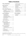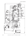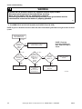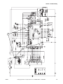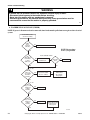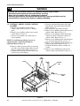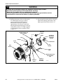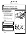
1
Service
Homestyle
Frontload
Washers
Refer to Page 5 for Model Numbers
FLW1509C
www.comlaundry.com
Part No. 800401R1
June 2007
Table of Contents
Section 1 – Safety Information
Locating an Authorized Servicer ............................4
Section 2 – Introduction
Customer Service ....................................................5
Nameplate Location ................................................5
Model Identification ................................................5
How Your Washer Works .......................................6
Section 3 – Washer Troubleshooting
1. No Spin Condition – Models through Serial No.
9811005968 ......................................................9
2. Troubleshooting Knocking Noise ......................9
3. No motor rotation, or drive failure code “E:df” on
electronic display units ...................................11
Section 4 – Troubleshooting
4. Washer Will Not Start
(Door Switch Analysis) ..................................16
5. Washer Will Not Start
(Door Lock Switch Analysis) ........................18
6. Washer Will Not Start (Timer) ......................20
7. Washer Will Not Start (Control Board) .........22
8. Washer Will Not Fill ......................................24
9. Washer Overflows .........................................26
10. Washer Will Not Pump ..................................28
Control System Faults ...........................................30
Washer “DC” Motor Functions ............................30
21.
22.
23.
24.
25.
26.
27.
28.
29.
30.
31.
32.
33.
34.
Graphic Panel (Control Panel Overlay) .........50
Lower Access Panel .......................................50
Electric Drain Pump .......................................51
Cabinet Top Assembly ...................................52
Mixing Valve .................................................53
Loading Door .................................................55
Front Panel .....................................................56
Door Seal And Hose Assembly .....................60
Door Switch ...................................................62
Door Latch Switch .........................................62
Inner Basket Pulley ........................................62
Outer Tub Front Panel ...................................66
Inner Basket Assembly ..................................67
Bearing Housing Assembly ...........................72
Section 7 – Adjustments
35.
36.
37.
38.
Cabinet Leveling Legs ...................................75
Loading Door .................................................76
Door Catch .....................................................77
Motor Belt ......................................................78
Section 5 – Grounding
11. Wall Receptacle Polarity Check ....................35
12. Machine Ground Connections
- Rear Control Washers ..................................36
13. Machine Ground Connections
- Front Control Washers .................................38
Section 6 – Service Procedures
14. Control Hood Assembly
– Rear Control Washers .................................41
15. Control Cabinet – Front Control Washers .....44
16. Timer ..............................................................45
17. Temperature Switch .......................................47
18. Pressure Switch ..............................................48
19. Motor Control Board ......................................48
20. Door Lock Indicator Light .............................49
© Copyright 2007, Alliance Laundry Systems LLC
All rights reserved. No part of the contents of this book may be reproduced or transmitted in any form or by any means without
the expressed written consent of the publisher.
800401
© Copyright, Alliance Laundry Systems LLC – DO NOT COPY or TRANSMIT
1
Notes
2
© Copyright, Alliance Laundry Systems LLC – DO NOT COPY or TRANSMIT
800401
Section 1
Safety Information
Throughout this manual and on machine decals, you will find precautionary statements (“CAUTION,”
“WARNING,” and “DANGER”) followed by specific instructions. These precautions are intended for the personal
safety of the operator, user, servicer and those maintaining the machine.
a DANGER
Danger indicates the presence of a hazard that will cause severe personal injury, death or substantial property
damage if the danger is ignored.
a WARNING
Warning indicates the presence of a hazard that can cause severe personal injury, death or substantial property
damage if the warning is ignored.
a CAUTION
Caution indicates the presence of a hazard that will or can cause minor personal injury or property damage if the
caution is ignored.
Additional precautionary statements (“IMPORTANT” and “NOTE”) are followed by specific instructions.
IMPORTANT
The word “IMPORTANT” is used to inform the reader of specific procedures where minor machine damage will
occur if the procedure is not followed.
NOTE
The word “NOTE” is used to communicate installation, operation, maintenance or servicing information that is
important but not hazard related.
In the interest of safety, some general precautions relating to the operation of this machine follow.
WARNING
• Failure to install, maintain and/or operate this product according to the manufacturer’s
instructions may result in conditions which can produce serious injury, death and/or property
damage.
• Do not repair or replace any part of the product or attempt any servicing unless specifically
recommended or published in this Service Manual and unless you understand and have the
skills to carry out the servicing.
• Whenever ground wires are removed during servicing, these ground wires must be
reconnected to ensure that the product is properly grounded and to reduce the risk of fire,
electric shock, serious injury or death.
W006R2
800401
© Copyright, Alliance Laundry Systems LLC – DO NOT COPY or TRANSMIT
3
Section 1 Safety Information
WARNING
To reduce the risk of electric shock, fire, explosion, serious injury or death:
• Disconnect electric power to the washer before servicing.
• Never start the washer with any guards/panels removed.
• Whenever ground wires are removed during servicing, these ground wires must be
reconnected to ensure that the washer is properly grounded.
W003
WARNING
Repairs that are made to your products by unqualified persons can result in hazards due to
improper assembly or adjustments subjecting you or the inexperienced person making such
repairs to the risk of serious injury, electrical shock or death.
W007
WARNING
If you or an unqualified person perform service on your product, you must assume the
responsibility for any personal injury or property damage which may result. The manufacturer
will not be responsible for any injury or property damage arising from improper service and/or
service procedures.
W008
NOTE: The WARNINGS and IMPORTANT INSTRUCTIONS appearing in this manual are not meant to
cover all possible conditions and situations that may occur. Common sense, caution and care must be
exercised when installing, maintaining or operating the washer.
Always contact your dealer, distributor, service agent or the manufacturer about any problems or conditions you do
not understand.
Locating an Authorized Servicer
Alliance Laundry Systems is not responsible for personal injury or property damage resulting from improper
service. Review all service information before beginning repairs.
Warranty service must be performed by an authorized technician, using authorized factory parts. If service is
required after the warranty expires, Alliance Laundry Systems also recommends contacting an authorized
technician and using authorized factory parts.
4
© Copyright, Alliance Laundry Systems LLC – DO NOT COPY or TRANSMIT
800401
Section 2
Introduction
Customer Service
If literature or replacement parts are required, contact
the source from whom the machine was purchased or
contact Alliance Laundry Systems at (920) 748-3950
for the name and address of the nearest authorized
parts distributor.
For technical assistance, call (920) 748-3121.
Nameplate Location
When calling or writing about your product, be sure to
mention model and serial numbers. Model and serial
numbers are located on nameplate(s) as shown.
NAMEPLATE
LOCATION
H129PE1A
Model Identification
Information in this manual is applicable to these washers.
FTS80A*H
FTU80A*H
FTZ80A*H
800401
LTS80A*E
LTS80A*H
LTZ80A*H1102
© Copyright, Alliance Laundry Systems LLC – DO NOT COPY or TRANSMIT
5
Section 2 Introduction
How Your Washer Works
MOTOR CONTROL
BOARD
(Located Inside
Control Hood)
TEMPERATURE
SELECTOR
TIMER
DISPENSER
DRAWER
MIXING
VALVE
INNER
BASKET
OUTER
TUB
MOTOR
FLW1362S
WATER
PUMP
REAR CONTROL MODELS
6
© Copyright, Alliance Laundry Systems LLC – DO NOT COPY or TRANSMIT
800401
Section 2 Introduction
TEMPERATURE
SELECTOR
MOTOR CONTROL
BOARD
(Located Inside
Control Cabinet)
TIMER
MIXING
VALVE
High Efficien
cy Washer
DISPENSER
DRAWER
INNER
BASKET
OUTER
TUB
MOTOR
FLW1157S
WATER
PUMP
FRONT CONTROL MODELS
800401
© Copyright, Alliance Laundry Systems LLC – DO NOT COPY or TRANSMIT
7
Section 2 Introduction
General
Technical
This frontload washer provides some of the same
principles of operation as the typical topload washers.
It senses water level, it dispenses the desired laundry
detergent, tumbles the clothes for good cleaning
action, pumps the water out of the washer and spins
the clothing for preparing for the dryer.
The basic operational controls of this washer consists
of the motor control logic board, timer, pressure
switch, temperature switch, D.C. motor and electric
pump.
The difference in operation is primarily the rotational
washing cycle that tumbles the clothes in a timer
controlled clockwise, pause and then a counterclockwise direction. This reversing cycled tumbling
action provides a much more efficient washing process
which requires less laundry detergent and less water.
The cycle begins by locking the loading door with a
wash fill command from the timer. The water
temperature is determined by the temperature selector.
While water fills the inner basket, a column of air is
trapped in a pressure bulb and hose. The air pressure
continues to increase as the inner basket fills with
water until it is great enough to activate the pressure
switch. The pressure switch then causes the wash fill
to stop and starts the reversing rotational washing
cycle.
The reversing rotational cycle tumbles the clothing in a
clockwise direction for a period of 20 seconds, pauses
for 9 seconds and then tumbles the clothing in a
counterclockwise direction for ten seconds. This
action continues until the completion of the wash cycle
selected on the timer.
Upon completion of the wash cycle, the machine goes
into a rinse cycle. The rinse cycle consists of a spin
mode that removes the majority of the detergent water
from the clothing and also activates the electric water
pump which removes the wash water. Fresh
temperature selected water is brought into the inner
basket via the mixing valve, the pressure switch shuts
off the water and then a rinse cycle starts. The rinse
cycle consists of a tumble reversing action similar to
the washing cycle for a pre-determined amount of
time, a spin mode, and includes water being pumped
out and fresh water being brought into the washer.
Several of these rinse cycles will take place, based
upon the operator timer wash type selection.
After all the rinse cycles have been completed, the
washer goes into a 1059 rpm final spin cycle for 90
seconds to extract as much water as possible from the
clothing, preparing them for the dryer. When this fast
spin cycle is completed, the washer goes into a fluff
tumble mode similar to agitate, only without water.
Operation stops and the loading door interlock is
deactivated allowing operator entry into the washer.
The principle of operation remains the same as other
washing machines. The door locks and starts the timer.
The timer starts the machine process by first having
the electronic control activate the dual water inlet
mixing valve which starts to fill the washer via the
dispenser mixing valve. The water temperature is
determined by the operator selected temperature
switch position, which selects the hot, cold or both
mixing valves. The second step is adding the detergent
and other washing ingredients. This process continues
until the air pressure, via the pressure bulb and hose,
activates the pressure switch, which overrides the
timer fill command.
The timer continues its rotational cycle, which then
sends the command to the motor control board to start
the timer rotator. The tumble rotating action is a
specific wash cycle rotation, pause and then reverse
rotation. This process continues for an operator’s
selected period of time.
The next command mode the timer signals to the
motor control board is to start the rinse cycle. This
cycle signals the electric pump to turn on and direct
the wash water out of the washer. The motor control
board then commands the motor to go into a faster spin
cycle in an attempt to remove a reasonable amount of
water out of the clothing. The spin cycle stops and
then adds fresh rinse water into the washer via the inlet
mixing valve and dispenser hose. After the pressure
switch shuts off the water inlet mixing valve, the
motor control board commands the motor to start the
normal wash rotational, pause, reverse direction
process for a timer controlled amount of time. This
rinse cycle is completed twice.
The next portion of the wash cycle is the spin cycle. In
this cycle the control board turns the electric pump on
to remove the rinse water from the tub. The washer
will spin at a distribution speed of 90 rpm until the
pressure switch is satisfied as empty. The washer then
goes to a 500 rpm spin for 30 seconds and returns to
the 90 rpm distribution speed for another 30 seconds.
This allows the motor control board to “sense” the outof-balance condition of the load. This sequence is
repeated any time the washer attempts to go to a spin
speed. At this time the washer then goes into a final
spin mode of 650 rpm for approximately 5 minutes
and ramps up to 1059* rpm for the remaining 90
seconds.
*(For Regular and Rinse and Spin cycles only).
8
© Copyright, Alliance Laundry Systems LLC – DO NOT COPY or TRANSMIT
800401
Section 3
Washer Troubleshooting
WARNING
To reduce the risk of electric shock, fire, explosion, serious injury or death:
• Disconnect electric power to the washer before servicing.
• Never start the washer with any guards/panels removed.
• Whenever ground wires are removed during servicing, these ground wires must be
reconnected to ensure that the washer is properly grounded.
W003
1. NO SPIN CONDITION – MODELS THROUGH SERIAL NO. 9811005968
A “no spin” condition could be the result of an open circuit in the wire harness or out-of-balance switch.
a. Check that the harness is still connected to the out-of-balance switch. The wiring diagram may show the outof-balance switch as a normally open switch which is incorrect. The switch is a normally closed switch.
b. To test the electrical circuit, disconnect electrical power to the washer.
c. Remove the “H3” connector from the motor control board.
d. Use an Ohm meter and check the black/white to violet/white wires. Circuit should read closed, an open
reading indicates a bad switch or wire harness problem.
e. Flex the harness at the plastic retainer and test the switch and if okay, the base wire harness has an open
circuit and MUST be replaced.
f. After replacing the wire harness, tape the harness wires to the left front shock 1 ½ inches from top of shock.
Refer to Figure 1.
IMPORTANT: Leave a minimum of 8 inches of slack between tape on shock and the plastic wire retainer on
the out-of-balance switch mounting bracket. Refer to Figure 1.
2. TROUBLESHOOTING KNOCKING NOISE
If a frontload washer produces a noise similar to a knock on a door, it might be due to a flat spot on the belt.
The knocking sound is made when the flat spot hits the pulley. The knocking may occur during a pulse spin
and fade after reaching a higher RPM.
To correct this condition, replace the washer belt.
800401
© Copyright, Alliance Laundry Systems LLC – DO NOT COPY or TRANSMIT
9
Section 3 Washer Troubleshooting
Out-Of-Balance
Switch
Ballast
Weight
Plastic
Wire
Retainer
Wire
Harness
(8 inch slack)
1-1/2
Inches
Left
Front
Shock
Washer
Base
Tape
H006BE3A
Figure 1
10
© Copyright, Alliance Laundry Systems LLC – DO NOT COPY or TRANSMIT
800401
Section 3 Washer Troubleshooting
WARNING
To reduce the risk of electric shock, fire, explosion, serious injury or death:
• Disconnect electric power to the washer before servicing.
• Never start the washer with any guards/panels removed.
• Whenever ground wires are removed during servicing, these ground wires must be
reconnected to ensure that the washer is properly grounded.
W003
3. NO MOTOR ROTATION, OR DRIVE FAILURE CODE “E:DF” ON ELECTRONIC DISPLAY
UNITS
NOTE: Verify that motor is receiving proper voltage. Disconnect electrical power to washer.
TEST PROCEDURE
a. At the rear of the washer, remove the lower access panel.
b. Reach in through the access panel opening and disconnect motor wire harness from motor.
c. Using an Ohmmeter, measure resistance at the terminals on the motor. Refer to Table 1.
Motor Resistance Values
TACH INPUT
Terminals 6-7
Approximately 15 Ohms
BRUSHES
Terminals 4-5
Less than 70 Ohms
WINDING
Terminals 1-3
Approximately 1.1 Ohms
WINDING
Terminals 1-2
Approximately 2.0-2.4 Ohms
WINDING
Terminals 2-3
Approximately 3.4 Ohms
NOTE: Resistance values may vary depending on type of Ohmmeter used.
Table 1
d. Replace motor if there is an open circuit on tach input (terminals 6-7) or winding circuits (terminals 1, 2 and
3), or if there is continuity between any terminal and the motor housing.
e. An open circuit between terminals 4 and 5 indicates a stuck or worn brush. Refer to appropriate service
procedure below.
SERVICE PROCEDURE: STUCK BRUSHES
a. Remove motor from washer.
b. Using a flashlight, view brushes through holes in motor end shield. Refer to Figure 2.
c. Inspect both brushes to determine if either brush braided wire is binding the brush movement. The braided
wire might be snagged on the seam in the corner of the metal brush holder. Refer to Figure 2.
NOTE: The copper braided wire should be located in the center of the brush assembly. If the braided wire
has fallen to the bottom of the brush, it will cause binding.
d. After determining which brush assembly is binding, carefully use the tip of a small screwdriver to unsnag
and reposition the braided wire. Refer to Figure 3. Make sure spring is making unobstructed contact with the
end of the brush. Rotate armature by hand to assure that brushes are seated.
e. Recheck resistance between motor terminals 4 and 5 to verify the brush position has been corrected.
f. Reinstall motor in washer.
g. Run washer through cycle to verify proper operation.
800401
© Copyright, Alliance Laundry Systems LLC – DO NOT COPY or TRANSMIT
11
Section 3 Washer Troubleshooting
Braided wire hangs
up on brush holder
Braided Copper
Wire
Brush
Holder
Brush
Spring
BRAIDED COPPER WIRE –
Must be positioned away from
this brush holder. Braided wire
should “loop” up and away
from bottom of brush holder.
Refer to Figure 3.
Spring Loaded
Brush
FLW971S
Figure 2
Brush
Holder
BRAIDED WIRE – Should
“loop” up and away from
bottom of brush holder.
Brush
Spring
FLW970S
Figure 3
12
© Copyright, Alliance Laundry Systems LLC – DO NOT COPY or TRANSMIT
800401
Section 3 Washer Troubleshooting
WARNING
To reduce the risk of electric shock, fire, explosion, serious injury or death:
• Disconnect electric power to the washer before servicing.
• Never start the washer with any guards/panels removed.
• Whenever ground wires are removed during servicing, these ground wires must be
reconnected to ensure that the washer is properly grounded.
W003
SERVICE PROCEDURE: WORN BRUSHES
a. Remove motor from washer.
b. Using a flashlight, view brushes through holes in motor end shield. Refer to Figure 4.
c. Inspect both brushes to determine if either brush is worn. Refer to Figures 4 and 5.
GOOD BRUSH
Brush
Holder
– Has visible amount of
brush material remaining.
Brush
Spring
Brush
FLW1648S
FLW1648S
Figure 4
d. Replace worn brushes with 738P3 Motor Brush Kit. Follow instructions provided in kit.
800401
© Copyright, Alliance Laundry Systems LLC – DO NOT COPY or TRANSMIT
13
Section 3 Washer Troubleshooting
WARNING
To reduce the risk of electric shock, fire, explosion, serious injury or death:
• Disconnect electric power to the washer before servicing.
• Never start the washer with any guards/panels removed.
• Whenever ground wires are removed during servicing, these ground wires must be
reconnected to ensure that the washer is properly grounded.
W003
WORN BRUSH
Brush
Holder
– Has no visible brush
material remaining.
Brush spring
resting against
brush holder.
Brush
Spring
FLW1649S
FLW1649S
Figure 5
SERVICE PROCEDURE: CLOGGED BRUSHES
a. Remove motor from washer.
b. Using a flashlight, view brushes through holes in motor end shield. Refer to Figure 4.
c. Inspect both brushes to determine if they are clogged due to a build-up of carbon dust.
d. If there is a visible amount of brush left, use a screwdriver or similar device to push brush back and forth to
loosen and remove dust. Refer to Figure 4.
14
© Copyright, Alliance Laundry Systems LLC – DO NOT COPY or TRANSMIT
800401
Section 4
Troubleshooting
WARNING
To reduce the risk of electric shock, fire, explosion, serious injury or death:
• Disconnect electric power to the washer before servicing.
• Never start the washer with any guards/panels removed.
• Whenever ground wires are removed during servicing, these ground wires must be
reconnected to ensure that the washer is properly grounded.
W003
FLOW CHARTS AND SCHEMATICS
FOUND ON THE FOLLOWING PAGES
ARE FOR MODELS COVERED IN THIS MANUAL.
800401
© Copyright, Alliance Laundry Systems LLC – DO NOT COPY or TRANSMIT
15
Section 4 Troubleshooting
WARNING
To reduce the risk of electric shock, fire, explosion, serious injury or death:
• Disconnect electric power to the washer before servicing.
• Never start the washer with any guards/panels removed.
• Whenever ground wires are removed during servicing, these ground wires must be
reconnected to ensure that the washer is properly grounded.
W003
4. WASHER WILL NOT START (DOOR SWITCH ANALYSIS)
NOTE: If power is disconnected and reconnected, timer knob must be pulled out to energize washer electrical
system.
NOTE: Check for mechanical
binding on the door. Make sure door
is closed.
16
© Copyright, Alliance Laundry Systems LLC – DO NOT COPY or TRANSMIT
800401
Section 4 Troubleshooting
2
1
800401
© Copyright, Alliance Laundry Systems LLC – DO NOT COPY or TRANSMIT
17
Section 4 Troubleshooting
WARNING
To reduce the risk of electric shock, fire, explosion, serious injury or death:
• Disconnect electric power to the washer before servicing.
• Never start the washer with any guards/panels removed.
• Whenever ground wires are removed during servicing, these ground wires must be
reconnected to ensure that the washer is properly grounded.
W003
5. WASHER WILL NOT START (DOOR LOCK SWITCH ANALYSIS)
NOTE: If power is disconnected and reconnected, timer knob must be pulled out to energize washer electrical
system.
Washer Will Not Start.
Door Will Not Lock.
(1) "AC"
Is There
Voltage at
Terminal 4
on Door
Switch?
NO
NOTE: Check for
mechanical binding on
door. Make sure door is
closed.
Connect Wiring Between Door Lock
Switch and Door Switch.
YES
(2) "AC"
Is There
Voltage Across
Door Lock
Actuator?
NO
(3) "AC"
Is
There
Voltage Between
Terminal "4" on
NO
Door Lock to
"H1-5" on
Control
Board?
YES
Is Control
Warning
Buzzer on?
NO
Change Inoperative
Control.
YES
YES
Change Inoperative
Door Lock Assembly.
18
Correct Wiring
Between
Door Lock and
Control Board.
Refer to Control
System Faults Sheet.
(Page 24).
© Copyright, Alliance Laundry Systems LLC – DO NOT COPY or TRANSMIT
H033SE3B
800401
Section 4 Troubleshooting
3
1
2
800401
© Copyright, Alliance Laundry Systems LLC – DO NOT COPY or TRANSMIT
19
Section 4 Troubleshooting
WARNING
To reduce the risk of electric shock, fire, explosion, serious injury or death:
• Disconnect electric power to the washer before servicing.
• Never start the washer with any guards/panels removed.
• Whenever ground wires are removed during servicing, these ground wires must be
reconnected to ensure that the washer is properly grounded.
W003
6. WASHER WILL NOT START (TIMER)
NOTE: If power is disconnected and reconnected, timer knob must be pulled out to energize washer electrical
system.
Washer Will Not Start.
(No Door Lock Only)
Is There
Power
Connected
to Washer?
NO
Connect Power and Run Washer.
NOTE: Be sure timer
is in a cycle position.
YES
Washer Still Will Not Run
Has
Timer Knob
Been Pulled
to Start
Wash Cycle?
NO
NO
Pull Timer Knob
and Run Cycle.
Did Washer
Start?
YES
NO
Run Cycle.
NO
(1) "AC"
Is There
Voltage at
"L1" Coming
Into Timer
Assembly?
NO
Correct Wiring
Between Door Switch
and "L1" on Timer.
NO
Refer to: "Washer
Will Not Start
(Door Switch)"
(Paragraph 1)
YES
(2) "AC"
Is There
Voltage at "MA"
Coming out
of Timer
Assembly?
NO
Change Timer.
YES
Is There
Voltage at "TS"
Coming out
of Timer
Assembly?
NO
Change Timer.
Refer to:
"Washer Will Not Start
(Control Board)"
(Paragraph 4)
YES
H034SE3B
20
© Copyright, Alliance Laundry Systems LLC – DO NOT COPY or TRANSMIT
800401
Section 4 Troubleshooting
2
1
800401
© Copyright, Alliance Laundry Systems LLC – DO NOT COPY or TRANSMIT
21
Section 4 Troubleshooting
WARNING
To reduce the risk of electric shock, fire, explosion, serious injury or death:
• Disconnect electric power to the washer before servicing.
• Never start the washer with any guards/panels removed.
• Whenever ground wires are removed during servicing, these ground wires must be
reconnected to ensure that the washer is properly grounded.
W003
7. WASHER WILL NOT START (CONTROL BOARD)
NOTE: If power is disconnected and reconnected, timer knob must be pulled out to energize washer electrical
system.
22
© Copyright, Alliance Laundry Systems LLC – DO NOT COPY or TRANSMIT
800401
Section 4 Troubleshooting
1
3
2
800401
© Copyright, Alliance Laundry Systems LLC – DO NOT COPY or TRANSMIT
23
Section 4 Troubleshooting
WARNING
To reduce the risk of electric shock, fire, explosion, serious injury or death:
• Disconnect electric power to the washer before servicing.
• Never start the washer with any guards/panels removed.
• Whenever ground wires are removed during servicing, these ground wires must be
reconnected to ensure that the washer is properly grounded.
W003
8. WASHER WILL NOT FILL
NOTE: If power is disconnected and reconnected, timer knob must be pulled out to energize washer electrical
system.
NOTE: There is a possibility that "Washer Will Not Run" sections
may have to be used to solve fill issues after this point.
NOTE: The selected cycle temperature will affect the voltage
check that needs to be performed on the fill valves.
24
© Copyright, Alliance Laundry Systems LLC – DO NOT COPY or TRANSMIT
800401
Section 4 Troubleshooting
2
3
4
1
800401
© Copyright, Alliance Laundry Systems LLC – DO NOT COPY or TRANSMIT
25
Section 4 Troubleshooting
WARNING
To reduce the risk of electric shock, fire, explosion, serious injury or death:
• Disconnect electric power to the washer before servicing.
• Never start the washer with any guards/panels removed.
• Whenever ground wires are removed during servicing, these ground wires must be
reconnected to ensure that the washer is properly grounded.
W003
9. WASHER OVERFLOWS
NOTE: If power is disconnected and reconnected, timer knob must be pulled out to energize washer electrical
system.
NOTE: There is a possibility that
"Washer Will Not Run" sections
may have to be used to solve fill
issues after this point.
NOTE: The selected cycle
temperature will affect the
voltage check that needs to be
performed on the fill valves.
26
© Copyright, Alliance Laundry Systems LLC – DO NOT COPY or TRANSMIT
800401
Section 4 Troubleshooting
2
3
1
800401
© Copyright, Alliance Laundry Systems LLC – DO NOT COPY or TRANSMIT
27
Section 4 Troubleshooting
WARNING
To reduce the risk of electric shock, fire, explosion, serious injury or death:
• Disconnect electric power to the washer before servicing.
• Never start the washer with any guards/panels removed.
• Whenever ground wires are removed during servicing, these ground wires must be
reconnected to ensure that the washer is properly grounded.
W003
10. WASHER WILL NOT PUMP
NOTE: If power is disconnected and reconnected, timer knob must be pulled out to energize washer electrical
system.
28
© Copyright, Alliance Laundry Systems LLC – DO NOT COPY or TRANSMIT
800401
Section 4 Troubleshooting
1
800401
© Copyright, Alliance Laundry Systems LLC – DO NOT COPY or TRANSMIT
2
29
Section 4 Troubleshooting
WARNING
To reduce the risk of electric shock, fire, explosion, serious injury or death:
• Disconnect electric power to the washer before servicing.
• Never start the washer with any guards/panels removed.
• Whenever ground wires are removed during servicing, these ground wires must be
reconnected to ensure that the washer is properly grounded.
W003
Control System Faults
Shown below are the system faults that will cause
control to shut down and sound the BUZZER
continuously until electrical power to washer is turned
off.
INOPERATIVE CONDITION
SERVICE CORRECTION
Triac in motor control board shorted.
Change control board. Check motor.
Motor tachometer feedback signal circuit open.
Correct wiring between control board and motor.
Change motor.
Motor circuit fuse blown.
Change “FUS1” on control board and check washer
cylinder. Motor for mechanical binding.
Motor fails to spin up to correct speed in
predetermined time.
Check washer cylinder. Motor for mechanical binding.
Change motor.
Control door lock relay contact failure.
Refer to “Washer Will Not Start” (Door lock switch
analysis). Refer to Paragraph 5.
Washer tries to agitate for more than 40 minutes after
water level is attained.
Check wiring to timer. Check voltage at timer. Change
timer.
Washer “DC” Motor Functions
Agitate
Spin
For agitate, the “DC” current will flow through the full
field (D1, D2) of motor. The washer agitation is
produced by reversing polarity of the rotor in motor.
This polarity switching takes place on control board.
For spin (0 - 650 rpm), the “DC” current will flow
through the full field (D1, D2) of motor. For high speed
spin (+ 650 rpm), the “DC” voltage will flow through
half the field (D1, D3) of motor.
• One direction RL3 and RL4 are not operated.
Refer to wiring schematic on following pages.
• The other direction RL3 and RL4 are operated.
Refer to wiring schematics on following pages.
30
© Copyright, Alliance Laundry Systems LLC – DO NOT COPY or TRANSMIT
800401
Section 4 Troubleshooting
MOTOR DC
POWER SUPPLY
RL6
FUS1
7 AMP
250 V
"DC" Voltage
RL4
RL3
RL5
1
D1
2
H2
5
4
3
3
1
2
4
D3
D2
6
A2
H5
2
1
5
7
DL
3
4
6
A1
TG
FIELD
ROTOR
TACH
H049SE3B
Motor Assembly
800401
© Copyright, Alliance Laundry Systems LLC – DO NOT COPY or TRANSMIT
31
Section 4 Troubleshooting
MOTOR DC
POWER SUPPLY
RL6
FUS1
7 AMP
250 V
"DC" Voltage
RL4
RL3
RL5
1
D1
2
H2
5
4
3
1
2
D3
D2
3
6
4
A2
5
H5
2
1
7
DL
3
4
6
A1
TG
FIELD
ROTOR
TACH
H050SE3B
Motor Assembly
32
© Copyright, Alliance Laundry Systems LLC – DO NOT COPY or TRANSMIT
800401
Section 4 Troubleshooting
MOTOR DC
POWER SUPPLY
RL6
FUS1
7 AMP
250 V
"DC" Voltage
RL4
RL3
RL5
1
D1
2
H2
5
4
3
1
2
D3
D2
6
3
4
5
A2
H5
2
1
7
DL
3
4
6
A1
TG
FIELD
ROTOR
TACH
H052SE3B
Motor Assembly
800401
© Copyright, Alliance Laundry Systems LLC – DO NOT COPY or TRANSMIT
33
Section 4 Troubleshooting
Notes
34
© Copyright, Alliance Laundry Systems LLC – DO NOT COPY or TRANSMIT
800401
Section 5
Grounding
WARNING
To reduce the risk of electric shock, fire, explosion, serious injury or death:
• Disconnect electric power to the washer before servicing.
• Never start the washer with any guards/panels removed.
• Whenever ground wires are removed during servicing, these ground wires must be
reconnected to ensure that the washer is properly grounded.
W003
11. WALL RECEPTACLE POLARITY CHECK
Refer to Figure 6
Ground
Neutral
L1
Neutral
Side
115±12
V.A.C.
Round
Grounding
Prong
0
V.A.C.
NOTE: Have a qualified
electrician check polarity of
wall receptacle. If a voltage
reading is measured other
than that illustrated, the
qualified electrician should
correct the problem.
115±12
V.A.C.
W011GE3A
Figure 6
800401
© Copyright, Alliance Laundry Systems LLC – DO NOT COPY or TRANSMIT
35
Section 5 Grounding
WARNING
To reduce the risk of electric shock, fire, explosion, serious injury or death:
• Disconnect electric power to the washer before servicing.
• Never start the washer with any guards/panels removed.
• Whenever ground wires are removed during servicing, these ground wires must be
reconnected to ensure that the washer is properly grounded.
W003
12. MACHINE GROUND CONNECTIONS - REAR CONTROL WASHERS
Refer to Figure 7
1
2
3
4
5
6
7
8
9
10
36
Ground to Control Panel Assembly
Ground to Motor Control Board
Ground to Control Hood
Ground Power Cord to Cabinet Top
Ground to Rear Access Panel
Ground to Motor
Ground to Drain Pump
Ground to Motor Bracket
Ground to Outer Tub
Ground to Outer Tub Front
© Copyright, Alliance Laundry Systems LLC – DO NOT COPY or TRANSMIT
800401
Section 5 Grounding
3
2
4
1
5
6
10
FLW1161G
8
7
9
Figure 7
REAR CONTROL WASHERS
800401
© Copyright, Alliance Laundry Systems LLC – DO NOT COPY or TRANSMIT
37
Section 5 Grounding
WARNING
To reduce the risk of electric shock, fire, explosion, serious injury or death:
• Disconnect electric power to the washer before servicing.
• Never start the washer with any guards/panels removed.
• Whenever ground wires are removed during servicing, these ground wires must be
reconnected to ensure that the washer is properly grounded.
W003
13. MACHINE GROUND CONNECTIONS - FRONT CONTROL WASHERS
Refer to Figure 8
1 Ground to Control Panel Assembly
2 Ground to Control Cabinet Base
3 Ground to Control Shield
4 Ground to Motor Control Board
5 Ground Power Cord to Control Cabinet
6 Grounding Hardware to Control Cabinet
7 Ground to Motor
8 Ground to Drain Pump
9 Ground to Motor Bracket
10 Ground to Outer Tub
11 Ground to Outer Tub Front
38
© Copyright, Alliance Laundry Systems LLC – DO NOT COPY or TRANSMIT
800401
Section 5 Grounding
5
4
3
2
1
6
Hig
hE
ffici
en
cy
Was
he
r
7
11
8
9
FLW1159G
10
Figure 8
FRONT CONTROL WASHERS
800401
© Copyright, Alliance Laundry Systems LLC – DO NOT COPY or TRANSMIT
39
Section 5 Grounding
Notes
40
© Copyright, Alliance Laundry Systems LLC – DO NOT COPY or TRANSMIT
800401
Section 6
Service Procedures
WARNING
To reduce the risk of electric shock, fire, explosion, serious injury or death:
• Disconnect electric power to the washer before servicing.
• Never start the washer with any guards/panels removed.
• Whenever ground wires are removed during servicing, these ground wires must be
reconnected to ensure that the washer is properly grounded.
W003
IMPORTANT: When reference is made to
directions (right or left) in this manual, it is from
operator’s position facing front of washer.
c. Carefully remove bottom front of hood from
clips on cabinet top.
d. Disconnect wires from components and
carefully remove components from hood
assembly.
14. CONTROL HOOD ASSEMBLY – REAR
CONTROL WASHERS
a. Remove three screws holding rear of hood
assembly to control hood rear panel. Refer to
Figure 9.
b. Pivot hood assembly forward on cabinet top.
Refer to Figure 9.
NOTE: Refer to wiring diagram when rewiring
component parts.
TO REMOVE CONTROL HOOD END
PANELS
Remove two screws holding each end panel to
control mounting plate. Refer to Figure 10.
Pivot
Hood
Forward
Hood
Attaching
Screws
W252IE1A
W169SE3B
Figure 9
800401
© Copyright, Alliance Laundry Systems LLC – DO NOT COPY or TRANSMIT
41
Section 6 Service Procedures
Top
Cover
Switch
Bracket
End Panel
Left
Temperature
Switch
Timer
Indicator
Light
End Panel
Right
Graphic
Panel
Control
Knob
Timer
Knob
Timer
Knob
Skirt
Control
Mounting
Plate
Screw
Motor
Control
Board
Pressure
Switch
Pressure
Hose
FLW1121S
Figure 10
42
© Copyright, Alliance Laundry Systems LLC – DO NOT COPY or TRANSMIT
800401
Section 6 Service Procedures
Cabinet
Top
Control
Shield
Control
Cabinet
Base
Pressure
Switch
Gusset
Motor
Control
Board
Control
Cabinet
Left
Rear
Control
Cabinet
Timer
Control
Cabinet
Right
Indicator
Light
Timer
Knob
Skirt
Timer
Knob
Temperature
Switch
Co
mm
erc
ial
Hig
h Eff
icie
nc
y Wa
sh
er
Control
Knob
Control
Panel
FLW1044B
Control
Panel
Overlay
Figure 11
800401
© Copyright, Alliance Laundry Systems LLC – DO NOT COPY or TRANSMIT
43
Section 6 Service Procedures
WARNING
To reduce the risk of electric shock, fire, explosion, serious injury or death:
• Disconnect electric power to the washer before servicing.
• Never start the washer with any guards/panels removed.
• Whenever ground wires are removed during servicing, these ground wires must be
reconnected to ensure that the washer is properly grounded.
W003
15. CONTROL CABINET – FRONT CONTROL
WASHERS
a. Remove screws holding control panel to
control cabinet. Refer to Figure 11. Remove
panel.
b. Remove screws holding cabinet top to control
cabinet. Refer to Figure 11.
c. If area or space permits, lift cabinet top to a
vertical position.
f. Unscrew timer knob from timer shaft (right
hand thread), then remove timer knob skirt.
Refer to Figure 11.
g. Pull temperature switch knob off shaft.
h. Remove screws holding control cabinet base to
control cabinet. Refer to Figure 11.
i. Remove screws holding control shield (with
controls attached) to bottom rear flange of
control cabinet. Refer to Figure 11.
j. Remove screws holding motor control board to
rear of control cabinet. Refer to Figure 11.
k. Remove screws holding control cabinet to top
flange of side panels. Refer to Figure 11.
l. Carefully lift control cabinet assembly off
washer.
m. Remove screws holding left, right and rear
control cabinets together. Refer to Figure 11.
NOTE: To avoid damage to hinges, be sure to
support top with a chain (not included) or
equivalent. Refer to Figure 12.
d. Remove cabinet top from washer by removing
nuts and carriage bolts holding cabinet top and
hinges to control cabinet. Refer to Figure 12.
e. Carefully lift cabinet top off washer and set out
of the way to prevent damage.
Rear
Hinges
Chain
Cabinet
Top
Carriage
Bolt
Nut
Hig
h Ef
fic
ienc
yW
as
he
r
FLW1162S
Figure 12
44
© Copyright, Alliance Laundry Systems LLC – DO NOT COPY or TRANSMIT
800401
Section 6 Service Procedures
WARNING
To reduce the risk of electric shock, fire, explosion, serious injury or death:
• Disconnect electric power to the washer before servicing.
• Never start the washer with any guards/panels removed.
• Whenever ground wires are removed during servicing, these ground wires must be
reconnected to ensure that the washer is properly grounded.
W003
16. TIMER
a. Rear Control Washers
(1) Unscrew timer knob from timer shaft (right
hand thread), then remove timer knob skirt.
(2) Remove three screws holding rear of hood
assembly to control hood rear panel. Refer
to Figure 9.
(3) Pivot hood assembly forward on cabinet
top. Refer to Figure 9.
(4) Remove two screws holding timer to
control hood mounting plate. Refer to
Figure 13.
NOTE: DO NOT attempt to repair timer.
(5) Disengage wire harness terminal block
plugs from timer by pressing in on movable
locking tabs (located on each side of
terminal block plug) and pulling away from
timer. Refer to Figure 13.
IMPORTANT: To avoid an open circuit, DO NOT
pull on terminal block wires when removing blocks
from timer as this could damage wires or terminal
crimping.
Before attaching wire harness terminal blocks to
timer, make sure all male terminals on timer are
straight and are capable of accepting terminals
from wire harness terminal blocks.
Locking
Tab
Control Hood
Assembly
(Rear Control
Washers)
Control Panel
(Front Control
Washers)
Terminal
Block
Plug
FLW1163S
Timer
Timer
Attaching
Screws
Figure 13
800401
© Copyright, Alliance Laundry Systems LLC – DO NOT COPY or TRANSMIT
45
Section 6 Service Procedures
WARNING
To reduce the risk of electric shock, fire, explosion, serious injury or death:
• Disconnect electric power to the washer before servicing.
• Never start the washer with any guards/panels removed.
• Whenever ground wires are removed during servicing, these ground wires must be
reconnected to ensure that the washer is properly grounded.
W003
(6) Seat horizontal and vertical tabs on front
plate of timer completely into slots on
control mounting plate. Refer to Figure 14.
(7) Tighten attaching screws between 12 to 18
inch pounds (1.6 to 2.4 Nm).
Control
Mounting
Plate
IMPORTANT: To avoid timer damage, do not allow
timer to be struck on corners, edges of frame, or on
timer shaft.
Timer
Attaching
Screws
Timer
Tabs
Slots
FLW1164S
Figure 14
46
© Copyright, Alliance Laundry Systems LLC – DO NOT COPY or TRANSMIT
800401
Section 6 Service Procedures
WARNING
To reduce the risk of electric shock, fire, explosion, serious injury or death:
• Disconnect electric power to the washer before servicing.
• Never start the washer with any guards/panels removed.
• Whenever ground wires are removed during servicing, these ground wires must be
reconnected to ensure that the washer is properly grounded.
W003
b. Front Control Washers
(1) Unscrew timer knob from timer shaft (right
hand thread), then remove timer knob skirt.
(2) Remove screws holding control panel to
control cabinet. Refer to Figure 11.
Remove panel.
(3) Remove screws holding cabinet top to
control cabinet. Refer to Figure 11.
(4) If area or space permits, lift cabinet top to a
vertical position.
NOTE: To avoid damage to hinges, be sure to
support top with a chain (not included) or
equivalent. Refer to Figure 12.
(5) Remove two screws holding timer to
control mounting plate. Refer to Figure 11.
NOTE: DO NOT attempt to repair timer.
(6) Disengage wire harness terminal block
plugs from timer by pressing in on movable
locking tabs (located on each side of
terminal block plug) and pulling away from
timer. Refer to Figure 13.
IMPORTANT: To avoid an open circuit, DO NOT
pull on terminal block wires when removing blocks
from timer as this could damage wires or terminal
crimping.
Before attaching wire harness terminal blocks to
timer, make sure all male terminals on timer are
straight and are capable of accepting terminals
from wire harness terminal blocks.
(7) Seat horizontal and vertical tabs on front
plate of timer completely into slots on
control mounting plate. Refer to Figure 14.
(8) Tighten attaching screws between 12 to 18
inch pounds (1.6 to 2.4 Nm).
IMPORTANT: To avoid timer damage, do not allow
timer to be struck on corners, edges of frame, or on
timer shaft.
17. TEMPERATURE SWITCH
a. Rear Control Washers
(1) Remove three screws holding rear of hood
assembly to control hood rear panel. Refer
to Figure 9.
(2) Pivot hood assembly forward on cabinet
top. Refer to Figure 9.
(3) Disconnect wires from switch terminals.
NOTE: Refer to wiring diagram when rewiring
switch.
(4) Refer to Figure 10 for switch removal.
(5) Press in on two locking tabs and at the same
time turn switch 1/4 turn counterclockwise
to remove switch from switch bracket.
Refer to Figure 10.
IMPORTANT: Before removing switch, note switch
position in relation to switch bracket so switch can
be reinstalled in same position.
NOTE: When installing switch, place switch tabs
into cutout in switch bracket and turn switch
clockwise to its full limit of travel, within the switch
bracket opening, until both locking tabs snap into
place.
b. Front Control Washers
(1) Remove screws holding control panel to
control cabinet. Refer to Figure 11.
Remove panel.
(2) Remove screws holding cabinet top to
control cabinet. Refer to Figure 11.
(3) If area or space permits, lift cabinet top to a
vertical position.
NOTE: To avoid damage to hinges, be sure to
support top with a chain (not included) or
equivalent. Refer to Figure 12.
(4) Disconnect wires from switch terminals.
NOTE: Refer to wiring diagram when rewiring
switch.
(5) Remove screws holding temperature switch
to control panel. Refer to Figure 11.
800401
© Copyright, Alliance Laundry Systems LLC – DO NOT COPY or TRANSMIT
47
Section 6 Service Procedures
WARNING
To reduce the risk of electric shock, fire, explosion, serious injury or death:
• Disconnect electric power to the washer before servicing.
• Never start the washer with any guards/panels removed.
• Whenever ground wires are removed during servicing, these ground wires must be
reconnected to ensure that the washer is properly grounded.
W003
18. PRESSURE SWITCH
a. Rear Control Washers
(1) Remove three screws holding rear of hood
assembly to control hood rear panel. Refer
to Figure 9.
(2) Pivot hood assembly forward on cabinet
top. Refer to Figure 9.
(3) Disconnect wires from pressure switch.
Refer to wiring diagram when rewiring
switch.
(4) Refer to Figure 10 for switch removal.
IMPORTANT: Before connecting hose to pressure
switch, blow air through pressure hose to remove
any condensation that may have accumulated in
hose.
b. Front Control Washers
(1) Remove screws holding control panel to
control cabinet. Refer to Figure 11.
Remove panel.
(2) Remove screws holding cabinet top to
control cabinet. Refer to Figure 11.
(3) If area or space permits, lift cabinet top to a
vertical position.
NOTE: To avoid damage to hinges, be sure to
support top with a chain (not included) or
equivalent. Refer to Figure 12.
(4) Disconnect wires from pressure switch.
Refer to wiring diagram when rewiring
switch.
(5) Refer to Figure 11 for switch removal.
IMPORTANT: Before connecting hose to pressure
switch, blow air through pressure hose to remove
any condensation that may have accumulated in
hose.
19. MOTOR CONTROL BOARD
a. Rear Control Washers
(1) Remove three screws holding rear of hood
assembly to control hood rear panel. Refer
to Figure 9.
(2) Pivot hood assembly forward on cabinet
top. Refer to Figure 9.
(3) Disconnect harness connectors from
control board.
NOTE: Refer to wiring diagram when rewiring
control board.
IMPORTANT: Remove control board and metal
mounting plate as a unit. Handle control board by
the back metal plate. Do not contact control board
with hands or metal objects. Place assembly in
clean, dry area away from work area to avoid
damage. Do not attempt field repair of the motor
control board. Attempted repair or tampering with
the control board will void its warranty.
(4) Remove four screws holding motor control
board to control hood rear panel. Refer to
Figure 10.
(5) Remove control board and place in antistatic shipping material for return to
manufacturer.
IMPORTANT: It is important to take care when
handling original control. It must be carefully
placed in anti-static shipping material which was
removed from new control. Warranty credit will not
be issued if control is not wrapped properly.
b. Front Control Washers
(1) Remove screws holding control panel to
control cabinet. Refer to Figure 11.
Remove panel.
(2) Remove screws holding cabinet top to
control cabinet. Refer to Figure 11.
(3) If area or space permits, lift cabinet top to a
vertical position.
NOTE: To avoid damage to hinges, be sure to
support top with a chain (not included) or
equivalent. Refer to Figure 12.
48
© Copyright, Alliance Laundry Systems LLC – DO NOT COPY or TRANSMIT
800401
Section 6 Service Procedures
WARNING
To reduce the risk of electric shock, fire, explosion, serious injury or death:
• Disconnect electric power to the washer before servicing.
• Never start the washer with any guards/panels removed.
• Whenever ground wires are removed during servicing, these ground wires must be
reconnected to ensure that the washer is properly grounded.
W003
(4) Disconnect harness connectors from
control board.
NOTE: Refer to wiring diagram when rewiring
control board.
IMPORTANT: Remove control board and metal
mounting plate as a unit. Handle control board by
the back metal plate. Do not contact control board
with hands or metal objects. Place assembly in
clean, dry area away from work area to avoid
damage. Do not attempt field repair of the motor
control board. Attempted repair or tampering with
the control board will void its warranty.
(5) Remove four screws holding motor control
board to rear control cabinet. Refer to
Figure 11.
(6) Remove control board and place in antistatic shipping material for return to
manufacturer.
b. Front Control Washers
(1) Remove screws holding control panel to
control cabinet. Refer to Figure 11.
Remove panel.
(2) Remove screws holding cabinet top to
control cabinet. Refer to Figure 11.
(3) If area or space permits, lift cabinet top to a
vertical position.
NOTE: To avoid damage to hinges, be sure to
support top with a chain (not included) or
equivalent. Refer to Figure 12.
(4) Disconnect two wires from door lock
indicator light.
NOTE: Refer to wiring diagram when rewiring
light.
(5) Refer to Figure 11 for light removal.
IMPORTANT: It is important to take care when
handling original control. It must be carefully
placed in anti-static shipping material which was
removed from new control. Warranty credit will not
be issued if control is not wrapped properly.
20. DOOR LOCK INDICATOR LIGHT
a. Rear Control Washers
(1) Remove three screws holding rear of hood
assembly to control hood rear panel. Refer
to Figure 9.
(2) Pivot hood assembly forward on cabinet
top. Refer to Figure 9.
(3) Carefully remove bottom front of hood
from clips on cabinet top.
(4) Disconnect two wires from door lock
indicator light.
NOTE: Refer to wiring diagram when rewiring
light.
(5) Refer to Figure 10 for light removal.
800401
© Copyright, Alliance Laundry Systems LLC – DO NOT COPY or TRANSMIT
49
Section 6 Service Procedures
WARNING
To reduce the risk of electric shock, fire, explosion, serious injury or death:
• Disconnect electric power to the washer before servicing.
• Never start the washer with any guards/panels removed.
• Whenever ground wires are removed during servicing, these ground wires must be
reconnected to ensure that the washer is properly grounded.
W003
21. GRAPHIC PANEL (Control Panel Overlay)
a. Rear Control Washers
(1) Unscrew timer knob from timer shaft (right
hand thread), then remove timer knob skirt.
Refer to Figure 10.
(2) Pull temperature switch knob off shaft.
(3) Remove door lock light lenses. Refer to
Figure 10.
(4) Remove three screws holding rear of hood
assembly to control hood rear panel. Refer
to Figure 9.
(5) Pivot hood assembly forward on cabinet
top. Refer to Figure 9.
(6) Carefully remove bottom front of hood
from clips on cabinet top.
(7) Disconnect wires from components and
carefully remove components from control
mounting plate.
NOTE: Refer to wiring diagram when rewiring
component parts.
(8) Remove screws holding both end panels to
control hood assembly. Refer to Figure 10.
(9) Bend tabs on graphic panel (located inside
of control hood) straight out toward rear of
hood.
(10) Carefully remove graphic panel off front of
control mounting plate. Refer to Figure 10.
b. Front Control Washers
(1) Unscrew timer knob from timer shaft (right
hand thread), then remove timer knob skirt.
Refer to Figure 11.
(2) Pull temperature switch knob off shaft.
(3) Remove 4 screws holding control panel
overlay to control panel. Refer to
Figure 11.
50
22. LOWER ACCESS PANEL
a. While supporting the lower access panel,
remove two screws from bottom edge of lower
access panel. Refer to Figure 15.
b. Gently lower the access panel to disengage
panel locators from bottom edge of front panel.
Lower
Access
Panel
Screw
H024SE1A
Figure 15
© Copyright, Alliance Laundry Systems LLC – DO NOT COPY or TRANSMIT
800401
Section 6 Service Procedures
WARNING
To reduce the risk of electric shock, fire, explosion, serious injury or death:
• Disconnect electric power to the washer before servicing.
• Never start the washer with any guards/panels removed.
• Whenever ground wires are removed during servicing, these ground wires must be
reconnected to ensure that the washer is properly grounded.
W003
23. ELECTRIC DRAIN PUMP
a. While supporting the lower access panel,
remove two screws from bottom edge of lower
access panel. Refer to Figure 15.
b. Gently lower the access panel to disengage
panel locators from bottom edge of front panel.
Outer
Tub-to-Pump
Hose
c. Loosen hose clamps and remove three hoses
connected to electric drain pump (outer-tub-topump hose, vent hose and drain hose). Refer to
Figure 16.
d. Remove three mounting screws holding pump
to base.
Backflow
Preventer
Mounting
Screws
Drain
Hose
Mounting
Screw
Vent
Hose
Electric
Drain Pump
H210S31A
Figure 16
(continued)
800401
© Copyright, Alliance Laundry Systems LLC – DO NOT COPY or TRANSMIT
51
Section 6 Service Procedures
WARNING
To reduce the risk of electric shock, fire, explosion, serious injury or death:
• Disconnect electric power to the washer before servicing.
• Never start the washer with any guards/panels removed.
• Whenever ground wires are removed during servicing, these ground wires must be
reconnected to ensure that the washer is properly grounded.
W003
24. CABINET TOP ASSEMBLY
a. Rear Control Washers
(1) While supporting lower access panel,
remove two screws from bottom edge of
panel and remove panel. Refer to
Figure 15.
(2) Using the special tool, No. 318P4, remove
dispenser drawer. Refer to Figure 20.
(3) Open loading door. Carefully remove wire
clamp ring from groove with small flat
blade screwdriver. Spring is in 6 o’clock
position.
NOTE: To avoid damage to spring, use screwdriver
on wire clamp ring to the right or left of spring.
(4) Grasp loading door seal lip. Refer to
Figure 22, Step 1.
NOTE: To avoid damage to door seal, DO NOT use
pliers or sharp objects to grasp the door seal lip. If
lip is damaged, seal will leak.
(5) Using a circular motion, pull seal up
(Figure 22, Step 1), out (Figure 22, Step 2)
and down (Figure 22, Step 3).
(6) When seal releases from lip of front panel,
pull out and remove the seal from front
panel around door opening. Refer to
Figure 22, Step 4.
(7) Remove bottom two front panel attaching
screws. Refer to Figure 21.
(8) Remove front panel (with loading door
attached) away from washer as far as wires
permit.
(9) Unplug wire harness from both the door
latch switch and from the door switch.
Refer to Figure 23. Remove clips holding
wire harness and door seal hose along top
flange of front panel and remove front
panel.
(10) Remove two screws holding front of
cabinet top to front flange of side panels.
Refer to Figure 17.
52
Cabinet Top
Hold-Down
Screws
FLW1737S
Figure 17
(11) Remove three screws holding hood
assembly to control hood rear panel. Refer
to Figure 9.
(12) Pivot hood assembly forward on cabinet
top. Refer to Figure 9.
(13) Disconnect hose from pressure switch and
push hose down through hole in cabinet
top.
(14) Disconnect wire harnesses and wires.
(15) Reinstall control hood assembly.
(16) Lift front of cabinet top slightly and pull
forward to disengage from rear hold down
brackets.
(17) Carefully lift cabinet top off washer and set
alongside the washer cabinet on protective
padding.
© Copyright, Alliance Laundry Systems LLC – DO NOT COPY or TRANSMIT
800401
Section 6 Service Procedures
WARNING
To reduce the risk of electric shock, fire, explosion, serious injury or death:
• Disconnect electric power to the washer before servicing.
• Never start the washer with any guards/panels removed.
• Whenever ground wires are removed during servicing, these ground wires must be
reconnected to ensure that the washer is properly grounded.
W003
b. Front Control Washers
(1) Remove screws holding control panel to
control cabinet. Refer to Figure 11.
Remove panel.
(2) Remove screws holding cabinet top to
control cabinet. Refer to Figure 11.
(3) If area or space permits, lift cabinet top to a
vertical position.
NOTE: To avoid damage to hinges, be sure to
support top with a chain (not included) or
equivalent. Refer to Figure 12.
(4) Remove cabinet top from washer by
removing nuts and carriage bolts holding
cabinet top and hinges to control cabinet.
Refer to Figure 12.
(5) Carefully lift cabinet top off washer and set
out of the way to prevent damage.
25. MIXING VALVE
a. Mixing valve is located on upper back right
corner of rear panel. Refer to Figure 18.
b. Shut off external hot and cold water supply and
remove two inlet hoses.
c. Loosen hose clamp and remove mixing valveto-dispenser hose at the mixing valve. Refer to
Figure 18.
d. Remove wire harness disconnect blocks from
mixing valve solenoid terminals. Refer to
Figure 18.
NOTE: Refer to wiring diagram when rewiring
solenoids.
e. Go to rear of washer and remove screw holding
mixing valve and plate to rear panel, then
remove valve and plate out through opening in
rear panel. Refer to Figure 18.
f. Remove screws holding valve to mixing valve
plate. Refer to Figure 18.
800401
© Copyright, Alliance Laundry Systems LLC – DO NOT COPY or TRANSMIT
53
Section 6 Service Procedures
Mixing Valve-toDispenser Hose
Hose
Clamp
Hose
Clamp
Inlet
Hose
Backflow
Preventer
Control
Hood
(Rear Control)
Control
Cabinet
(Front Control)
Screws
Control
Shield
Mixing
Valve
Mixing
Valve
Plate
Rear
Panel
Mounting
Clip
H042PE3B
Wire Harness
Disconnect
Blocks
Figure 18
54
© Copyright, Alliance Laundry Systems LLC – DO NOT COPY or TRANSMIT
800401
Section 6 Service Procedures
WARNING
To reduce the risk of electric shock, fire, explosion, serious injury or death:
• Disconnect electric power to the washer before servicing.
• Never start the washer with any guards/panels removed.
• Whenever ground wires are removed during servicing, these ground wires must be
reconnected to ensure that the washer is properly grounded.
W003
26. LOADING DOOR
a. Unlatch and open loading door.
b. Remove door bezel by prying inside lip up and
forward with fingers. Refer to Figure 19.
c. While supporting loading door, remove screws,
lockwashers and nuts holding loading door to
hinge assembly and remove door. Refer to
Figure 19.
Door Bezel
Attaching
Screw
Door
Bezel
Inner
Door and
Glass
Hinge
Assembly
Nut
Lockwasher
Door
and
Glass
Screw
H212SE1A
Figure 19
800401
© Copyright, Alliance Laundry Systems LLC – DO NOT COPY or TRANSMIT
55
Section 6 Service Procedures
WARNING
To reduce the risk of electric shock, fire, explosion, serious injury or death:
• Disconnect electric power to the washer before servicing.
• Never start the washer with any guards/panels removed.
• Whenever ground wires are removed during servicing, these ground wires must be
reconnected to ensure that the washer is properly grounded.
W003
27. FRONT PANEL
a. Rear Control Washers
(1) While supporting the lower access panel,
remove two screws from bottom edge of
lower access panel. Refer to Figure 15.
(2) Gently lower the access panel to disengage
panel locators from bottom edge of front
panel.
(3) Using the Special Tool, No. 318P4, remove
dispenser drawer. Refer to Figure 20.
Pull Out
Drawer
Slightly
S
O
X
A
M
Remove
Drawer From
Housing
F
T
E
N
E
R
B
X
A
M
L
E
A
C
H
S
O
X
A
M
F
T
E
N
E
R
B
X
A
M
L
E
A
C
H
318P4
Dispenser
Drawer
Tool
Insert
Tool
H125S
Figure 20
(4) Unplug wire harness from both the door
latch switch and from the door switch.
Refer to Figure 23. Remove clips holding
wire harness and door seal hose along top
flange of front panel and remove front
panel.
NOTE: Door seal hose and wire harness must be
reinstalled in the appropriate clips and holes along
top flange of front panel. Refer to Figure 21.
(5) Open loading door. Carefully remove wire
clamp ring from groove with small flat
screwdriver. Spring is in 6 o’clock position.
NOTE: To avoid damage to spring, use screwdriver
on wire clamp ring to the right or left of spring.
(6) Grasp loading door seal lip. Refer to
Figure 22, Step 1.
56
NOTE: To avoid damage to door seal, DO NOT use
pliers or sharp objects to grasp the door seal lip. If
lip is damaged, seal will leak.
(7) Using a circular motion, pull seal up
(Figure 22, Step 1), out (Figure 22, Step 2)
and down (Figure 22, Step 3).
(8) When seal releases from lip of front panel,
pull out and remove the seal. Refer to
Figure 22, Step 4.
NOTE: The ease of installation of the loading door
seal can be improved using water or 409 lubricant to
work seal around circumference of loading door. Be
sure to orientate seal with the white arrow in the 12
o’clock position when installing the wire clamp ring
to front panel. Be careful not to overstretch tension
spring.
© Copyright, Alliance Laundry Systems LLC – DO NOT COPY or TRANSMIT
800401
Section 6 Service Procedures
WARNING
To reduce the risk of electric shock, fire, explosion, serious injury or death:
• Disconnect electric power to the washer before servicing.
• Never start the washer with any guards/panels removed.
• Whenever ground wires are removed during servicing, these ground wires must be
reconnected to ensure that the washer is properly grounded.
W003
(9) While supporting front panel, remove two
bottom front corner screws. Refer to
Figure 21. Remove front panel (with
loading door attached) away from washer
as far as wires permit.
Wire
Harness
Clip
Door Lock
Harness
Connector
Door
Latch
Switch
M
S
ax
F
ax
O
M
BT
LE
EN
AE
CR
H
Front
Panel
Screws
H055SE3C
H055s
Figure 21
800401
© Copyright, Alliance Laundry Systems LLC – DO NOT COPY or TRANSMIT
57
Section 6 Service Procedures
STEP 1: Pull seal up.
STEP 2: Pull seal out.
STEP 3: Pull seal down.
STEP 4: Pull seal out and remove.
FLW1190B
Figure 22
58
© Copyright, Alliance Laundry Systems LLC – DO NOT COPY or TRANSMIT
800401
Section 6 Service Procedures
WARNING
To reduce the risk of electric shock, fire, explosion, serious injury or death:
• Disconnect electric power to the washer before servicing.
• Never start the washer with any guards/panels removed.
• Whenever ground wires are removed during servicing, these ground wires must be
reconnected to ensure that the washer is properly grounded.
W003
b. Front Control Washers
(1) While supporting the lower access panel,
remove two screws from bottom edge of
lower access panel. Refer to Figure 15.
(2) Gently lower the access panel to disengage
panel locators from bottom edge of front
panel.
(3) Unscrew timer knob from timer shaft (right
hand thread), then remove timer knob skirt.
Refer to Figure 11.
(4) Pull temperature switch knob off shaft.
(5) Remove screws holding control panel to
control cabinet. Refer to Figure 11.
Remove panel.
(6) Remove scews holding cabinet top to
control cabinet. Refer to Figure 11.
(7) If area or space permits, lift cabinet top to a
vertical position.
NOTE: To avoid damage to hinges, be sure to
support top with a chain (not included) or
equivalent. Refer to Figure 12.
(8) Remove cabinet top from washer by
removing nuts and carriage bolts holding
cabinet top and hinges to control cabinet.
Refer to Figure 12.
(9) Carefully lift cabinet top off washer and set
out of the way to prevent damage.
(10) Remove screws holding control cabinet
base to control cabinet. Refer to Figure 11.
(11) Remove screws holding control shield
(with controls attached) to bottom rear
flange of control cabinet. Refer to
Figure 11.
(12) Remove screws holding motor control
board to rear control cabinet. Refer to
Figure 11.
(13) Remove screws holding control cabinet to
top flange of side panels.
(14) Carefully lift control cabinet assembly off
washer.
(15) Using the Special Tool, No. 318P4, remove
dispenser drawer. Refer to Figure 20.
800401
(16) Remove two screws on top right side of
front panel (above dispenser drawer), top
left two screws and then bottom two front
corner screws. Refer to Figure 21.
(17) Unplug wire harness from both the door
latch switch and from the door switch.
Refer to Figure 21. Remove clips holding
wire harness and door seal hose along top
flange of front panel and remove front
panel.
NOTE: Door seal hose and wire harness must be
reinstalled in the appropriate clips and holes along
top flange of front panel. Refer to Figure 21.
(18) Open loading door. Carefully remove wire
clamp ring from groove with small flat
screwdriver. Spring is in 6 o’clock position.
NOTE: To avoid damage to spring, use screwdriver
on wire clamp ring to the right or left of spring.
(19) Grasp loading door seal lip. Refer to
Figure 22, Step 1.
NOTE: To avoid damage to door seal, DO NOT use
pliers or sharp objects to grasp the door seal lip. If
lip is damaged, seal will leak.
(20) Using a circular motion, pull seal up
(Figure 22, Step 1), out (Figure 22, Step 2)
and down (Figure 22, Step 3).
(21) When seal releases from lip of front panel,
pull out and remove the seal. Refer to
Figure 22, Step 4.
NOTE: The ease of installation of the loading door
seal can be improved using water or 409 lubricant to
work seal around circumference of loading door. Be
sure to orientate seal with the white arrow in the 12
o’clock position when installing the wire clamp ring
to front panel. Be careful not to overstretch tension
spring.
(22) Remove front panel (with loading door
attached) away from washer as far as wires
permit.
© Copyright, Alliance Laundry Systems LLC – DO NOT COPY or TRANSMIT
59
Section 6 Service Procedures
WARNING
To reduce the risk of electric shock, fire, explosion, serious injury or death:
• Disconnect electric power to the washer before servicing.
• Never start the washer with any guards/panels removed.
• Whenever ground wires are removed during servicing, these ground wires must be
reconnected to ensure that the washer is properly grounded.
W003
28. DOOR SEAL AND HOSE ASSEMBLY
a. Front Control Washers
(1) Unscrew timer knob from timer shaft (right
hand thread), then remove timer knob skirt.
Refer to Figure 11.
(2) Pull temperature switch knob off shaft.
(3) Remove screws holding control panel to
control cabinet. Refer to Figure 11.
Remove panel.
(4) Remove scews holding cabinet top to
control cabinet. Refer to Figure 11.
(5) If area or space permits, lift cabinet top to a
vertical position.
NOTE: To avoid damage to hinges, be sure to
support top with a chain (not included) or
equivalent. Refer to Figure 12.
(6) Remove cabinet top from washer by
removing nuts and carriage bolts holding
cabinet top and hinges to control cabinet.
Refer to Figure 12.
(7) Carefully lift cabinet top off washer and set
out of the way to prevent damage.
(8) Remove screws holding control cabinet
base to control cabinet. Refer to Figure 11.
(9) Remove screws holding control shield
(with controls attached) to bottom rear
flange of control cabinet. Refer to
Figure 11.
(10) Remove screws holding motor control
board to rear control cabinet. Refer to
Figure 11.
(11) Remove screws holding control cabinet to
top flange of side panels. Refer to
Figure 11.
(12) Carefully lift control cabinet assembly off
washer.
b. While supporting lower front access panel,
remove two screws from bottom edge of panel
and remove panel. Refer to Figure 15.
c. Using the special tool, No. 318P4, remove
dispenser drawer. Refer to Figure 20.
d. Open loading door. Carefully remove wire
clamp ring from groove with small flat blade
screwdriver. Spring is in the 6 o’clock position.
60
NOTE: To avoid damage to spring, use screwdriver
on wire clamp ring to the right or left of spring.
e. Grasp loading door seal lip. Refer to Figure 22,
Step 1.
NOTE: To avoid damage to door seal, DO NOT use
pliers or sharp objects to grasp the door seal lip. If
lip is damaged, seal will leak.
f. Using a circular motion, pull seal up
(Figure 22, Step 1), out (Figure 22, Step 2) and
down (Figure 22, Step 3).
g. When seal releases from lip of front panel, pull
out and remove the seal. Refer to Figure 22,
Step 4.
h. While supporting the front panel assembly,
remove the two bottom front corner screws.
Refer to Figure 21. Remove front panel (with
loading door attached) away from washer as far
as wires permit.
i. Unplug wire harness from both the door latch
switch and from the door switch. Refer to
Figure 23. Remove clips holding wire harness
and door seal hose along top flange of front
panel and remove front panel.
NOTE: The large wire clip holds both the wire
harnesses and the door seal hose. Refer to Figure 22.
j. Loosen hose clamp and remove dispenser
valve-to-door seal hose connection at the
dispenser. Refer to Figure 23.
IMPORTANT: When installing door seal hose, pull
hose tie tight to prevent damage. Refer to Figure 23.
k. Loosen large clamp holding door seal to front
of outer tub. Carefully pull seal off front lip of
outer tub front panel and remove door seal and
hose. Refer to Figure 23.
NOTE: The ease of installation of loading door seal
can be improved using water or 409 lubricant to
work seal around the circumference of loading
door. Be sure to orientate seal with white arrow in
the 12 o’clock position when installing wire clamp
ring to the front panel. Be careful not to overstretch
tension spring
© Copyright, Alliance Laundry Systems LLC – DO NOT COPY or TRANSMIT
800401
Section 6 Service Procedures
.
Wire
Harness
Clip
Door
Switch
Door
Switch
Wires
Door
Latch
Switch
Wire
Harness
Hose
Tie
Large
Clamp
Door
Seal
Dispenser
Housing
When installing door
seal, align connecting
hose in vertical position.
Large
Clamp
FLW1738S
Figure 23
800401
© Copyright, Alliance Laundry Systems LLC – DO NOT COPY or TRANSMIT
61
Section 6 Service Procedures
WARNING
To reduce the risk of electric shock, fire, explosion, serious injury or death:
• Disconnect electric power to the washer before servicing.
• Never start the washer with any guards/panels removed.
• Whenever ground wires are removed during servicing, these ground wires must be
reconnected to ensure that the washer is properly grounded.
W003
29. DOOR SWITCH
a. Open loading door.
b. Carefully remove wire clamp ring from groove
with small flat blade screwdriver. Spring is
located in the 6 o’clock position.
NOTE: To avoid damage to spring, use screwdriver
on wire clamp ring to the right or left of spring.
c. Grasp loading door seal lip. Refer to Figure 22,
Step 1.
NOTE: To avoid damage to door seal, DO NOT use
pliers or sharp objects to grasp the door seal lip. If
lip is damaged, seal will leak.
d. Using a circular motion, pull seal up
(Figure 22, Step 1), out (Figure 22, Step 2) and
down (Figure 22, Step 3).
e. When seal releases from lip of front panel, pull
out and remove the seal. Refer to Figure 22,
Step 4.
f. Reach up between door seal and front panel.
Refer to Figure 23. Press in on switch locking
tabs and push switch out through front panel
only far enough to allow removal of wires from
switch terminals.
IMPORTANT: Refer to wiring diagram when
rewiring switch.
30. DOOR LATCH SWITCH
a. Open loading door.
b. Carefully remove wire clamp ring from groove
with small flat blade screwdriver. Spring is
located in the 6 o’clock position.
NOTE: To avoid damage to spring, use screwdriver
on wire clamp ring to the right or left of spring.
c. Grasp loading door seal lip. Refer to Figure 22,
Step 1.
NOTE: To avoid damage to door seal, DO NOT use
pliers or sharp objects to grasp the door seal lip. If
lip is damaged, seal will leak.
d. Using a circular motion, pull seal up
(Figure 22, Step 1), out (Figure 22, Step 2) and
down (Figure 22, Step 3).
62
e. When seal releases from lip of front panel, pull
out and remove the seal. Refer to Figure 22,
Step 4.
f. While supporting door lock from the back
(through door opening), remove two Phillips
head screws holding door latch switch to front
panel. Refer to Figure 23.
g. Gently pull door lock out through door opening.
Remove door lock only far enough to
disconnect harness connector from door lock.
Refer to Figure 23.
NOTE: When installing new door lock, be sure to
install small lip through mounting hole first and
then rotate lock into position.
31. INNER BASKET PULLEY
a. While supporting lower access panel, remove
two screws from bottom edge of lower access
panel and remove panel. Refer to Figure 15.
b. Using the special tool, No. 318P4, remove
dispenser drawer. Refer to Figure 20.
c. Open loading door, carefully remove wire
clamp ring from groove with small flat blade
screwdriver. Spring is located at 6 o’clock
position.
NOTE: To avoid damage to spring, use screwdriver
on wire clamp ring to right or left of spring.
d. Grasp loading door seal lip. Refer to Figure 22,
Step 1.
NOTE: To avoid damage to door seal, DO NOT use
pliers or sharp objects to grasp the door seal lip. If
lip is damaged, seal will leak.
e. Using a circular motion, pull seal up
(Figure 22, Step 1), out (Figure 22, Step 2), and
down (Figure 22, Step 3).
f. When seal releases from lip of front panel, pull
out and remove the seal from front panel around
door opening. Refer to Figure 22, Step 4.
NOTE: Door seal installation can be improved
using water to soap solution to work seal around
circumference of loading door opening. Be sure to
install seal with the tab in the 12 o’clock position.
© Copyright, Alliance Laundry Systems LLC – DO NOT COPY or TRANSMIT
800401
Section 6 Service Procedures
WARNING
To reduce the risk of electric shock, fire, explosion, serious injury or death:
• Disconnect electric power to the washer before servicing.
• Never start the washer with any guards/panels removed.
• Whenever ground wires are removed during servicing, these ground wires must be
reconnected to ensure that the washer is properly grounded.
W003
When installing wire clamp ring to front panel, be
careful not to overstretch tension spring.
g. While supporting the front panel assembly,
remove the two bottom front corner screws.
Remove front panel (with loading door
attached) away from washer as far as wires
permit.
h. Unplug wire harness from both the door latch
switch and from the door switch. Refer to
Figure 23. Remove clips holding wire harness
and door seal hose along top flange of front
panel and remove front panel.
NOTE: The large wire clip holds both the wire
harnesses and the door seal hose. Refer to Figure 23.
i. Rear Control Washers
(1) Remove two screws holding cabinet top to
front flange of side panels. Refer to
Figure 17.
(2) If area or space permits, lift cabinet top to a
vertical position by hinging it on the rear
hinges.
NOTE: To avoid hinge damage, be sure to support
cabinet top with a small chain or something similar.
Refer to Figure 12.
j. Front Control Washers
(1) Unscrew timer knob from timer shaft (right
hand thread), then remove timer knob skirt.
Refer to Figure 11.
(2) Pull temperature switch knob off shaft.
(3) Remove screws holding control panel to
control cabinet. Refer to Figure 11.
(4) Remove screws holding cabinet top to
control cabinet. Refer to Figure 11.
(5) If area or space permits, lift cabinet top to a
vertical position.
(7) Carefully lift cabinet top off washer and set
out of the way to prevent damage.
(8) Remove screws holding control cabinet
base to control cabinet. Refer to Figure 11.
(9) Remove screws holding control shield
(with controls attached) to bottom rear
flange of control cabinet. Refer to
Figure 11.
(10) Remove screws holding motor control
board to rear control cabinet. Refer to
Figure 11.
(11) Remove screws holding control cabinet to
top flange of side panels.
(12) Carefully lift control cabinet assembly off
washer.
k. Run belt off pulley while slowly turning pulley.
l. Remove belt from motor shaft.
m. Remove cap screw (left hand thread),
lockwasher and flat washer holding pulley to
the inner basket shaft. Refer to Figure 24.
n. Remove pulley from shaft.
IMPORTANT: When installing pulley, always use a
new cap screw to prevent screw from loosening
during operation. Refer to 800400 Parts manual for
correct part number of cap screw.
NOTE: When installing new cap screw, apply a
thread locking compound to screw threads and
torque new cap screw to 240 minimum to 260
maximum inch pounds (27.5 to 29.7 Nm).
o. After installing belt, adjust belt tension as
follows:
(1) Working through the access door opening,
place a locking pliers on the metal rod and
loosen the two adjusting bolts. Refer to
Figure 25. Repeat procedure to loosen the 2
pivot bolts. Refer to Figure 25.
NOTE: To avoid damage to hinges, be sure to
support top with a chain (not included) or
equivalent. Refer to Figure 12.
(6) Remove cabinet top from washer by
removing nuts and carriage bolts holding
cabinet top and hinges to control cabinet.
Refer to Figure 12.
800401
© Copyright, Alliance Laundry Systems LLC – DO NOT COPY or TRANSMIT
63
Section 6 Service Procedures
WARNING
To reduce the risk of electric shock, fire, explosion, serious injury or death:
• Disconnect electric power to the washer before servicing.
• Never start the washer with any guards/panels removed.
• Whenever ground wires are removed during servicing, these ground wires must be
reconnected to ensure that the washer is properly grounded.
W003
(2) Pull down on motor to increase belt tension.
Use a Burroughs belt gauge to obtain
proper tension. Proper belt tension is
obtained when belt can be deflected
approximately 1/4 inch (6.35 mm) from
normal position when moderate pressure 50
to 60 pounds (22.68 to 27.22 Kg) is applied
to a point midway between pulleys. Refer
to Figure 25.
(3) After proper belt tension has been obtained,
tighten belt adjusting bolts firmly, then
tighten pivot bolts. Refer to Figure 25.
Pressure
Switch
Mounting Plate and
Pressure Hose
Clip
Pulley
To Remove
Cap Screw
(Left Hand
Thread)
Nut
Washer
Outer
Tub
Lockwasher
Flat
Washer
Inner
Basket
Inner
Bolt
Mounting Plate and
Pressure Hose
Clip
Pressure
Hose
Bearing
Housing
Assembly
FLW1117S
Figure 24
64
© Copyright, Alliance Laundry Systems LLC – DO NOT COPY or TRANSMIT
800401
Section 6 Service Procedures
WARNING
To reduce the risk of electric shock, fire, explosion, serious injury or death:
• Disconnect electric power to the washer before servicing.
• Never start the washer with any guards/panels removed.
• Whenever ground wires are removed during servicing, these ground wires must be
reconnected to ensure that the washer is properly grounded.
W003
Inner Basket
Pulley
Pivot
Bolt
Adjusing
Bolt
1/4
inch
Motor
Mounting
Bracket
Metal
Rod
Belt
Motor
Shaft
Pivot
Bolt
Wire
Harness
Adjusting
Bolt
Ground
Wires
FLW1119S
Figure 25
800401
© Copyright, Alliance Laundry Systems LLC – DO NOT COPY or TRANSMIT
65
Section 6 Service Procedures
WARNING
To reduce the risk of electric shock, fire, explosion, serious injury or death:
• Disconnect electric power to the washer before servicing.
• Never start the washer with any guards/panels removed.
• Whenever ground wires are removed during servicing, these ground wires must be
reconnected to ensure that the washer is properly grounded.
W003
32. OUTER TUB FRONT PANEL
a. While supporting lower front access panel,
remove two screws from bottom edge of panel
and remove panel. Refer to Figure 15.
b. Using the special tool, No. 318P4, remove
dispenser drawer. Refer to Figure 20.
c. Open loading door, carefully remove wire
clamp ring from groove with small flat blade
screwdriver. Spring is located at 6 o’clock
position.
NOTE: To avoid damage to spring, use screwdriver
on wire clamp ring to the right or left of spring.
d. Grasp loading door seal lip. Refer to Figure 22,
Step 1.
NOTE: To avoid damage to door seal, DO NOT use
pliers or sharp objects to grasp the door seal lip. If
lip is damaged, seal will leak.
e. Using a circular motion, pull seal up
(Figure 22, Step 1), out (Figure 22, Step 2) and
down (Figure 22, Step 3).
f. When seal releases from lip of front panel, pull
out and remove the seal. Refer to Figure 22,
Step 4.
i. Loosen hose clamp and remove dispenser
valve-to-door seal hose connection at the
dispenser. Refer to Figure 23.
IMPORTANT: When installing door seal hose, pull
hose tie tight to prevent damage. Refer to Figure 23.
j. Loosen large clamp holding door seal to front
of outer tub. Carefully pull seal off front lip of
outer tub front panel and remove door seal and
hose. Refer to Figure 23.
NOTE: Door seal installation can be improved
using water or soap solution to work seal around
circumference of loading door opening. Be sure to
install seal with the tab in the 12 o’clock position.
k. Disconnect ground wire from outer tub front
panel. Refer to Figure 26.
Washers
Nut
Outer Tub
Front
Panel
Screw
NOTE: Door seal installation can be improved
using water to soap solution to work seal around
circumference of loading door opening. Be sure to
install seal with the tab in the 12 o’clock position.
When installing wire clamp ring to front panel, be
careful not to overstretch tension spring.
g. While supporting the front panel assembly,
remove the two bottom front corner screws.
Refer to Figure 23. Remove front panel (with
loading door attached) away from washer as far
as wires permit.
h. Unplug wire harness from both the door latch
switch and from the door switch. Refer to
Figure 23. Remove clips holding wire harness
and door seal hose along top flange of front
panel and remove front panel.
Clamp
Ring
Seal
Ground
Wire
FLW1116S
Figure 26
NOTE: The large wire clip holds both the wire
harnesses and the door seal hose.
66
© Copyright, Alliance Laundry Systems LLC – DO NOT COPY or TRANSMIT
800401
Section 6 Service Procedures
WARNING
To reduce the risk of electric shock, fire, explosion, serious injury or death:
• Disconnect electric power to the washer before servicing.
• Never start the washer with any guards/panels removed.
• Whenever ground wires are removed during servicing, these ground wires must be
reconnected to ensure that the washer is properly grounded.
W003
l. Remove nut, washers and screw holding clamp
ring to outer tub front panel. Refer to Figure 26.
m. Remove rubber seal from outer tub front panel
and discard seal.
IMPORTANT: Always replace seal with a new seal.
Spray or apply a mixture of diluted laundry
detergent to assist in installation of new seal. The
“puffy” side of seal should be installed to the inside.
For best results, tap clamp ring all around while
tightening screw and nut.
NOTE: Install metal clamp ring by placing clamp
ring opening at approximately the 10 o’clock
position to ensure that no interference is
encountered with side panel or the underside of the
control cabinet or cabinet top. Tighten the clamp
ring screw and nut until a spacing of 1 inch is
achieved at the clamp ring opening or until tight.
33. INNER BASKET ASSEMBLY
Inner Basket Removal
a. While supporting lower access panel, remove
two screws from bottom edge of lower access
panel and remove panel. Refer to Figure 15.
b. Using the special tool, No. 318P4, remove
dispenser drawer. Refer to Figure 20.
c. Open loading door. Carefully remove wire
clamp ring from groove with small flat
screwdriver. Spring is in the 6 o’clock position.
NOTE: To avoid damage to spring, use screwdriver
on wire clamp ring to the right or left of spring.
d. Grasp loading door seal lip. Refer to Figure 22,
Step 1.
NOTE: To avoid damage to door seal, DO NOT use
pliers or sharp objects to grasp the door seal lip. If
lip is damaged, seal will leak.
e. Using a circular motion, pull seal up
(Figure 22, Step 1), out (Figure 22, Step 2) and
down (Figure 22, Step 3).
f. When seal releases from lip of front panel, pull
out and remove the seal. Refer to Figure 22,
Step 4.
800401
g. Disconnect door lock harness connector and
wire harness clip. Refer to Figure 23.
h. Remove front panel with loading door attached.
i. Rear Control Washers
(1) Remove two screws holding cabinet top to
front flange of side panels.
(2) If area or space permits, lift cabinet top to a
vertical position by hinging it on rear
hinges.
j. Front Control Washers
(1) Unscrew timer knob from timer shaft (right
hand thread), then remove timer knob skirt.
Refer to Figure 11.
(2) Pull temperature switch knob off shaft.
(3) Remove screws holding control panel to
control cabinet. Refer to Figure 11.
Remove panel.
(4) Remove screws holding cabinet top to
control cabinet. Refer to Figure 11.
(5) If area or space permits, lift cabinet top to a
vertical position.
NOTE: To avoid damage to hinges, be sure to
support top with a chain (not included) or
equivalent. Refer to Figure 12.
(6) Remove cabinet top from washer by
removing nuts and carriage bolts holding
cabinet top and hinges to control cabinet.
Refer to Figure 12.
(7) Carefully lift cabinet top off washer and set
out of the way to prevent damage.
(8) Remove screws holding control cabinet
base to control cabinet. Refer to Figure 11.
(9) Remove screws holding control shield
(with controls attached) to bottom rear
flange of control cabinet. Refer to
Figure 11.
(10) Remove screws holding motor control
board to rear control cabinet. Refer to
Figure 11.
(11) Remove screws holding control cabinet to
top flange of side panels.
(12) Carefully lift control cabinet assembly off
washer.
© Copyright, Alliance Laundry Systems LLC – DO NOT COPY or TRANSMIT
67
Section 6 Service Procedures
WARNING
To reduce the risk of electric shock, fire, explosion, serious injury or death:
• Disconnect electric power to the washer before servicing.
• Never start the washer with any guards/panels removed.
• Whenever ground wires are removed during servicing, these ground wires must be
reconnected to ensure that the washer is properly grounded.
W003
k. Run belt off pulley while slowly turning pulley.
l. Remove belt from motor shaft.
m. Remove cap screw (left hand thread),
lockwasher and flat washer holding pulley to
inner basket shaft. Refer to Figure 24.
n. Remove pulley front shaft.
IMPORTANT: When installing pulley, always use a
new cap screw to prevent screw from loosening
during operation. Refer to 800400 Parts manual for
correct part number of cap screw.
NOTE: When installing new cap screw, apply a
thread locking compound to screw threads and
torque new cap screw to 240 minimum to 260
maximum inch pounds (27.5 to 29.7 Nm).
o. Working through dispenser end, remove seal
dispenser valve-to-door seal hose connection at
door assembly. Refer to Figure 23.
NOTE: Install metal clamp ring by placing clamp
ring opening at approximately the 10 o’clock
position to ensure that no interference is
encountered with side panel or the underside of the
control cabinet or cabinet top. Tighten the clamp
ring screw and nut until a spacing of 1 inch is
achieved at the clamp ring opening or until tight.
t. Carefully remove inner basket out through
front of washer.
Trunnion
Assembly
Nylon
Locknut
Inner
Basket
Tension
Rod
IMPORTANT: When installing door seal hose, pull
hose tie tight to prevent damage. Refer to Figure 23.
Washer
p. Loosen large clamp holding door seal to front
of outer tub. Refer to Figure 26.
q. Slide seal off of front outer tub and remove seal.
Refer to Figure 26.
FLW10K
NOTE: The ease of installation of the loading door
seal can be improved using water or 409 lubricant to
work the seal around the circumference of the
loading door. Be sure to orientate seal with white
arrow in the 12 o’clock position when installing wire
clamp ring to front panel. Be careful not to
overstretch tension spring.
r. Remove nut, washers and screw holding clamp
ring to outer tub front panel. Refer to Figure 26.
s. Remove rubber seal from the outer tub front
panel and discard.
IMPORTANT: Always replace seal with a new seal.
Spray or apply a mixture of diluted laundry
detergent to assist in installation of new seal. The
“puffy” side of seal should be installed to the inside.
For best results, tap clamp ring all around while
tightening screw and nut.
68
Figure 27
Installing 800749P Trunnion Kit or 800198P
Inner Basket Kit –
a. Remove nuts, washers and tension rods holding
trunnion to inner basket. Refer to Figure 27.
b. If using existing trunnion, clean out old Loctite
from pulley bolt threads using a 3/8-24 UNF
Left Hand Tap.
c. Dip threads of three new tension rods into
lightweight oil.
d. Insert tension rods into inner basket. Refer to
Figure 27. Position each rod so the rounded
corner of triangular head faces the center of
inner basket. Refer to Figure 28.
e. Position trunnion assembly through rods and
onto inner basket.
© Copyright, Alliance Laundry Systems LLC – DO NOT COPY or TRANSMIT
800401
Section 6 Service Procedures
WARNING
To reduce the risk of electric shock, fire, explosion, serious injury or death:
• Disconnect electric power to the washer before servicing.
• Never start the washer with any guards/panels removed.
• Whenever ground wires are removed during servicing, these ground wires must be
reconnected to ensure that the washer is properly grounded.
W003
f. Attach three washers and three new nylon
locknuts onto rods. Leave the nuts loose.
Dial Indicator
IMPORTANT: Always use new nylon locknuts.
g. Carefully center trunnion on basket and torque
nuts to about 50 inch-pounds.
h. Install inner basket/trunnion assembly into
washer. Do not bolt down at this time.
Inner
Basket
Outer
Tub
Tension
Rod Head
Rounded
Corner
FLW11K
Figure 28
i. Check for concentricity/roundness of assembly.
Use a dial indicator to check that concentricity
at the inside edge of inner basket lip is a
maximum of .05 inch TIR (Total Indicator
Runout). Refer to Figure 29. If concentricity is
not within .05 inch, remove assembly from
washer and adjust location of trunnion. Repeat
until concentricity is within .05 inch.
j. Remove inner basket/trunnion assembly from
washer and evenly torque three nuts to 200 ± 10
inch-pounds.
k. Recheck that concentricity is still within .05
inch.
800401
FLW12K
Inner
Basket Lip
Inner
Basket
Figure 29
Inner Basket Installation –
a. Apply No. 27604P Anti-Seize Compound to
the area of the trunnion shaft that will be
contacting the front and rear bearings. Refer to
Figure 30.
b. Apply a film of grease to area of shaft that will
be contacting the bearing housing seal. Refer to
Figure 30. Make sure seal lips also are packed
with grease. Refer to Figure 30.
IMPORTANT: When installing inner basket, the
following steps must be taken to ensure that the seal
is properly orientated:
c. Install inner basket assembly by pushing all the
way into outer tub.
d. Install pulley, flat washer, lockwasher and left
hand cap screw. Refer to Figure 19.
© Copyright, Alliance Laundry Systems LLC – DO NOT COPY or TRANSMIT
69
Section 6 Service Procedures
WARNING
To reduce the risk of electric shock, fire, explosion, serious injury or death:
• Disconnect electric power to the washer before servicing.
• Never start the washer with any guards/panels removed.
• Whenever ground wires are removed during servicing, these ground wires must be
reconnected to ensure that the washer is properly grounded.
W003
IMPORTANT: When installing pulley, always use a
new cap screw (included in kit) to prevent screw
from loosening during operation. Use a thread tap
to clean old Loctite out of pulley screw receiving
hole before installing new screw. This ensures that
inner basket and pulley properly seat.
e. Unscrew left hand thread screw half way.
f. Install pulley bolt tightening fixture between
the flat washer and the pulley. Refer to
Figure 31.
g. Tighten left hand thread screw until washer is
against pulley bolt tightening fixture.
h. Loosen screw about one half turn to free
fixture.
i. Remove pulley bolt tightening fixture.
j. From front of washer, pull inner basket forward
as far as possible. Flat washer should be against
pulley.
k. Push inner basket back into outer tub as far as
possible.
l. Tighten left hand thread screw. Be careful not
to push the trunnion shaft forward while
tightening the screw.
NOTE: Torque new left hand thread screw to 240
minimum to 260 maximum inch pounds (27.5 to
29.7 Nm).
70
© Copyright, Alliance Laundry Systems LLC – DO NOT COPY or TRANSMIT
800401
Section 6 Service Procedures
Apply new grease
in lips of
bearing housing
seal
Apply grease
to this
area
Trunnion
Shaft
Bearing
Housing
Assembly
Apply
Anti-Seize
Compound to
These areas
Outer
Tub
FLW1707S
Inner
Basket
Figure 30
Left Hand
Thread
Screw
Pulley Bolt
Tightening
Fixture
Pulley
FLW25K
Flat Washer
Figure 31
800401
© Copyright, Alliance Laundry Systems LLC – DO NOT COPY or TRANSMIT
71
Section 6 Service Procedures
WARNING
To reduce the risk of electric shock, fire, explosion, serious injury or death:
• Disconnect electric power to the washer before servicing.
• Never start the washer with any guards/panels removed.
• Whenever ground wires are removed during servicing, these ground wires must be
reconnected to ensure that the washer is properly grounded.
W003
34. BEARING HOUSING ASSEMBLY
Bearing Housing Removal –
a. While supporting lower access panel, remove
two screws from bottom edge of panel and
remove panel. Refer to Figure 15.
b. Using the special tool, No. 318P4, remove the
dispenser drawer. Refer to Figure 20.
c. Open loading door. Carefully remove wire
clamp ring from groove with a small flat blade
screwdriver. Spring is in 6 o’clock position.
NOTE: To avoid damage to spring, use screwdriver
on wire clamp ring to the right or left of spring.
d. Grasp loading door seal lip. Refer to Figure 22,
Step 1.
NOTE: To avoid damage to door seal, DO NOT use
pliers or sharp objects to grasp the door seal lip. If
lip is damaged, seal will leak.
e. Using a circular motion, pull seal up
(Figure 22, Step 1), out (Figure 22, Step 2) and
down (Figure 22, Step 3).
f. When seal releases from lip of front panel, pull
out and remove the seal. Refer to Figure 22,
Step 4.
g. While supporting the front panel assembly,
remove the two bottom front corner screws.
Refer to Figure 21. Remove front panel (with
loading door attached) away from washer as far
as wires permit.
NOTE: Refer to wiring diagram when rewiring
door switch.
h. Unplug wire harness from both the door latch
switch and from the door switch. Refer to
Figure 23. Remove clips holding wire harness
and door seal hose along top flange of front
panel and remove front panel. Refer to
Figure 23.
NOTE: The large wire clip holds both the wire
harnesses and the door seal hose. Refer to Figure 23.
i. Rear Control Washers
(1) Remove two screws holding cabinet top to
front flange of side panels.
72
(2) If area or space permits, lift cabinet top to a
vertical position by hinging it on rear
hinges.
j. Front Control Washers
(1) Unscrew timer knob from timer shaft (right
hand thread), then remove timer knob skirt.
Refer to Figure 11.
(2) Pull temperature switch knob off shaft.
(3) Remove screws holding control panel to
control cabinet. Refer to Figure 11.
Remove panel.
(4) Remove screws holding cabinet top to
control cabinet. Refer to Figure 11.
(5) If area or space permits, lift cabinet top to a
vertical position.
NOTE: To avoid damage to hinges, be sure to
support top with a chain (not included) or
equivalent. Refer to Figure 12.
(6) Remove cabinet top from washer by
removing nuts and carriage bolts holding
cabinet top and hinges to control cabinet.
Refer to Figure 12.
(7) Carefully lift cabinet top off washer and set
out of the way to prevent damage.
(8) Remove screws holding control cabinet
base to control cabinet. Refer to Figure 11.
(9) Remove screws holding control shield
(with controls attached) to bottom rear
flange of control cabinet. Refer to
Figure 11.
(10) Remove screws holding motor control
board to rear control cabinet. Refer to
Figure 11.
(11) Remove screws holding control cabinet to
top flange of side panels.
(12) Carefully lift control cabinet assembly off
washer.
k. Loosen hose clamp and remove dispenser
valve-to-door seal hose connection at the
dispenser. Refer to Figure 23.
IMPORTANT: When installing door seal hose, pull
hose tie tight to prevent damage. Refer to Figure 23.
© Copyright, Alliance Laundry Systems LLC – DO NOT COPY or TRANSMIT
800401
Section 6 Service Procedures
WARNING
To reduce the risk of electric shock, fire, explosion, serious injury or death:
• Disconnect electric power to the washer before servicing.
• Never start the washer with any guards/panels removed.
• Whenever ground wires are removed during servicing, these ground wires must be
reconnected to ensure that the washer is properly grounded.
W003
l. Loosen large clamp holding door seal to front
of outer tub. Carefully pull seal off front lip of
outer tub front panel and remove door seal and
hose. Refer to Figure 23.
NOTE: Door seal installation can be improved
using water or soap solution to work seal around
circumference of loading door opening. Be sure to
install seal with the tab in the 12 o’clock position.
m. Disconnect ground wire from outer tub front
panel. Refer to Figure 26.
n. Remove nut, washers and screw holding clamp
ring to outer tub front panel. Refer to Figure 26.
o. Remove rubber seal from outer tub front panel
and discard seal.
IMPORTANT: Always replace seal with a new seal.
Spray or apply a mixture of diluted laundry
detergent to assist in installation of new seal. The
“puffy” side of seal should be installed to the inside.
For best results, tap clamp ring all around while
tightening screw and nut.
NOTE: Install clamp screw with threads and nut
facing downward. Refer to Figure 26. Install metal
clamp ring by placing clamp ring opening at
approximately the 10 o’clock position to ensure no
interference is encountered with side panel or the
underside of the control cabinet or cabinet top.
Tighten screw and nut until a spacing of 1 inch is
achieved at the clamp ring opening. Tap clamp ring
all around while tightening the screw and nut.
p. Run belt off pulley while slowly turning pulley.
Refer to Figure 25.
q. Remove belt from motor shaft.
r. Remove cap screw (left hand thread),
lockwasher and flat washer holding pulley to
inner basket shaft. Refer to Figure 24.
s. Remove pulley from shaft.
IMPORTANT: When installing pulley, always use a
new cap screw to prevent screw from loosening
during operation.
800401
NOTE: When installing new cap screw, apply a
thread locking compound to screw threads and
torque new cap screw to 240 minimum to 260
maximum inch pounds (27.5 to 29.7 Nm).
t. After installing belt, adjust belt tension per
Paragraph 38.
u. Carefully remove inner basket out through
front of washer.
NOTE: When installing inner basket, apply No.
27604P Anti-Seeze Compound to the area of the
trunnion shaft that will be contacting the front and
rear bearings.
v. Remove three screws holding bearing housing
arms to outer tub.
IMPORTANT: Prior to disassembly, note the
position of the pressure hose, hose clips and
mounting plate so parts can be reinstalled in the
same position. Refer to Figure 24.
w. While supporting bearing housing, remove
three inner screws holding bearing housing to
rear of outer tub. Refer to Figure 24.
Bearing Housing Installation –
NOTE: When installing the bearing housing, be
sure to route the pressure hose under the right arm
and attach hose and pressure hose clip to mounting
plate. Refer to Figure 24. Then route pressure hose
up to the hose mounting plate on the top arm. Refer
to Figure 24. Make sure there is no slack between
these two points. All excess pressure hose slack must
be collected between the top hose mounting plate on
the beaing housing arm and the pressure hose clip.
Refer to Figure 24.
IMPORTANT: The three arm bolts should always
be tightened first and torqued to 275 inch pounds
(31.46 Nm). Then tighten the three inner bolts and
torque to 150 inch pounds (17.16 Nm).
© Copyright, Alliance Laundry Systems LLC – DO NOT COPY or TRANSMIT
73
Section 6 Service Procedures
WARNING
To reduce the risk of electric shock, fire, explosion, serious injury or death:
• Disconnect electric power to the washer before servicing.
• Never start the washer with any guards/panels removed.
• Whenever ground wires are removed during servicing, these ground wires must be
reconnected to ensure that the washer is properly grounded.
W003
NOTE: If a bearing failure should occur, a new
bearing housing assembly should always be used.
The bearings and seal are not serviceable parts.
Make sure the new bearing housing seal has
lubrication in all grooves before installation. If not,
lubricate seal.
l. Tighten left hand thread screw. Be careful not
to push the trunnion shaft forward while
tightening the screw.
NOTE: Torque new left hand thread screw to 240
minimum to 260 maximum inch pounds (27.5 to
29.7 Nm).
a. Apply No. 27604P Anti-Seize Compound to
the area of the trunnion shaft that will be
contacting the front and rear bearings. Refer to
Figure 30.
b. Apply a film of grease to area of shaft that will
be contacting the bearing housing seal. Refer to
Figure 30. Make sure seal lips also are packed
with grease. Refer to Figure 30.
IMPORTANT: When installing inner basket, the
following steps must be taken to ensure that the seal
is properly orientated:
c. Install inner basket assembly by pushing all the
way into outer tub.
d. Install pulley, flat washer, lockwasher and left
hand thread screw. Refer to Figure 24.
IMPORTANT: When installing pulley, always use a
new cap screw (included in kit) to prevent screw
from loosening during operation. Use a thread tap
to clean old Loctite out of pulley screw receiving
hole before installing new screw. This ensures that
inner basket and pulley properly seat.
e. Unscrew left hand thread screw half way.
f. Install pulley bolt tightening fixture between
the flat washer and the pulley. Refer to
Figure 31.
g. Tighten left hand thread screw until washer is
against pulley bolt tightening fixture.
h. Loosen screw about one half turn to free
fixture.
i. Remove pulley bolt tightening fixture.
j. From front of washer, pull inner basket forward
as far as possible. Flat washer should be against
pulley.
k. Push inner basket back into outer tub as far as
possible.
74
© Copyright, Alliance Laundry Systems LLC – DO NOT COPY or TRANSMIT
800401
Section 7
Adjustments
WARNING
To reduce the risk of electric shock, fire, explosion, serious injury or death:
• Disconnect electric power to the washer before servicing.
• Never start the washer with any guards/panels removed.
• Whenever ground wires are removed during servicing, these ground wires must be
reconnected to ensure that the washer is properly grounded.
W003
IMPORTANT: When reference is made to
directions (right or left) in this manual, it is from
operator’s position facing front of washer.
Level
Locknut
Washer
Base
35. CABINET LEVELING LEGS
a. Place washer in position on a clean, firm and
reasonably level floor. Installing the washer on
any type of carpeting is not recommended.
b. Loosen locknuts and adjust the leveling legs
until the washer does not rock. Refer to
Figure 32.
NOTE: Level must rest on raised portion of top
panel. Refer to Figure 32.
c. Tighten the locknuts securely against the
washer base. If the locknuts are not tight,
washer will move out of position during
operation.
Leveling
Leg
Rubber
Foot
FLW707N
FRONT CONTROL WASHERS
CAUTION
DO NOT slide washer across floor if the
leveling legs have been extended, as legs
and base could become damaged.
Level
Washer
Base
W248
Locknut
CAUTION
Use of the dispenser drawer or washer door
as a handle in the transportation of the
washer may cause damage to the dispenser
or door.
W185
d. Remove rubber feet from accessories bag and
place on all four leveling legs. Refer to
Figure 32.
Leveling
Leg
Rubber
Foot
FLW1118S
REAR CONTROL WASHERS
Figure 32
800401
© Copyright, Alliance Laundry Systems LLC – DO NOT COPY or TRANSMIT
75
Section 7 Adjustments
WARNING
To reduce the risk of electric shock, fire, explosion, serious injury or death:
• Disconnect electric power to the washer before servicing.
• Never start the washer with any guards/panels removed.
• Whenever ground wires are removed during servicing, these ground wires must be
reconnected to ensure that the washer is properly grounded.
W003
36. LOADING DOOR
a. Open loading door.
b. Remove door bezel to gain access to nuts. Refer
to Figure 33.
c. The loading door can be adjusted up or down
somewhat by loosening screws holding door to
hinge, then raise or lower door before
retightening screws. Refer to Figure 33.
Door Bezel
Attaching Screw
Door
Bezel
Inner Door
and Glass
Lockwasher
Nut
Inner
Door
and
Glass
Hinge
Assembly
Loading
Door
Attaching
Screw
H212SE1B
Figure 33
76
© Copyright, Alliance Laundry Systems LLC – DO NOT COPY or TRANSMIT
800401
Section 7 Adjustments
WARNING
To reduce the risk of electric shock, fire, explosion, serious injury or death:
• Disconnect electric power to the washer before servicing.
• Never start the washer with any guards/panels removed.
• Whenever ground wires are removed during servicing, these ground wires must be
reconnected to ensure that the washer is properly grounded.
W003
37. DOOR CATCH
NOTE: When repairing a broken or inoperative No.
685430 Door Catch, proceed as follows:
a. Remove door bezel. Refer to Figure 33
b. Remove two screws and nuts holding door
catch to door and remove door catch.
c. Install new door catch and tighten screws and
nuts to the point of being snug.
d. Adjust door catch so the outside edge is aligned
with the edge of the latch. Refer to Figure 34.
e. Visually check that the door catch properly
engages the funnel of the door latch/switch
assembly. Refer to Figure 34.
f. Recheck the alignment in Step “d”. Adjust if
needed.
g. Torque the two nuts to approximately 30 inch
pounds (3.4 Nm).
h. Reinstall door bezel.
Funnel
Door
Catch
685429
Door Lock
Alignment of
These Two Edges
685430
Catch
H250SE3A
SHOWN CLOSED
Figure 34
800401
© Copyright, Alliance Laundry Systems LLC – DO NOT COPY or TRANSMIT
77
Section 7 Adjustments
WARNING
To reduce the risk of electric shock, fire, explosion, serious injury or death:
• Disconnect electric power to the washer before servicing.
• Never start the washer with any guards/panels removed.
• Whenever ground wires are removed during servicing, these ground wires must be
reconnected to ensure that the washer is properly grounded.
W003
38. MOTOR BELT
d. Working through the lower front access door
opening, place a locking pliers on the metal rod
and loosen the two adjusting bolts. Refer to
Figure 35. Repeat procedure to loosen the two
pivot bolts. Refer to Figure 35.
e. Pull down on motor to increase belt tension.
Use a Burroughs belt gauge to obtain proper
tension. Proper belt tension is obtained when
belt can be deflected approximately 1/4 inch
(6.35 mm) from normal position when
moderate pressure 50 to 60 pounds (22.68 to
27.22 Kg) is applied to a point midway between
pulleys. Refer to Figure 35.
f. After proper belt tension has been obtained,
tighten belt adjusting bolts firmly, then tighten
pivot bolts. Refer to Figure 35.
NOTE: Belt adjustment procedures are done
through front of washer, however, as an option,
washer can be moved from its location and belt
adjustment can be done through lower access panel
opening at rear of washer.
a. While supporting lower front access panel,
remove two screws from bottom edge of access
panel and remove panel. Refer to Figure 15.
b. Run belt off cylinder pulley while slowly
turning pulley. Refer to Figure 35.
c. Remove belt from motor shaft.
NOTE: When installing belt, adjust belt tension as
follows:
Inner Basket
Pulley
Pivot
Bolt
Adjusing
Bolt
1/4
inch
Motor
Mounting
Bracket
Metal
Rod
Belt
Motor
Shaft
Pivot
Bolt
Wire
Harness
Adjusting
Bolt
Ground
Wires
FLW1119S
Figure 35
78
© Copyright, Alliance Laundry Systems LLC – DO NOT COPY or TRANSMIT
800401