1
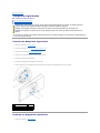
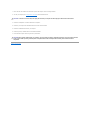
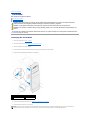
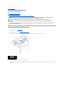
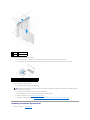
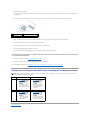
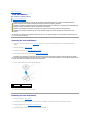
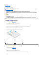
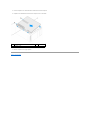
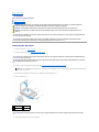
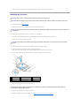
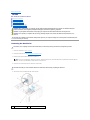
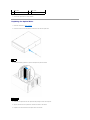
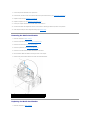
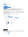
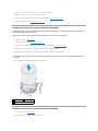
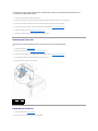
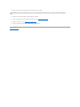
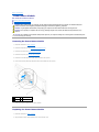
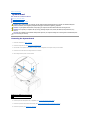
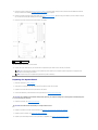
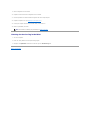
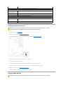
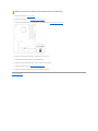
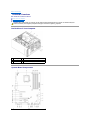
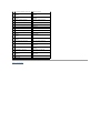
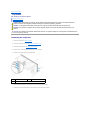
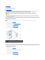
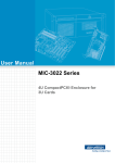
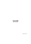
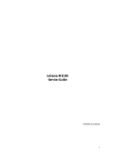
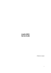
Dell™ Studio XPS™ 9100 Service Manual Before You Begin
Technical Overview
Computer Cover
Memory Module(s)
Front Bezel
Badge Back-Light Module
PCI and PCI Express Cards
Front USB 3.0 Assembly
Drives
Top Cover
I/O Panel
Power Button Module
Fans
Processor
Coin-Cell Battery
Power Supply
System Board
System Setup
Flashing the BIOS
Notes, Cautions, and Warnings
NOTE: A NOTE indicates important information that helps you make better use of your computer.
CAUTION: A CAUTION indicates either potential damage to hardware or loss of data and tells you how to avoid the problem.
WARNING: A WARNING indicates a potential for property damage, personal injury, or death.
Information in this document is subject to change without notice.
© 2010 Dell Inc. All rights reserved.
Reproduction of these materials in any manner whatsoever without the written permission of Dell Inc. is strictly forbidden.
Trademarks used in this text: Dell, the DELL logo, and Studio XPS are trademarks of Dell Inc.; Microsoft, Windows, and the Windows start button logo are either trademarks or
registered trademarks of Microsoft Corporation in the United States and/or other countries.
Other trademarks and trade names may be used in this document to refer to either the entities claiming the marks and names or their products. Dell Inc. disclaims any
proprietary interest in trademarks and trade names other than its own.
June 2010 Rev. A00
Regulatory model: DCRM
Back to Contents Page
Badge Back-Light Module
Dell™ Studio XPS™ 9100 Service Manual Removing the Badge Back-Light Module
Replacing the Badge Back-Light Module
WARNING: Before working inside your computer, read the safety information that shipped with your computer. For additional safety best
practices information, see the Regulatory Compliance Homepage at www.dell.com/regulatory_compliance.
WARNING: To guard against electrical shock, always unplug your computer from the electrical outlet before removing the cover.
WARNING: Do not operate your computer with any cover(s) (including computer covers, bezels, filler brackets, front-panel inserts, etc.)
removed.
CAUTION: Only a certified service technician should perform repairs on your computer. Damage due to servicing that is not authorized by Dell™ is not covered by your warranty.
Removing the Badge Back-Light Module
1.
Follow the instructions in Before You Begin.
2.
Remove the computer cover (see Removing the Computer Cover).
3.
Remove the front bezel (see Removing the Front Bezel).
4.
Remove the two screws that secure the hinge to the front bezel.
5.
Pull the hinge away from the front bezel.
6.
Remove the badge back-light cable from the securing tabs.
7.
Press the tabs away from the badge back-light module and pull the badge back-light module away from the front bezel.
1 badge back-light module 2 tabs (3)
3 badge back-light cable
4 screws (2)
5 hinge
Replacing the Badge Back-Light Module
1.
Follow the instructions in Before You Begin.
2.
Insert the badge back-light module into the slot on the front bezel.
3.
Press the badge back-light module down until it snaps into place.
4.
Route the badge back-light cable through the securing tabs.
5.
Align the screw holes on the hinge with the screw holes on the front bezel.
6.
Replace the two screws that secure the hinge to the front bezel.
7.
Replace the front bezel (see Replacing the Front Bezel).
8.
Replace the computer cover (see Replacing the Computer Cover).
Back to Contents Page
Back to Contents Page
Before You Begin
Dell™ Studio XPS™ 9100 Service Manual Technical Specifications
Recommended Tools
Turning Off Your Computer
Safety Instructions
This manual provides instructions for removing and installing the components in your computer. Unless otherwise noted, each procedure assumes that the
following conditions exist:
l
You have performed the steps in Turning Off Your Computer and Safety Instructions.
l
You have read the safety information that shipped with your computer.
l
A component can be replaced or—if purchased separately—installed by performing the removal procedure in reverse order.
Technical Specifications
For information on technical specifications of your computer, see the Setup Guide at support.dell.com/manuals.
Recommended Tools
The instructions in this document may require the following tools:
l
Small flat-blade screwdriver
l
Small Phillips screwdriver
l
BIOS executable update program available at support.dell.com
Turning Off Your Computer
CAUTION: To avoid losing data, save and close all open files and exit all open programs before you turn off your computer.
1.
Save and close all open files and exit all open programs.
2.
Shut down your computer:
Click Start
3.
4.
, and click Shut Down.
The computer turns off after the operating system shutdown process is complete.
Ensure that the computer is turned off. If your computer did not automatically turn off when you shut down the operating system, press and hold the
power button until the computer turns off.
Safety Instructions
Use the following safety guidelines to help protect your computer from potential damage and to help ensure your own personal safety.
WARNING: Before working inside your computer, read the safety information that shipped with your computer. For additional safety best
practices information, see the Regulatory Compliance Homepage at www.dell.com/regulatory_compliance.
CAUTION: Only a certified service technician should perform repairs on your computer. Damage due to servicing that is not authorized by Dell™ is not covered by your warranty.
CAUTION: When you disconnect a cable, pull on its connector or on its pull-tab, not on the cable itself. Some cables have connectors with locking
tabs; if you are disconnecting this type of cable, press in on the locking tabs before you disconnect the cable. As you pull connectors apart, keep
them evenly aligned to avoid bending any connector pins. Also, before you connect a cable, ensure that both connectors are correctly oriented
and aligned.
CAUTION: To avoid damaging the computer, perform the following steps before you begin working inside the computer.
1.
Ensure that the work surface is flat and clean to prevent the computer cover from being scratched.
2.
Turn off your computer (see Turning Off Your Computer) and all attached devices.
CAUTION: To disconnect a network cable, first unplug the cable from your computer and then unplug the cable from the network device.
3.
Disconnect all telephone or network cables from the computer.
4.
Disconnect your computer and all attached devices from their electrical outlets.
5.
Disconnect all attached devices from your computer.
6.
Press and eject any installed cards from the Media Card Reader.
7.
Press and hold the power button to ground the system board.
CAUTION: Before touching anything inside your computer, ground yourself by touching an unpainted metal surface, such as the metal at the back
of the computer. While you work, periodically touch an unpainted metal surface to dissipate static electricity, which could harm internal
components.
Back to Contents Page
Back to Contents Page
Front Bezel
Dell™ Studio XPS™ 9100 Service Manual Removing the Front Bezel
Replacing the Front Bezel
WARNING: Before working inside your computer, read the safety information that shipped with your computer. For additional safety best
practices information, see the Regulatory Compliance Homepage at www.dell.com/regulatory_compliance.
WARNING: To guard against electrical shock, always unplug your computer from the electrical outlet before removing the cover.
WARNING: Do not operate your computer with any cover(s) (including computer covers, front bezels, filler brackets, front-panel inserts, etc.)
removed.
CAUTION: Only a certified service technician should perform repairs on your computer. Damage due to servicing that is not authorized by Dell™ is not covered by your warranty.
Removing the Front Bezel
1.
Follow the instructions in Before You Begin.
2.
Remove the computer cover (see Removing the Computer Cover).
3.
Place the computer in an upright position.
4.
Press and hold the front-bezel release clamp and pull the front bezel away from the computer.
5.
Disconnect the badge back-light cable from the front bezel.
1 front-bezel release clamp 2 badge back-light cable
3 front-bezel tabs
4 front bezel
6.
Remove the badge back-light module (see Removing the Badge Back- Light Module).
7.
Set aside the front bezel in a secure location.
NOTE: Make a note of your computer's Service Tag/Express Service Code located on a label under the FlexBay panel. You will need the Service
Tag/Express Service Code to identify your computer when you access the Dell Support website or contact technical support.
Replacing the Front Bezel
1.
Follow the instructions in Before You Begin.
2.
Replace the badge back-light module (see Replacing the Badge Back-Light Module).
3.
Align and insert the front bezel tabs into the slots on the chassis.
4.
Push the front bezel towards the computer until the front-bezel tabs snap into place.
5.
Replace the computer cover (see Replacing the Computer Cover).
Back to Contents Page
Back to Contents Page
Flashing the BIOS
Dell™ Studio XPS™ 9100 Service Manual The BIOS may require flashing when an update is available or when replacing the system board. To flash the BIOS:
1.
Turn on the computer.
2.
Go to support.dell.com/support/downloads.
3.
Locate the BIOS update file for your computer.
NOTE: The Service Tag for your computer is located on a label under the FlexBay panel on the front of your computer.
If you have your computer's Service Tag:
a.
Click Enter a Service Tag.
b.
Enter your computer's Service Tag in the Enter a service tag field, click Go, and proceed to step 4.
If you do not have your computer's Service Tag:
a.
Select the type of product in the Select Your Product Family list.
b.
Select the product brand in the Select Your Product Line list.
c.
Select the product model number in the Select Your Product Model list.
NOTE: If you have selected a different model and want to start over again, click Start Over on the top right of the menu.
d.
Click Confirm.
4.
A list of results appear on the screen. Click BIOS.
5.
Click Download Now to download the latest BIOS file. The File Download window appears.
6.
Click Save to save the file on your desktop. The file downloads to your desktop.
7.
8.
Click Close if the Download Complete window appears. The file icon appears on your desktop and is titled the same as the downloaded BIOS update
file.
Double-click the file icon on the desktop and follow the instructions that appear on the screen.
Back to Contents Page
Back to Contents Page
PCI and PCI Express Cards
Dell™ Studio XPS™ 9100 Service Manual Removing PCI and PCI Express Cards
Replacing PCI and PCI Express Cards
Configuring Your Computer After Removing or Installing PCI and PCI Express Cards
WARNING: Before working inside your computer, read the safety information that shipped with your computer. For additional safety best
practices information, see the Regulatory Compliance Homepage at www.dell.com/regulatory_compliance.
WARNING: To guard against electrical shock, always unplug your computer from the electrical outlet before removing the cover.
WARNING: Do not operate your computer with any cover(s) (including computer covers, bezels, filler brackets, front-panel inserts, etc.)
removed.
CAUTION: Only a certified service technician should perform repairs on your computer. Damage due to servicing that is not authorized by Dell™ is not covered by your warranty.
Removing PCI and PCI Express Cards
1.
Follow the instructions in Before You Begin.
2.
Remove the computer cover (see Removing the Computer Cover).
3.
Push the tab on the expansion card retainer to release it from the alignment bar and pivot it away from the chassis.
1 alignment bar
2
tab
3 expansion card retainer
4.
5.
Disconnect any cables connected to the card, if applicable.
Press the tabs of the PCI support bracket and push the PCI support bracket to the back of the computer until it clicks into the slots on the back of the
computer.
1 slots (2) 2 PCI support bracket
3 tabs (2) 4 expansion card
6.
Remove the expansion card from the card slot:
l
For a PCI, PCI Express x1, or PCI Express x8 card, grasp the card by its top corners, and ease it out of its connector.
l
For a PCI Express x16 card, press the retention mechanism, grasp the card by its top corners, and then ease it out of its connector.
1 securing tab
2 retention mechanism
3 PCI Express x16 card 4 PCI Express x16 card connector
7.
If you are removing the card permanently:
a.
Install a filler bracket in the empty card-slot opening.
NOTE: Installing filler brackets over empty card-slot openings is necessary to maintain FCC certification of the computer. The brackets also keep
dust and dirt out of your computer.
b.
Push the PCI support bracket down until it clicks into the filler brackets.
c.
Pivot the expansion card retainer towards the alignment bar until it snaps into place.
d.
Replace the computer cover (see Replacing the Computer Cover).
e.
To complete the removal procedure, see Configuring Your Computer After Removing or Installing PCI and PCI Express Cards.
Replacing PCI and PCI Express Cards
1.
Follow the instructions in Before You Begin.
2.
Prepare the card for installation.
See the documentation that shipped with the card for information on configuring the card, making internal connections, or otherwise customizing it for
your computer.
3.
If you are installing a PCI Express card into the x16 card connector, position the card so the securing slot is aligned with the securing tab.
1 securing tab
2 securing slot
3 PCI Express x16 card 4 PCI Express x16 card connector
4.
Place the card in the connector on the system board and press down firmly. Ensure that the card is fully seated in the connector.
5.
Push the PCI support bracket down until it clicks into the filler brackets.
6.
Pivot the expansion card retainer towards the alignment bar until it snaps into place.
7.
Connect any cables that should be attached to the card.
See the documentation that shipped with the card for information about the card's cable connections.
CAUTION: Do not route card cables over or behind the cards. Cables routed over the cards can prevent the computer cover from closing properly
or cause damage to the equipment.
8.
Replace the computer cover (see Replacing the Computer Cover).
9.
Reconnect the computer and devices to electrical outlets, and then turn them on.
10.
To complete the installation, see Configuring Your Computer After Removing or Installing PCI and PCI Express Cards.
Configuring Your Computer After Removing or Installing PCI and PCI Express Cards
NOTE: For information on the location of external connectors, see the Setup Guide. For information on installing drivers and software for your card, see
the documentation that shipped with the card.
Sound
card
Installed
1.
2.
3.
Network
card
1.
2.
3.
1.
Enter system setup (see
System Setup)
Go to Onboard LAN
Controller and then
change the setting to
Disabled.
Connect the network
cable to the network
card's connector.
1.
Back to Contents Page
Removed
Enter system setup (see
System Setup)
Go to Onboard Audio
Controller and then
change the setting to
Disabled.
Connect the external
audio devices to the
sound card's connectors.
2.
3.
2.
3.
Enter system setup (see
System Setup)
Go to Onboard Audio
Controller and then
change the setting to
Enabled.
Connect the external
audio devices to the
computer's back panel
connectors.
Enter system setup (see
System Setup)
Go to Onboard LAN
Controller and then
change the setting to
Enabled.
Connect the network
cable to the integrated
network connector.
Back to Contents Page
Coin-Cell Battery
Dell™ Studio XPS™ 9100 Service Manual Removing the Coin-Cell Battery
Replacing the Coin-Cell Battery
WARNING: Before working inside your computer, read the safety information that shipped with your computer. For additional safety best
practices information, see the Regulatory Compliance Homepage at www.dell.com/regulatory_compliance.
WARNING: A new battery can explode if it is incorrectly installed. Replace the battery only with the same or equivalent type recommended by the
manufacturer. Discard used batteries according to the manufacturer's instructions.
WARNING: To guard against electrical shock, always unplug your computer from the electrical outlet before removing the cover.
WARNING: Do not operate your computer with any cover(s) (including computer covers, bezels, filler brackets, front-panel inserts, etc.)
removed.
CAUTION: Only a certified service technician should perform repairs on your computer. Damage due to servicing that is not authorized by Dell™ is not covered by your warranty.
Removing the Coin-Cell Battery
1.
Record all the screens in system setup (see System Setup) so that you can restore the correct settings after the new coin-cell battery has been
installed.
2.
Follow the instructions in Before You Begin.
3.
Remove the computer cover (see Removing the Computer Cover).
4.
Locate the battery socket on the system board (see System Board Components).
CAUTION: If you pry the battery out of its socket with a blunt object, be careful not to touch the system board with the object. Ensure that the
object is inserted between the battery and the socket before you attempt to pry out the battery. Otherwise, you may damage the system board by
prying off the socket or by breaking circuit traces on the system board.
5.
Press the battery-release lever to remove the coin-cell battery.
1 coin-cell battery 2 battery-release lever
3 battery socket
6.
Set aside the coin-cell battery in a secure location.
Replacing the Coin-Cell Battery
1.
Follow the instructions in Before You Begin
2.
Insert the new coin-cell battery (CR2032) into the socket with the side labeled "+" facing up, and press the coin-cell battery into place.
3.
Replace the computer cover (see Replacing the Computer Cover).
4.
Connect your computer and devices to electrical outlets, and then turn them on.
5.
Enter system setup (see System Setup) and restore the settings you recorded in step 1.
Back to Contents Page
Back to Contents Page
Computer Cover
Dell™ Studio XPS™ 9100 Service Manual Removing the Computer Cover
Replacing the Computer Cover
WARNING: Before working inside your computer, read the safety information that shipped with your computer. For additional safety best
practices information, see the Regulatory Compliance Homepage at www.dell.com/regulatory_compliance.
WARNING: To guard against likelihood of electric shock, laceration by moving fan blades, or other unexpected injuries, always unplug your
computer from the electrical outlet before removing the cover.
WARNING: Do not operate your computer with any cover(s) (including computer covers, bezels, filler brackets, front-panel inserts, etc.)
removed.
CAUTION: Only a certified service technician should perform repairs on your computer. Damage due to servicing that is not authorized by Dell™ is not covered by your warranty.
CAUTION: Ensure that sufficient space exists to support the computer with the cover removed—at least 30 cm (1 ft.) of desk top space.
Removing the Computer Cover
1.
Follow the instructions in Before You Begin.
2.
Lay the computer on its side with the computer cover facing up.
3.
Unlock and remove the security cable, if applicable.
4.
Remove the two thumbscrews that secure the computer cover to the chassis, using a screw driver, if necessary.
5.
Release the computer cover by sliding it away from the front of the computer.
6.
Lift the cover away from the computer and set it aside in a secure location.
1
thumbscrews (2)
2
computer cover
Replacing the Computer Cover
1.
Follow the instructions in Before You Begin.
2.
Connect all the cables and fold the cables out of the way.
3.
Ensure that no tools or extra parts are left inside the computer.
4.
Align the slots at the bottom of the computer cover with the tabs located along the edge of the chassis.
5.
Press the computer cover down and slide it towards the front of the computer.
6.
Replace the two thumbscrews that secure the computer cover to the chassis.
1
thumbscrews (2)
3
computer cover
7.
Place the computer in an upright position.
Back to Contents Page
2
slots
Back to Contents Page
Processor
Dell™ Studio XPS™ 9100 Service Manual Removing the Processor
Replacing the Processor
WARNING: Before working inside your computer, read the safety information that shipped with your computer. For additional safety best
practices information, see the Regulatory Compliance Homepage at www.dell.com/regulatory_compliance.
WARNING: To guard against electrical shock, always unplug your computer from the electrical outlet before removing the cover.
WARNING: Do not operate your computer with any cover(s) (including computer covers, bezels, filler brackets, front-panel inserts, etc.)
removed.
CAUTION: Only a certified service technician should perform repairs on your computer. Damage due to servicing that is not authorized by Dell™ is not covered by your warranty.
CAUTION: Do not perform the following steps unless you are familiar with hardware removal and replacement. Performing these steps
incorrectly could damage your system board. To contact Dell for technical service, see the Setup Guide.
Removing the Processor
1.
Follow the instructions in Before You Begin.
2.
Remove the computer cover (see Removing the Computer Cover).
CAUTION: Only a certified service technician should perform repairs on your computer. Damage due to servicing that is not authorized by Dell™ is not covered by your warranty.
CAUTION: Despite having a plastic shield, the processor fan and heat sink assembly may be very hot during normal operation. Ensure that it has
had sufficient time to cool before you touch it.
3.
Remove the processor fan and heat sink assembly (see Removing the Processor Fan and Heat Sink Assembly).
NOTE: Unless a new processor fan and heat sink is required for the new processor, reuse the original processor fan and heat sink assembly when
you replace the processor.
4.
Press and push the release lever down and out to release it from the tab that secures it.
5.
Open the processor cover.
1 processor cover 2 processor
3 socket
4 release lever
CAUTION: When removing the processor, do not touch any of the pins inside the socket or allow any objects to fall on the pins in the socket.
6.
Gently lift the processor to remove it from the socket.
Leave the release lever extended in the release position so that the socket is ready for the new processor.
Replacing the Processor
CAUTION: Ground yourself by touching an unpainted metal surface on the back of the computer.
CAUTION: When replacing the processor, do not touch any of the pins inside the socket or allow any objects to fall on the pins in the socket.
1.
Follow the instructions in Before You Begin.
2.
Unpack the new processor, being careful not to touch the underside of the processor. CAUTION: You must position the processor correctly in the socket to avoid permanent damage to the processor and the computer when you turn
on the computer.
3.
If the release lever on the socket is not fully extended, move it to that position.
4.
Orient the front and rear alignment-notches on the processor with the front and rear alignment-tabs on the socket.
5.
Align the pin-1 corners of the processor and socket.
CAUTION: To avoid damage, ensure that the processor aligns properly with the socket, and do not use excessive force when you install the
processor.
6.
7.
8.
Set the processor gently in the socket and ensure that the processor is positioned correctly.
When the processor is fully seated in the socket, close the processor cover.
Ensure that the tab on the processor cover is positioned underneath the center cover latch on the socket.
Pivot the socket release lever back towards the socket, and snap it into place to secure the processor.
1 front alignment notch 2 processor pin-1 indicator 3 rear alignment notch
4 processor cover
5 tab
6 processor
7 socket
8 center cover latch
9 release lever
9.
Clean the thermal grease from the bottom of the heat sink.
CAUTION: Ensure that you apply new thermal grease. New thermal grease is critical for ensuring adequate thermal bonding, which is a
requirement for optimal processor operation.
10.
Apply the new thermal grease to the top of the processor.
11.
Replace the processor fan and heat sink assembly (see Replacing the Processor Fan and Heat Sink Assembly).
CAUTION: Ensure that the processor fan and heat sink assembly is correctly seated and secure.
12.
Replace the computer cover (see Replacing the Computer Cover).
Back to Contents Page
Back to Contents Page
Drives
Dell™ Studio XPS™ 9100 Service Manual Removing the Hard Drive
Replacing the Hard Drive
Removing the Optical Drive
Replacing the Optical Drive
Removing the Media Card Reader
Replacing the Media Card Reader
WARNING: Before working inside your computer, read the safety information that shipped with your computer. For additional safety best
practices information, see the Regulatory Compliance Homepage at www.dell.com/regulatory_compliance.
WARNING: To guard against electrical shock, always unplug your computer from the electrical outlet before removing the cover.
WARNING: Do not operate your computer with any cover(s) (including computer covers, bezels, filler brackets, front-panel inserts, etc.)
removed.
CAUTION: Only a certified service technician should perform repairs on your computer. Damage due to servicing that is not authorized by Dell™ is not covered by your warranty.
Removing the Hard Drive
CAUTION: If you are replacing a hard drive that contains data you want to keep, back up your files before you begin this procedure.
1.
Follow the instructions in Before You Begin.
2.
Remove the computer cover (see Removing the Computer Cover).
3.
Disconnect the power and data cables from the hard drive.
NOTE: If you are not replacing the hard drive at this time, disconnect the other end of the data cable from the system board connector and set it
aside. You can use the data cable to install a hard drive at a later time.
4.
Remove the two screws that secure the hard drive to the chassis.
CAUTION: Ensure that you do not scratch the hard drive's circuit board, while removing or replacing the hard drive.
5.
1
Slide the hard drive out towards the back of the computer.
data cable
2
power cable
3
hard drive
6.
4
screws (2)
If removing the hard drive changes the drive configuration, ensure that you reflect these changes in the system setup (see System Setup).
Replacing the Hard Drive
1.
Follow the instructions in Before You Begin.
2.
Check the documentation that shipped with the drive to verify that it is configured for your computer.
3.
Slide the hard drive into the hard drive bay.
4.
Align the screw holes on the hard drive with the screw holes on the chassis.
5.
Replace the two screws that secure the hard drive to the chassis.
6.
Connect the power and data cables to the hard drive.
7.
If disconnected, connect the other end of the data cable to the system board connector (see System Board Components).
8.
Replace the computer cover (see Replacing the Computer Cover).
9.
Connect your computer and devices to electrical outlets, and then turn them on.
10.
See the documentation that shipped with the drive for instructions on installing any software required for drive operation.
11.
Check the System Setup for drive configuration changes (see System Setup).
Removing the Optical Drive
1.
Follow the instructions in Before You Begin.
2.
Remove the computer cover (see Removing the Computer Cover).
3.
Remove the front bezel (see Removing the Front Bezel).
4.
Disconnect the power and data cables from the optical drive.
NOTE: If you are not replacing the optical drive at this time, disconnect the other end of the data cable from the system board connector and set it
aside. You can use the data cable to install an optical drive at a later time.
5.
Remove the two screws that secure the optical drive to the chassis.
6.
Push and slide the optical drive out through the front of the computer.
1
data cable
2
power cable
3
optical drive
4
screws (2)
7.
Set aside the optical drive in a secure location.
Replacing the Optical Drive
1.
Follow the instructions in Before You Begin.
2.
Remove the screw from the old optical drive and insert it into the new optical drive.
1 screw
3.
To install a secondary optical drive, pull the metal plate away from the chassis.
1 metal plate
4.
Gently slide the optical drive into the optical drive bay through the front of the computer.
5.
Align the screw holes on the optical drive with the screw holes on the chassis.
6.
Replace the two screws that secure the optical drive to the chassis.
7.
Connect the power and data cables to the optical drive.
8.
If disconnected, connect the other end of the data cable to the system board connector (see System Board Components).
9.
Replace the front bezel (see Replacing the Front Bezel).
10.
Replace the computer cover (see Replacing the Computer Cover).
11.
Connect your computer and devices to electrical outlets, and turn them on.
12.
See the documentation that shipped with the drive for instructions on installing any software required for drive operation.
13.
Check the System Setup for drive configuration changes (see System Setup).
Removing the Media Card Reader
1.
Follow the instructions in Before You Begin.
2.
Remove the computer cover (see Removing the Computer Cover).
3.
Remove the front bezel (see Removing the Front Bezel).
4.
Remove the optical drive (see Removing the Optical Drive).
5.
Remove the screw that secures the Media Card Reader to the chassis.
6.
Push and slide the Media Card Reader out through the front of the computer.
7.
Disconnect the power and data cables from the back of the Media Card Reader.
1
screw
2
data cable
3
power cable
4
Media Card Reader
Replacing the Media Card Reader
1.
Follow the instructions in Before You Begin.
2.
Connect the power and data cables to the back of the Media Card Reader.
3.
Gently slide the Media Card Reader into the drive bay.
4.
Replace the screw that secures the Media Card Reader to the chassis.
5.
Replace the optical drive (see Replacing the Optical Drive).
6.
Replace the front bezel (see Replacing the Front Bezel).
7.
Replace the computer cover (see Replacing the Computer Cover).
8.
Connect your computer and devices to electrical outlets, and then turn them on.
Back to Contents Page
Back to Contents Page
Fans
Dell™ Studio XPS™ 9100 Service Manual Removing the Chassis Fan
Replacing the Chassis Fan
Removing the Processor Fan and Heat Sink Assembly
Replacing the Processor Fan and Heat Sink Assembly
Removing the Front Fan
Replacing the Front Fan
WARNING: Before working inside your computer, read the safety information that shipped with your computer. For additional safety best
practices information, see the Regulatory Compliance Homepage at www.dell.com/regulatory_compliance.
WARNING: To guard against electrical shock, always unplug your computer from the electrical outlet before removing the cover.
WARNING: Do not operate your computer with any cover(s) (including computer covers, bezels, filler brackets, front-panel inserts, etc.)
removed.
CAUTION: Only a certified service technician should perform repairs on your computer. Damage due to servicing that is not authorized by Dell™ is not covered by your warranty.
Removing the Chassis Fan
CAUTION: Do not touch the fan blades when you are removing the chassis fan, as this could damage the fan.
1.
Follow the instructions in Before You Begin.
2.
Remove the computer cover (see Removing the Computer Cover).
3.
Disconnect the chassis fan cable from the system board connector SYS_FAN (see System Board Components).
4.
Remove the four screws that secure the chassis fan to the chassis.
5.
Slide and lift the chassis fan away from the computer as shown in the illustration.
1 chassis fan 2 screws (4)
3 chassis fan cable
Replacing the Chassis Fan
1.
Follow the instructions in Before You Begin.
2.
Align the screw holes on the chassis fan with the screw holes on the chassis.
3.
Replace the four screws that secure the chassis fan to the chassis.
4.
Connect the chassis fan cable to the system board connector SYS_FAN (see System Board Components).
5.
Replace the computer cover (see Replacing the Computer Cover).
Removing the Processor Fan and Heat Sink Assembly
WARNING: Despite having a plastic shield, the processor fan and heat sink assembly may be very hot during normal operation. Ensure that it has
had sufficient time to cool before you touch it.
CAUTION: The processor fan and heat sink assembly is a single unit. Do not try to remove the fan separately.
1.
Follow the instructions in Before You Begin.
2.
Remove the computer cover (see Removing the Computer Cover).
3.
Disconnect the processor fan cable from the system board connector CPU_FAN (see System Board Components).
4.
Carefully move away any cables that are routed over the processor fan and heat sink assembly.
5.
Loosen the four captive screws that secure the processor fan and heat sink assembly to the system board.
CAUTION: When you remove the processor fan and heat sink assembly, lay it upside down or on its side to avoid damaging the heat sink thermal
interface.
6.
Lift the processor fan and heat sink assembly out of the computer.
1 captive screws (4) 2 processor fan cable
3 processor fan and heat sink assembly
Replacing the Processor Fan and Heat Sink Assembly
1.
Follow the instructions in Before You Begin
2.
Clean the thermal grease from the bottom of the heat sink.
CAUTION: Ensure that you apply new thermal grease. New thermal grease is critical for ensuring adequate thermal bonding, which is a
requirement for optimal processor operation.
3.
Apply new thermal grease to the top of the processor.
4.
Align the four captive screws on the processor fan and heat sink assembly with the screw holes on the system board.
5.
Tighten the four captive screws that secure the processor fan and heat sink assembly to the system board.
6.
Connect the processor fan cable to the system board connector CPU_FAN (see System Board Components).
7.
Replace the computer cover (see Replacing the Computer Cover).
8.
Connect your computer and devices to electrical outlets, and turn them on.
Removing the Front Fan
CAUTION: Do not touch the fan blades when you are removing the front fan, as this could damage the fan.
1.
Follow the instructions in Before You Begin.
2.
Remove the computer cover (see Removing the Computer Cover).
3.
Disconnect the front fan cable from the system board connector PWR_FAN (see System Board Components).
4.
Press the tabs and pull the front fan towards the back of the computer.
5.
Lift the fan out of the computer, and set it aside.
1 front fan 2 tabs (2)
3 front fan cable
Replacing the Front Fan
1.
Follow the instructions in Before You Begin.
2.
Align the tabs on the front fan with the slots on the chassis.
3.
Push the front fan towards the front of the computer, until the tabs snap into place.
4.
Connect the front fan cable to the system board connector PWR_FAN (see System Board Components).
5.
Replace the computer cover (see Replacing the Computer Cover).
Back to Contents Page
Back to Contents Page
Memory Module(s)
Dell™ Studio XPS™ 9100 Service Manual Removing the Memory Module(s)
Replacing the Memory Module(s)
WARNING: Before working inside your computer, read the safety information that shipped with your computer. For additional safety best
practices information, see the Regulatory Compliance Homepage at www.dell.com/regulatory_compliance.
WARNING: To guard against electrical shock, always unplug your computer from the electrical outlet before removing the cover.
WARNING: Do not operate your computer with any cover(s) (including computer covers, bezels, filler brackets, front-panel inserts, etc.)
removed.
CAUTION: Only a certified service technician should perform repairs on your computer. Damage due to servicing that is not authorized by Dell™ is not covered by your warranty.
Removing the Memory Module(s)
1.
Follow the instructions in Before You Begin.
2.
Remove the computer cover (see Removing the Computer Cover).
3.
Locate the memory module(s) on the system board (see System Board Components).
4.
Press out the securing clip at each end of the memory module connector.
1
memory module connector
5.
2
securing clip
Grasp the memory module and pull it upwards.
If the memory module is difficult to remove, gently ease the memory module back and forth to remove it from the connector.
Replacing the Memory Module(s)
1.
Follow the instructions in Before You Begin.
2.
Press out the securing clip at each end of the memory module connector.
CAUTION: Only a certified service technician should perform repairs on your computer. Damage due to servicing that is not authorized by Dell™ is not covered by your warranty.
CAUTION: Do not install ECC memory modules.
CAUTION: If you remove your original memory module(s) from the computer during a memory upgrade, keep them separate from any new
memory module(s) that you may have, even if you purchased the new memory module(s) from Dell™. If possible, do not pair an original memory module with a new memory module. Otherwise, your computer may not start properly. The recommended memory configurations are: matched
memory module(s) installed in DIMM connectors 4, 5, and 6 and another matched memory module(s) installed in DIMM connectors 1, 2, and 3.
1 matched memory modules in
connectors DIMM4, DIMM5, and
DIMM6 (pink connectors)
3.
2 matched memory modules in
connectors DIMM1, DIMM2, and
DIMM3 (blue connectors)
Align the notch on the bottom of the memory module with the tab in the connector.
1
cutouts (2)
2
tab
3
notch
4
memory module
CAUTION: To avoid damage to the memory module, press the memory module straight down into the connector while you apply equal force to
each end of the memory module.
4.
Insert the memory module into the connector until the memory module snaps into position.
If you insert the memory module correctly, the securing clips snap into the cutouts at each end of the memory module.
1
cutouts (2)
2
securing clip (snapped in position)
5.
Replace the computer cover (see Replacing the Computer Cover).
6.
Connect your computer and devices to electrical outlets, and then turn them on.
If the message appears stating that memory size has changed, press <F1> to continue.
7.
Log on to your computer.
8.
Click Start
, right-click Computer, and click Properties.
9.
To verify that the memory is installed correctly, check the amount of memory (RAM) listed.
Back to Contents Page
Back to Contents Page
Power Supply
Dell™ Studio XPS™ 9100 Service Manual Removing the Power Supply
Replacing the Power Supply
WARNING: Before working inside your computer, read the safety information that shipped with your computer. For additional safety best
practices information, see the Regulatory Compliance Homepage at www.dell.com/regulatory_compliance.
WARNING: To guard against electrical shock, always unplug your computer from the electrical outlet before removing the cover.
WARNING: Do not operate your computer with any cover(s) (including computer covers, bezels, filler brackets, front-panel inserts, etc.)
removed.
CAUTION: Only a certified service technician should perform repairs on your computer. Damage due to servicing that is not authorized by Dell™ is not covered by your warranty.
Removing the Power Supply
1.
Follow the instructions in Before You Begin.
2.
Remove the computer cover (see Removing the Computer Cover).
3.
Disconnect the DC power cables from the system board and the drives (see System Board Components).
4.
Release all cables from the securing clip on the bottom of the power supply.
5.
Remove the four screws that secure the power supply to the chassis.
6.
Press the tab and slide the power supply towards the front of the computer.
7.
Lift the power supply away from the chassis.
1 tab 2 power supply
3 screws (4)
Replacing the Power Supply
1.
Follow the instructions in Before You Begin.
2.
Slide the power supply towards the back of the chassis.
3.
Align the screw holes on the power supply with the screw holes on the chassis.
WARNING: Failure to replace and tighten all screws may cause electrical shock as these screws are a key part of the system grounding.
4.
Replace the four screws that secure the power supply to the chassis.
5.
Connect the DC power cables to the system board and drives (see System Board Components).
6.
Replace the computer cover (see Replacing the Computer Cover).
7.
Connect your computer and devices to electrical outlets, and turn them on.
Back to Contents Page
Back to Contents Page
Power Button Module
Dell™ Studio XPS™ 9100 Service Manual Removing the Power Button Module
Replacing the Power Button Module
WARNING: Before working inside your computer, read the safety information that shipped with your computer. For additional safety best
practices information, see the Regulatory Compliance Homepage at www.dell.com/regulatory_compliance.
WARNING: To guard against electrical shock, always unplug your computer from the electrical outlet before removing the cover.
WARNING: Do not operate your computer with any cover(s) (including computer covers, bezels, filler brackets, front-panel inserts, etc.)
removed.
CAUTION: Only a certified service technician should perform repairs on your computer. Damage due to servicing that is not authorized by Dell™ is not covered by your warranty.
Removing the Power Button Module
1.
Follow the instructions in Before You Begin.
2.
Remove the computer cover (see Removing the Computer Cover).
3.
Remove the front bezel (see Removing the Front Bezel).
4.
Remove the top cover (see Removing the Top Cover).
5.
Remove the screw that secures the power button module to the top cover.
6.
Press out the securing tab and pull the power button module away from the top cover.
1 screw
2 power button module
3 securing tab 4 top cover
7.
Set the power button module aside in a secure location.
Replacing the Power Button Module
1.
Follow the instructions in Before You Begin.
2.
Align and push the power button module into the slot on the top cover.
3.
Replace the screw that secures the power button module to the top cover.
4.
Replace the top cover (see Replacing the Top Cover).
5.
Replace the front bezel (see Replacing the Front Bezel).
6.
Replace the computer cover (see Replacing the Computer Cover).
7.
Connect your computer and devices to electrical outlets, and turn them on.
Back to Contents Page
Back to Contents Page
System Board
Dell™ Studio XPS™ 9100 Service Manual Removing the System Board
Replacing the System Board
Entering the Service Tag in the BIOS
WARNING: Before working inside your computer, read the safety information that shipped with your computer. For additional safety best
practices information, see the Regulatory Compliance Homepage at www.dell.com/regulatory_compliance.
WARNING: To guard against electrical shock, always unplug your computer from the electrical outlet before removing the cover.
WARNING: Do not operate your computer with any cover(s) (including computer covers, bezels, filler brackets, front-panel inserts, etc.)
removed.
CAUTION: Only a certified service technician should perform repairs on your computer. Damage due to servicing that is not authorized by Dell™ is not covered by your warranty.
Removing the System Board
1.
Follow the instructions in Before You Begin.
2.
Remove the computer cover (see Removing the Computer Cover).
3.
Push the tab on the expansion card retainer to release it from the alignment bar and pivot it away from the chassis.
4.
Remove the screw that secures the alignment bar to the chassis.
5.
Lift the alignment bar up and out of the chassis.
1 alignment bar 2 expansion card retainer
3 screw
6.
Remove any PCI and PCI Express cards, if applicable (see Removing PCI and PCI Express Cards).
7.
Remove the processor fan and heat sink assembly (see Removing the Processor Fan and Heat Sink Assembly).
8.
Remove the processor (see Removing the Processor).
9.
10.
11.
Remove the memory modules (see Removing the Memory Module(s)) and record which memory module is removed from each DIMM slot so that the
memory modules can be installed in the same slot after the system board is replaced.
Disconnect all cables connected to the system board (see System Board Components). Note the routing of all cables as you remove them so that you
can re-route them correctly after installing the new system board.
Remove the ten screws that secure the system board to the chassis.
1 screws (10) 2 system board
12.
Lift the system board up and out of the chassis.
13.
Compare the system board that you just removed with the replacement system board to ensure that they are identical.
NOTE: Some components and connectors on the replacement system board may be in different locations compared to the components and
connectors on the existing system board.
NOTE: Jumper settings on the replacement system board is preset at the factory.
Replacing the System Board
1.
Follow the instructions in Before You Begin.
2.
Gently place the system board into the chassis and slide it towards the back of the computer.
3.
Replace the ten screws that secure the system board to the chassis.
4.
Connect the cables that you disconnected from the system board (see System Board Components).
CAUTION: Only a certified service technician should perform repairs on your computer. Damage due to servicing that is not authorized by Dell™ is not covered by your warranty.
5.
Replace the processor (see Replacing the Processor).
CAUTION: Ensure that the heat sink assembly is correctly seated and secure.
6.
Replace the processor fan and the heat sink assembly (see Replacing the Processor Fan and Heat Sink Assembly).
7.
Replace the memory modules (see Replacing the Memory Module(s)).
8.
Replace any PCI and PCI Express cards on the system board, if applicable (see Replacing PCI and PCI Express Cards).
9.
Place the alignment bar in the chassis.
10.
Replace the screw that secures the alignment bar to the chassis.
11.
Pivot the expansion card retainer towards the alignment bar until it snaps into place.
12.
Replace the computer cover (see Replacing the Computer Cover).
13.
Connect your computer and devices to electrical outlets, and turn them on.
14.
Flash the system BIOS, as needed.
NOTE: For information on flashing the system BIOS, see Flashing the BIOS.
Entering the Service Tag in the BIOS
1.
Turn on the computer.
2.
Press <F2> during POST to enter the System Setup program.
3.
Navigate to the System Info tab and enter the Service Tag in the Set Service Tag field.
Back to Contents Page
Back to Contents Page
System Setup
Dell™ Studio XPS™ 9100 Service Manual Overview
Clearing Forgotten Passwords
Clearing CMOS Settings
Overview
Use system setup to:
l
Change the system configuration information after you add, change, or remove any hardware in your computer
l
Set or change a user-selectable option such as the user password
l
Read the current amount of memory or set the type of hard drive installed
CAUTION: Only a certified service technician should perform repairs on your computer. Damage due to servicing that is not authorized by Dell™ is not covered by your warranty.
CAUTION: Unless you are an expert computer user, do not change the settings for this program. Certain changes can make your computer work
incorrectly.
NOTE: Before you change system setup, it is recommended that you write down the system setup screen information for future reference.
Entering System Setup
1.
Turn on (or restart) your computer.
2.
When the DELL™ logo is displayed, watch for the F2 prompt to appear and then press <F2> immediately. NOTE: The F2 prompt indicates that the keyboard has initialized. This prompt can appear very quickly, so you must watch for it to display, and
then press <F2>. If you press <F2> before you are prompted, this keystroke will be lost. If you wait too long and the operating system logo
appears, continue to wait until you see the Microsoft® Windows® desktop. Then, shut down your computer (see Turning Off Your Computer) and
try again.
System Setup Screens
The system setup screen displays the current or changeable configuration information for your computer. Information on the screen is divided into three areas:
the options list, active options field, and key functions.
Menu — Appears on top of the System Setup window. This field provides a menu to access the System Setup options. Press the up- and down-arrow keys to
navigate. As a Menu option is highlighted, the Options List, lists the options that define the hardware installed on you computer.
Options List — Appears on the left side of the
System Setup window. The field lists features
that define the configuration of your computer,
including installed hardware, power
conservation, and security features.
Scroll up and down the list using the up- and
down-arrow keys. As an option is highlighted,
the Options Field displays the option's current
and available settings.
Options Field — Appears on the right side of Options List and
contains information about each option listed in the Options List. In
this field you can view information about your computer and make
changes to your current settings. Press <Enter> to make changes to
your current settings. Press <ESC> to return to the Options List.
NOTE: Not all settings listed in the Options Field are changeable.
Key Functions — Appears below the Options Field and lists keys and their functions within the active system setup field.
System Setup Options
NOTE: The items listed in this table may vary depending on your computer and installed devices.
System Info
BIOS Info
Displays the BIOS version number and date information
System
Displays the system model number
Service Tag
Displays the service tag of the computer
Asset Tag
Displays the asset tag of the computer if present
Processor Type
Displays the processor type
Help — Appears on the right side
of the System Setup window and
contains help information about
the option selected in Options
List.
Processor Cache L1
Displays the processor L1 cache size
Processor Cache L2
Displays the processor L2 cache size
Processor Cache L3
Displays the processor L3 cache size
Memory Installed
Indicates the amount of installed memory in MB
Memory Available
Indicates the amount of memory available in MB
Memory Speed
Indicates the memory speed in MHz
Memory Technology
Indicates the memory technology; DDR3
Standard CMOS Features
System Time
Displays the current time in hh:mm:ss format
System Date
Displays the current date in mm:dd:yy format
SATA0
Displays the SATA0 drive integrated in the computer
SATA1
Displays the SATA1 drive integrated in the computer
SATA2
Displays the SATA2 drive integrated in the computer
SATA3
Displays the SATA3 drive integrated in the computer
SATA4
Displays the SATA4 drive integrated in the computer
eSATA
Displays the eSATA drive connected to the computer
Advanced BIOS Features
CPU Feature
l
Secure Virtual Machine Mode — Enabled or Disabled (Enabled by default)
USB Device Setting
l
USB Controller — Enabled or Disabled (Enabled by default)
USB Operation Mode — High Speed; Full/Low Speed (High Speed by default)
l
Advanced Chipset Features
Onboard Audio Controller
Enabled or Disabled (Enabled by default)
SATA Mode
AHCI/RAID (AHCI by default)
Onboard LAN Controller
Enabled or Disabled (Enabled by default)
Onboard LAN Boot ROM
Enabled or Disabled (Disabled by default)
Onboard 1394 Controller
Enabled or Disabled (Enabled by default)
Boot Device Configuration
Boot Settings Configuration Configures the settings during system boot
Hard Disk Boot Priority
Sets the hard drive boot priority. The items displayed are dynamically updated according to the hard drives detected
CD/DVD Drives Boot Priority Sets the CD/DVD drive boot priority. The items displayed are dynamically updated according to the drives detected
1st Boot Device
Specifies the boot sequence from the available devices
Removable; CD/DVD; Hard Drive; Disabled (Removable by default)
2nd Boot Device
Specifies the boot sequence from the available devices
Removable; CD/DVD; Hard Drive; Disabled (CD/DVD by default)
3rd Boot Device
Specifies the boot sequence from the available devices
Removable; CD/DVD; Hard Drive; Disabled (Hard Drive by default).
Boot Other Device
No; Yes (Yes by default)
Power Management Setup
ACPI Suspend Type
Specifies the ACPI suspend type. The default is S3
Remote Wake Up
This option turns on the computer when you try to access the computer through the LAN (Enabled by default)
AC Recovery
Specifies the behavior of the computer after recovering from a power loss (Off by default)
l
l
l
On — The computer turns on after it recovers from a power failure
Off — The computer remains off
Last — The computer returns to the power state it was in before the power failure
Auto Power On
Enables you to set an alarm to turn on the computer automatically
BIOS Security Features
Supervisor Password
Status of supervisor installed
User Password
Status of user installed
Set Supervisor Password
Allows to set the desired supervisor password
Exit
Exit Options
Provides options to Load Default, Save and Exit Setup, and Exit Without Saving
Clearing Forgotten Passwords
WARNING: Before you begin any of the instructions in this section, follow the safety instructions that shipped with your computer.
WARNING: The computer must be disconnected from the electrical outlet to clear the CMOS setting.
1.
Follow the instructions in Before You Begin.
2.
Remove the computer cover (see Removing the Computer Cover).
3.
Locate the 3-pin password reset jumper (CLR_PWD) on the system board (see System Board Components).
4.
Remove the 2-pin jumper plug from pins 1 and 2 and fix it on pins 2 and 3.
5.
Turn on the computer to clear the password.
6.
Turn off the computer and disconnect your computer and all attached devices from their electrical outlets.
7.
Remove the 2-pin jumper plug from pins 2 and 3 and replace it on pins 1 and 2 to enable the password feature.
8.
Replace the computer cover (see Replacing the Computer Cover).
9.
Connect your computer and devices to electrical outlets, and turn them on.
Clearing CMOS Settings
WARNING: Before you begin any of the instructions in this section, follow the safety instructions that shipped with your computer.
WARNING: The computer must be disconnected from the electrical outlet to clear the CMOS setting.
1.
Follow the instructions in Before You Begin.
2.
Remove the computer cover (see Removing the Computer Cover).
3.
Locate the 3-pin CMOS reset jumper (CLR_CMOS) on the system board (see System Board Components).
4.
Remove the 2-pin jumper plug from pins 2 and 3 and fix it on pins 1 and 2.
5.
Wait for approximately five seconds to clear the CMOS setting.
6.
Remove the 2-pin jumper plug from pins 1 and 2 and replace it on pins 2 and 3.
7.
Replace the computer cover (see Removing the Computer Cover).
8.
Connect your computer and devices to electrical outlets, and turn them on.
Back to Contents Page
Back to Contents Page
Technical Overview
Dell™ Studio XPS™ 9100 Service Manual Inside View of Your Computer
System Board Components
WARNING: Before working inside your computer, read the safety information that shipped with your computer. For additional safety best
practices information, see the Regulatory Compliance Homepage at www.dell.com/regulatory_compliance.
Inside View of Your Computer
1
power supply
2
processor fan and heat sink assembly
3
hard drive
4
Media Card Reader
5
optical drive
6
front USB 3.0 assembly (optional)
System Board Components
1
12 V power connector (ATX_12V) 2
processor socket
3
memory module connector
(DIMM4)
4
memory module connector
(DIMM1)
5
memory module connector
(DIMM5)
6
memory module connector
(DIMM2)
7
memory module connector
(DIMM6)
8
memory module connector
(DIMM3)
9
main power connector (ATX1)
10 SATA connector (S_SATA1)
11 SATA connector (S_SATA2)
12 front panel USB connector
(FUSB_4)
13 front panel USB connector
(FUSB_5)
14 front panel connector (F_PANEL)
15 SATA connector (S_SATA3)
16 front fan connector (PWR_FAN)
17 front panel USB connector
(FUSB_3)
18 password reset jumper
(CLR_PWD)
19 front panel USB connector
(FUSB_1)
20 CMOS reset jumper (CLR_CMOS)
21 top panel USB connector
(FUSB_2)
22 S/PDIF connector (SPDIF_IO)
23 badge back-light connector
(JPWR)
24 top panel audio connector
(F_AUDIO)
25 PCI card slot (PCI_1)
26 PCI Express x1 card slot
(PCIE1X3)
27 battery socket (BATTERY)
28 PCI Express x16 card slot
(PCIE16_1)
29 PCI Express x1 card slot
(PCIE1X2)
30 PCI Express x1 card slot
(PCIE1X1)
31 PCI Express x8 card slot
(PCIE8_2)
32 chassis fan connector
(SYS_FAN)
33 processor fan connector
(CPU_FAN)
Back to Contents Page
Back to Contents Page
Top Cover
Dell™ Studio XPS™ 9100 Service Manual Removing the Top Cover
Replacing the Top Cover
WARNING: Before working inside your computer, read the safety information that shipped with your computer. For additional safety best
practices information, see the Regulatory Compliance Homepage at www.dell.com/regulatory_compliance.
WARNING: To guard against electrical shock, always unplug your computer from the electrical outlet before removing the cover.
WARNING: Do not operate your computer with any cover(s) (including computer covers, bezels, filler brackets, front-panel inserts, etc.)
removed.
CAUTION: Only a certified service technician should perform repairs on your computer. Damage due to servicing that is not authorized by Dell™ is not covered by your warranty.
Removing the Top Cover
1.
Follow the instructions in Before You Begin.
2.
Remove the computer cover (see Removing the Computer Cover).
3.
Remove the front bezel (see Removing the Front Bezel).
4.
Remove the two screws that secure the top cover to the computer.
5.
Disconnect the cables connected to the I/O panel.
1
I/O panel
3
top cover
2
screws (2)
6.
While pulling the release tab, slide and pull the top cover away from the chassis.
7.
Disconnect the power button cable from the connector on the power button module.
1
release tab
3
power button module
2
power button cable
8.
Remove the I/O panel (see Removing the I/O Panel).
9.
Remove the power button module (see Removing the Power Button Module).
10.
Set the top cover aside in a secure location.
Replacing the Top Cover
1.
Follow the instructions in Before You Begin.
2.
Replace the power button module (see Replacing the Power Button Module).
3.
Replace the I/O panel (see Replacing the I/O Panel).
4.
Connect the power button cable to the connector on the power button module.
5.
Align the tabs in the top cover with the slots in the chassis.
6.
Press and slide the top cover towards the back of the computer, until it clicks into place.
7.
Connect the cables that you disconnected from the I/O panel.
8.
Replace the two screws that secure the top cover to the chassis.
9.
Replace the front bezel (see Replacing the Front Bezel).
10.
Replace the computer cover (see Replacing the Computer Cover).
Back to Contents Page
Back to Contents Page
I/O Panel
Dell™ Studio XPS™ 9100 Service Manual Removing the I/O Panel
Replacing the I/O Panel
WARNING: Before working inside your computer, read the safety information that shipped with your computer. For additional safety best
practices information, see the Regulatory Compliance Homepage at www.dell.com/regulatory_compliance.
WARNING: To guard against electrical shock, always unplug your computer from the electrical outlet before removing the cover.
WARNING: Do not operate your computer with any cover(s) (including computer covers, bezels, filler brackets, front-panel inserts, etc.)
removed.
CAUTION: Only a certified service technician should perform repairs on your computer. Damage due to servicing that is not authorized by Dell™ is not covered by your warranty.
Removing the I/O Panel
NOTE: Make note of the routing of all cables as you remove them so that you can re-route them correctly when installing the new I/O panel.
1.
Follow the instructions in Before You Begin.
2.
Remove the computer cover (see Removing the Computer Cover).
3.
Remove the front bezel (see Removing the Front Bezel).
4.
Remove the top cover (see Removing the Top Cover).
5.
Remove the two screws that secure the I/O panel to the top cover.
1
screws (2)
3
top cover
6.
2
I/O panel
Carefully remove the I/O panel from the top cover.
Replacing the I/O Panel
1.
Follow the instructions in Before You Begin.
2.
Align the screw holes on the I/O panel with the screw holes on the top cover.
3.
Replace the two screws that secure the I/O panel to the top cover.
4.
Replace the top cover (see Replacing the Top Cover).
5.
Replace the front bezel (see Replacing the Front Bezel).
6.
Replace the computer cover (see Replacing the Computer Cover).
7.
Connect your computer and devices to electrical outlets, and turn them on.
Back to Contents Page
Back to Contents Page
Front USB 3.0 Assembly
Dell™ Studio XPS™ 9100 Service Manual Removing the Front USB 3.0 Assembly
Replacing the Front USB 3.0 Assembly
WARNING: Before working inside your computer, read the safety information that shipped with your computer. For additional safety best
practices information, see the Regulatory Compliance Homepage at www.dell.com/regulatory_compliance.
WARNING: To guard against electrical shock, always unplug your computer from the electrical outlet before removing the cover.
WARNING: Do not operate your computer with any cover(s) (including computer covers, bezels, filler brackets, front-panel inserts, etc.)
removed.
CAUTION: Only a certified service technician should perform repairs on your computer. Damage due to servicing that is not authorized by Dell™ is not covered by your warranty.
Removing the Front USB 3.0 Assembly
1.
Follow the instructions in Before You Begin.
2.
Remove the computer cover (see Removing the Computer Cover).
3.
Remove the front bezel (see Removing the Front Bezel).
4.
Disconnect the USB 3.0 cable from the connector on the expansion card.
5.
Remove the two screws that secure the front USB 3.0 assembly to the chassis.
6.
Push and slide the front USB 3.0 assembly out through the front of the computer.
1
USB 3.0 cable
3
screws (2)
7.
2
front USB 3.0 assembly
Set the front USB 3.0 assembly aside in a secure location.
Replacing the Front USB 3.0 Assembly
1.
Follow the instructions in Before You Begin.
2.
Gently slide the front USB 3.0 assembly into the FlexBay slot through the front of the computer.
3.
Replace the two screws that secure the front USB 3.0 assembly to the chassis.
4.
Connect the USB 3.0 cable to the connector on the expansion card.
5.
Replace the front bezel (see Replacing the Front Bezel).
6.
Replace the computer cover (see Replacing the Computer Cover).
7.
Connect your computer and devices to electrical outlets, and turn them on.
Back to Contents Page