1
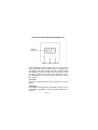
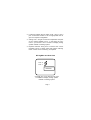
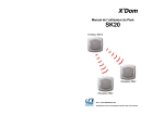
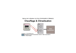
Digimax 210
Programmable Thermostat
Compatible with Maxi Controller
User Guide
Schema of the thermostat RF DigiMax 210
Ambient
temperature
Set Key Up Key Down Key
The RF DigiMax 210 thermostat does not need any extra
wiring and works within 30 meters range. It is equiped of a
secured RF code which the Maxi Controller will learn during
the installation process (see §8b). This code will assure that
the Maxi Controller will only answer to messages sent by
your DigiMax 210. This process is described at the end of
this manual.
1) To start :
Remove the battery insulation strip and check unit is functioning.
2) Operation :
The DigiMax 210 Digital Room thermostat is simple to use.
The Liquid Crystal Display continuously shows ambient temperature.
Page 2
To change the “Set Point” (i.e. temperature requested), press
and hold the “SET” key and at the same time press “+” or “-”
to select the temperature setting. The display will show the
“Set Point” until the “SET” button is released. The display will
then show the ambient temperature.
When the DigiMax 210 instructs your heating system to switch
on, a small flame symbol appears at the bottom right of the
display.
3) Installation :
DigiMax 210 Technical Data
Temperature Range :
Differential :
Ambient temperature :
Power Supply :
Battery Life :
Maintenance :
RF range :
5°C to 35°C in 1°C steps
16°C to 35°C selectable
<1°C at 4K per Hour
Operating 0°C to 45°C
2 type AA 1.5 v alkaline cells
2 years Typical
no user maintenance required
30 meters
Please read all installation instructions before proceeding.
The RF DigiMax 210 works with batteries. It does not need
any wire. If you wish it to replace an old cable thermostat,
isolate and secure the old wires, which are useless now. Do
not forget to cut the power when you take off the old thermostat.
Page 3
4) Position
The ideal position to locate the DigiMax 210 is about 1.5m
above floor level, accessible, free from extremes of temperature and draught. Do not mount it on an outside wall,
above a radiator or where it may be subjected to direct sunlight.
The radio link does not mean that the wiring has been simplified, but that the thermostat can be installed in any place of
your house to optimate your needs in heating.
We recommend you to make the installation with the Maxi
Controller before fixing your thermostat on the wall, in order
to be certain of its good operation at the selected place.
5) Fixing
1.The wall plate should be positionned with a minimum of
70 mm clearance all round to allow adequate air flow
2.Fix the wall-plate directly to a flat wall
3. Remove the battery insulation strip and check unit is functioning, place it on its wall-plate
6) Configuring
The unit is supplied with a 5°C minimum temperature set
point and configured as a heating thermostat as factory defaults. Two internal links can be used to reconfigure these
defaults.
1. Open the unit by slackening the retaining screw situated
in the bottom edge and hinging carefully upwards. Disengage the unit from the wall-plate and place it to one
side for safe keeping. Take off the batteries.
Page 4
2. Locate and identify the two option Links 1 and 2. Use a
pair of small wire cutters to cut the appropriate links to
give the required configuration.
3. Cutting Link 1 will give a minimum temperature set point
of 16°C (factory default is 5°C) : in that case, the minimum T° you can set is 16°C. Cut link 2 to display cooling
symbol instead of heating symbol.
4. Replace batteries being sure to observe the correct
polarities. Re-fit to plastic base and tighten retaining
screw. Check unit is functioning as required.
RF DigiMax 210 Rear View
Link 2
Link 1
Batteries
Cut Link 1 for 16°C minimum set point
Cut Link 2 to display cooling symbol
instead of heating symbol
Page 5
7) Battery replacement
A “flashing” battery low symbol will appear at the bottom left
of the display when the batteries start to approach the end of
their life. This indicates that they should be replaced within
the next month. Ultimately, the display will start flashing and
the thermostat will shut down until the batteries are replaced.
To replace the batteries, the following procedure should be
carried out.
1. Slacken the retaining screw on the unit and open by hinging upwards the top edge.
2. Remove batteries and fit two new “AA” alkaline cells taking care to observe the correct battery polarities. Check
unit is functioning
3. Re-fit it to the plastic base and check that the RF link still
operates. This can be easily done by adjusting the requested temperature under or over the level of the ambient temperature, in order to activate and disactivate several times the boiler.
Page 6
8) Connection to the the Maxi Controller
a) General operation
You can connect up to 4 DigiMax 210 to the Maxi Controller.
Depending on the information sent by the thermostats, the
Maxi Controller will send X10 messages on the power line
to turn On or Off X10 modules connected to your heaters or
boiler. These X10 modules can be Din appliance modules
(AD10) for boilers working on 230V or Universal modules
(UM7206) for boilers working on low voltage (up to 24V).
Each thermostat transmits the comfort setpoint and the ambient temperature. In the Maxi Controller you can enter a temperature setback , between 1 and 9 degrees.
When the Maxi Controller is in “Disarm” or “Arm home” mode,
it will turn On or Off the X10 module connected to the boiler
depending of the ambient temperature and the comfort
setpoint.
When the console is in “Arm Away” mode, the setback differential to the comfort setpoint is applied. Suppose the ambient temperature is 15 °C, the comfort setpoint is 20°C, with a
setback of 4°C : the comfort setpoint minus the setback is
20°C - 4°C= 16°C, so the console will send an On message.
Suppose that now the ambient temperature is 19°C, the comfort setpoint minus the setback is 20°C - 4°C= 16°C, so the
console will send an OFF message.
Page 7
b) Installation
Setthe security console mode switch to the THERM position.
2.To installa thermostatwith the console,press and hold
its + and - keys together for 3 seconds. The DigiMax 210
1.
3.
4.
5.
6.
will then transmit its unique digital code every 10 seconds
for the next 5 minutes. The display will show flash ‘]]]’
while this is happening.
After a few seconds you should hear a “bip” from the console and the first zone indicator should come on or, if you
have already intalled thermostats with the console, the
next available free zone will be indicated.
Go to the thermostat and press any key to stop the transmission. The display will stop flashing ‘]]]’ and return to
normal.
Repeat this procedure for thermostat 2, 3 and 4. The first
thermostat will be installed on zone 1, the second will be
installed on zone 2...., the fourth on zone 4.
On the security console, reset the mode switch to Run1 or
Run2
Each thermostat will transmit a message every 5 minutes. If
during 20 minutes, the console does not receive any signal
from a thermostat, its RECORD LED will flash.
You can then put the slide switch to the THERM position to
see which zone (thermostat) has a problem.
The Maxi Controller transmits an X10 message on the unit
code of the zone allocated by the security console (see above)
and on the house code of the console + 1.
i.e. : If the console is on Housecode A,
- thermostat on zone 1 will generate message on code B1,
Page 8
- thermostat on zone 2 will generate message on code B2,
- thermostat on zone 3 will generate message on code B3,
- thermostat on zone 4 will generate message on code B4.
If the console is on Housecode B,
- thermostat on zone 1 will generate message on code C1,
thermostat on zone 2 message on code C2 etc...
c) programming of the setback temperature
1. Set the security console mode switch to the INSTALL position.
2. Key in your PIN code (factory default 0000).
3. Press key number 9
4. Press ENTER
5. Key in the setback temperature between 1 to 9 in degree
Celcius.
6. Press ENTER.
7. Reset the mode switch to Run1 or Run2
d) Telephone
When theMaxi Controller is “Arm Away”, it is possible using
its dial-in function features, to apply or not the setback differential to the “comfort” setpoint:
To apply the temperature set back
1. Call the security console from a touch tone or mobile
phone.
2. The console will answer your call with 3 short beeps.
3. After these beeps, enter your PIN code via the phone (factory default 0000).
4. The console confirms a correct PIN code with 3 short
beeps (an erratic PIN code is indicated by one long beep).
Page 9
5. Dial via the phone “99#”, you will hear 3 short confirmation
beeps.
6. The setback differential is now applied to the comfort
setpoint.
Apply the comfort setting
1. Call the security console from a touch tone or mobile
phone.
2. The security console will answer your call with 3 short
beeps.
3. After these beeps, enter your PIN code via the phone (factory default 0000).
4. The console confirms a correct PIN code with 3 beeps (an
erratic PIN code is indicated by one long beep).
5. Dial via the phone 99*, you will hear 3 short confirmation
beeps.
6. The comfort setpoint is now applied.
e) To erase a registered thermostat
1. Set the security console mode switch to the THERM position. All indicators of occupied zones come on.
2. Key in your PIN code (factory default 0000).
3. Press key number 8
4. Press ENTER
5. Enter the required thermostat (1 to 4, e.g. press 3 for
thermostat 3)
6. Press ENTER
7. Reset the mode switch to the RUN 1 or RUN 2: zone
indicators go out.
Page 10
f) Trouble shooting :
1. Comfort temperature
If you do not manage to set a temperature level under
16 ° C, check that the thermostat has not been set in
order to avoid a lower temperature level.
Refer to the chapter 6 “configuring” of this user guide.
2. Operating troubles
If the boiler does not work on the request of the security
console, check the battery symbol on the DigiMax LCD.
Change the batteries if necessary. If the display does not
operates, it means that you probably missed the low battery symbol on the LCD : replace the batteries. If the batteries are taken off during more that 5 to 10 minutes, you
may need to re-install the thermostat on the security console.
EC DECLARATION OF CONFORMITY
Assesment of compliance of the product with requirements
relating to the essential requirements acc. to article 3 R&TTE
was based on annexe IV of the Directive 1999/5/EC and the
following standards : Radio: EN 300 220-1 : 1997; EMC :
ETS 300 683 : 1997; Electrical Safety : EN60950: 2000
0536!
Date: 05.06.2002
Page 11
F.Rossi
Approval Engineer