1
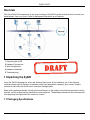
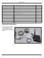
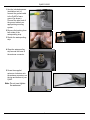
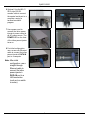
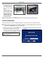
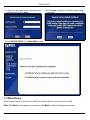
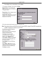
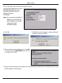
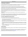
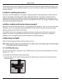
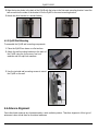
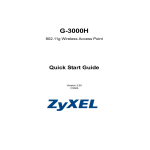
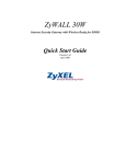
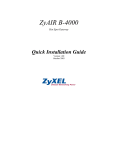
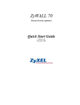
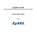
ZyAIR G-5100
Outdoor 802.11g Business Access Point/Bridge/Repeater
Quick Start Guide
Version 3.50
2/2005
ZyAIR G-5100
Overview
This Quick Start Guide shows how to set up and configure the ZyAIR to allow wireless clients to access your
wired network. See your User’s Guide for background information on all features.
1 Unpacking the ZyAIR
2 Hardware Connections
3 Initial Configuration
4 Hardware Installation
5 Troubleshooting
1 Unpacking the ZyAIR
Leave the ZyAIR’s shipping box intact and sheltered until arrival at the installation site. If the shipping
container shows signs of damage, immediately notify the transportation company. Upon receipt, inspect
contents to make sure that there are no missing or damaged parts.
Retain all the packing materials (including all internal boxes). In the unlikely event that the equipment must be
returned, use the original packing materials for return shipment. The packing materials are also recommended
for transporting the equipment from location to location.
1.1 Packaging Specifications
2
ZyAIR G-5100
Accessories
Specification/Description
Quantity
Inline Power Injector (PoE)
Input 100 ~ 240VAC 50/60Hz, Output 800mA at -48VDC
1
Wall-plug AC Power Cord
(1.8m)
1
RS232 Console Cable
MIL-C-5015 STP (Shielded Twisted Pair) (2.0m)
1
Uplink Ethernet Cable
MIL-C-5015 UTP (Unshielded Twisted Pair) (1.8m)
1
Grounding Cable
UL1015 (3.0m)
1
RJ45 Ethernet Cable
MIL-C-5015 STP (30.0m)
1
Antennas
5dBi omni-direction rubber antenna
2
Waterproofing Strip
2
Mounting Brackets
Wall mount brackets, Mast mount brackets
1 pair, 1 pair
Spanner
Installation tool
1
CD-ROM
Quick Start Guide and User’s Guide
1
2 Hardware Connections
Configure and test the ZyAIR
before installing it in a hardto-reach location. Use the
following steps to connect the
ZyAIR.
3
ZyAIR G-5100
1 Use the included spanner
(installation tool) to
connect the ground cable
to the ZyAIR’s frame
ground (as shown).
Connect the other end of
the ground cable to an
appropriate grounding
system.
2 Remove the backing from
both sides of the
waterproofing strip.
3 Stretch the waterproofing
strip.
4 Wrap the waterproofing
strip around the base of
the antenna connector.
5 Screw the supplied
antennas clockwise onto
the antenna connectors on
the top and bottom of your
ZyAIR.
Note: Do not over-tighten
the antennas.
4
ZyAIR G-5100
6 Optional: Use the MIL-C5015 style RS-232
console cable to connect
the special serial port to a
computer running a
terminal emulation
program.
7 Use a power cord to
connect the inline power
injector’s power socket to
an AC power source. The
POWER LED on the front
of the inline power injector
turns on.
8 For initial configuration,
use a cross-over Ethernet
cable to connect the inline
power injector’s DATA IN
port to a computer.
Note: After initial
configuration, use a
straight-through
Ethernet cable to
connect the inline
power injector’s
DATA IN port to a
LAN connection
(such as to a switch
or router).
5
ZyAIR G-5100
9 Connect the MIL-C-5015
style Ethernet connector
to the special Ethernet
port on the bottom of the
ZyAIR.
Connect the RJ-45
Ethernet connector (the
other end of the special
Ethernet cable) to the
POWER & DATA OUT
port on the front of the
inline power injector.
Note: The ZyAIR starts. The ACTIVE LED on the front of the inline power injector turns on.
3 Initial Configuration
Use Internet Explorer 6.0 and later or Netscape Navigator 7.0 and later versions with JavaScript enabled.
Note: Even though you can connect to the ZyAIR wirelessly, it is recommended that you connect your
computer to the DATA IN port for initial configuration.
1 Launch your web browser. Enter 192.168.1.2 (the
ZyAIR’s default IP address) as the address.
If the login screen does not display, see Section
5.1 on page 14 to set your computer’s IP address.
2 Click Login (the default password 1234 is already
entered).
6
ZyAIR G-5100
3 Change the login password by entering a new
password and clicking Apply.
4 Click Apply to replace the ZyAIR’s default digital
certificate.
5 Click WIZARD SETUP in the MAIN MENU screen.
3.1 Wizard Setup
Use the setup wizard to configure your ZyAIR for wireless stations to access your wired LAN.
Note: Click Next in each screen to continue or click Back to return to the previous screen.
7
ZyAIR G-5100
Your settings are not saved when you click Back.
1 This screen is optional. You can just click Next.
System Name is for identifying the
ZyAIR. You can enter your computer's
"Computer Name".
Domain Name: Enter a domain name if
your ISP requires one for
authentication; otherwise you can leave
it blank or set to whatever may have
displayed automatically.
2 Use the second wizard screen to set up the wireless LAN.
Note: The wireless stations and ZyAIR must use the same ESSID, channel ID and WEP encryption key
(if WEP is enabled) for wireless communication.
The ZyAIR has two WLAN adapters.
Select one to configure.
Enter a descriptive name to identify the
ZyAIR in the wireless LAN.
Click Scan to have the ZyAIR
automatically select a channel and
display it in the Channel ID field.
Select 64-bit or 128-bit to encrypt data
frames before transmitting them over
the wireless network.
Select Disable to turn off WEP data
encryption.
Select ASCII or HEX WEP key input
method and then follow the on-screen
instructions to set up the WEP keys.
Click Next to continue.
8
ZyAIR G-5100
3 Fill in the fields in the last wizard configuration screen.
If you have an IP address to use, select
Use fixed IP address and enter it
along with the subnet mask and
gateway IP address.
Click Finish.
Note: If you change the ZyAIR’s IP
address, you must use the
new IP address if you want
to access the web
configurator again.
4 Click Ok.
5 Click Yes if you do not want to configure advanced
features, otherwise click No.
6 This final wizard screen displays if you clicked No.
You may return to the MAIN MENU and continue
to configure your ZyAIR.
7 Change the wireless parameter settings in the wireless stations to match those of the ZyAIR. Refer to your
wireless adapter’s documentation
9
ZyAIR G-5100
4 Hardware Installation
In general, the best location for the access point is at the center of your intended wireless coverage area. It is
recommended that you do the initial configuration of the ZyAIR prior to mounting.
The ZyAIR can be mounted on the side of a building or mounted to an antenna mast as described:
A wall (side) mount allows for mounting an antenna (mast) on the side of a building or on the side of an
elevated penthouse. This will provide a convenient mounting location when the roof overhang is not excessive
and/or the location is high enough to provide a clear line of sight.
An antenna couples RF signals onto air. A transmitter within a wireless device sends an RF signal to the
antenna, which propagates the signal through the air. The antenna also operates in reverse by capturing RF
signals from the air.
Choosing the right antennas and positioning them properly increases the range and coverage area of a
wireless LAN.
In most situations mounting an antenna directly to the wall will not allow you to properly align the antenna with
the corresponding antenna at the opposite end of your wireless link. As poor alignment will typically result in
poor performance, it is advised that you mount the ZyAIR to a mast.
4.1 Antenna Mast/Antenna Requirements
To accommodate the ZyAIR, the mast must satisfy the following requirements:
• The construction of the mast must be of a sturdy, weatherproof and non-corrosive material, for example, galvanized or stainless steel construction pipe.
• Typical diameter of the mast should be between 35 mm (1.4”) and 41 mm (1.625”). Subject to the type of mast
that you intend to install, other diameters are possible.
• The height of the antenna mast must be sufficient to allow the antenna to be installed at least 1.5 m (5’) above
the peak of the roof. If the roof is metal, then the height of the antenna should be a minimum of 3m (10’) above
the roof.
• The mast or wall-bracket must be free from any substance that may prevent a good electrical connection with
the antenna, for example, paint.
4.2 Grounding
A safe grounding system is necessary to protect your outdoor installation from lightning strikes and the buildup of static electricity.
Direct grounding of the antenna mast, ZyAIR and surge arrester are very important. The ZyAIR has a built in
surge arrester. The ZyAIR’s frame ground (see Section 3 on page 2) should be connected to the same
grounding system as the antenna mast and the AC wall outlet.
10
ZyAIR G-5100
The grounding system must comply with the National Electrical Code and safety standards that apply in your
country. Always check with a qualified electrician if you are in doubt as to whether your outdoor installation is
properly grounded.
4.3 What is Lightning Protection?
All outdoor electronic equipment is susceptible to lightning damage. Proper grounding to national and local
codes is instrumental in providing human safety. Lightning Protection is used when a customer wants to
maximize the reliability of the electronic system by diverting the excess energy that can be induced on any
transmission lines (data, power) though a series of surge protection devices. The energy is dissipated through
heat and is also diverted to the ground.
4.4 Why is Additional Protection Recommended?
Lightning, even with the built-in protection, can still damage ZyAIR equipment. This can occur for any number
of reasons, such as an improperly grounded installation or if the amount of transient energy from nearby
lightning exceeds what the devices can handle.
If the ZyAIR unit fails due to damage from lightning, the link is out-of-service until the unit is replaced or
repaired. An external, reverting protection device can provide a higher level of protection, and greater
probability of surviving lightning strikes without damage to the ZyAIR equipment.
4.5 Mounting the ZyAIR
Use the included spanner with the mounting screws and nuts.
Note: Make sure the screws are securely fixed to the wall or mast and strong enough to hold the weight
of the ZyAIR with the connection cables.
4.5.1 ZyAIR Mast Mounting
You can mount the outdoor component of your ZyAIR directly to a pole with an outside diameter of 37.5mm ~
62.5mm (1.5” ~ 2.5”).
To assemble the ZyAIR mast mounting components:
1 Insert the U-bolt into the mast-mounting bracket and attach the two nuts with one lock washer and one
split-lock washer.
11
ZyAIR G-5100
2 Align the top two holes in the back of the ZyAIR with the holes in the first mast-mounting bracket. Insert the
two screws into the sides of the bracket to fix the ZyAIR to the mast-mounting bracket.
3 Attach the other bracket in a similar fashion.
4.5.2 ZyAIR Wall Mounting
To assemble the ZyAIR wall mounting components:
1 Place the ZyAIR face down on a flat surface.
2 Attach the wall mounting brackets to the back of
the ZyAIR using the four screws, four lock
washers and four split-lock washers.
3 Use the included wall mounting screws to mount
the ZyAIR on the wall.
4.6 Antenna Alignment
Omni-directional antennas are characterized by a wide radiation pattern. Therefore alignment of this type of
antennas is less critical than for directional antennas.
12
ZyAIR G-5100
For omni-directional antennas mounted on a table, desk, and so on, point the antenna up. For omni-directional
antennas mounted on a wall or ceiling, point the antenna down. For a single AP application, place omnidirectional antennas as close to the center of the coverage area as possible.
For directional antennas, point the antenna in the direction of the desired coverage area.
For optimal performance of your wireless link, make sure that the antennas are properly aligned (facing one
another “eye-to-eye”). To align the antennas:
Use binoculars and/or a map of the area and compass to point the antennas to one another.
Optimize antenna alignment if required, by making small modifications in the antenna orientation.
Use the web configurator’s wireless link test.
Alternatively, consult a professional antenna installation service to optimize the antenna alignment.
4.7 Antenna Connector Type
The ZyAIR is equipped with a standard-N type jack, so it will work with any 2.4GHz wireless antenna with a
standard-N type connection.
Note: Make sure the antennas are securely screwed onto the antenna connector. The ZyAIR has
standard-N type connectors (as shown next).
5 Troubleshooting
Problem
Corrective Action
The POWER and/or
ACTIVE LED are off on
the inline power
injector.
Make sure the power cord is connected into an adequate power supply and that the
power supply is turned on.
The ACTIVE LED on
the inline power
injector is off.
Disconnect and reconnect the power supply. If the error persists, you may have a
hardware problem. In this case, you should contact your vendor.
Check the cable connection to the ZyAIR special Ethernet port.
Make sure your computer’s network card is working properly.
13
ZyAIR G-5100
Problem
Corrective Action
I cannot ping any
computer on the LAN.
If all of the inline power injector LEDs are off, check the cables between the ZyAIR and
your computer or hub.
I cannot access the
Internet.
Make sure the ZyAIR is connected to the network.
Make sure you entered your username correctly. A username may be case-sensitive.
5.1 Set Up Your Computer’s IP Address
This section shows you how to assign your computer a static IP address in the 192.168.5.2 to 192.168.5.254
range with a subnet mask of 255.255.255.0. This is ensures that your computer can communicate with your
Prestige. The following instructions are for the Windows 2000, Windows NT and Windows XP operating
systems.
1 In Windows XP, click Start, Control Panel.
In Windows 2000/NT, click Start, Settings, Control
Panel.
2 In Windows XP, click Network Connections.
In Windows 2000/NT, click Network and Dial-up
Connections.
3 Right-click Local Area Connection and then click
Properties.
4 Select Internet Protocol (TCP/IP) (under the
General tab in Windows XP) and click Properties.
5 The Internet Protocol TCP/IP Properties screen
opens (the General tab in Windows XP).
6 Select Use the following IP address and fill in the IP
address (choose one from192.168.1.3 to
192.168.1.254), Subnet mask (255.255.255.0), and
Default gateway (192.168.5.1) fields.
7 Click OK to close the Internet Protocol (TCP/IP)
Properties window.
8 Click Close (OK in Windows 2000/NT) to close the
Local Area Connection Properties window.
9 Close the Network Connections screen.
5.2 Procedure to View a Product’s Certification(s)
1 Go to www.zyxel.com.
2 Select your product from the drop-down list box on the ZyXEL home page to go to that product's page.
3 Select the certification you wish to view from this page.
14