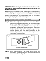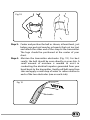
1
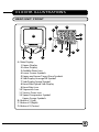
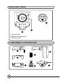
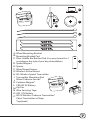
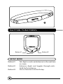
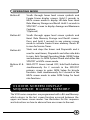
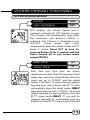
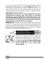
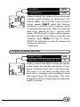
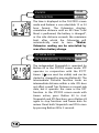
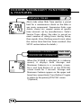
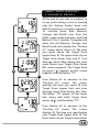
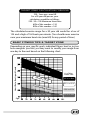
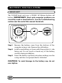
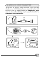
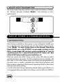
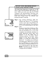
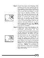
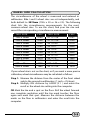
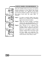
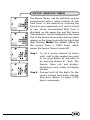
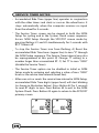
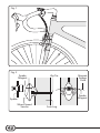
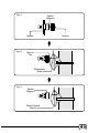
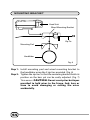
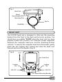
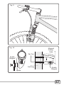
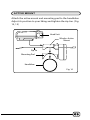
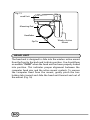
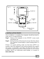
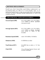
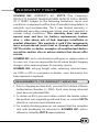
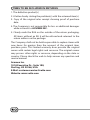
ENGLISH
CONTENTS
1. INTRODUCTION
2. WARNINGS & CAUTIONS
3. V100HR ILLUSTRATIONS
HEAD UNIT
COMPONENT ILLUSTRATIONS
3
4
5
6
4. BUTTON FUNCTIONS
SETUP MODE
OPERATING MODE
8
9
5. V100HR SCREEN DISPLAY SEQUENCE:
BI-LEVEL MEMORY
9
6. V100HR PRIMARY FUNCTIONS
UPPER SCREEN MODES
Speed, Trip Distance, Ride Time, Total Time
Average Speed, Maximum Speed
Speed*, Cadence*
11
12
13
LOWER SCREEN MODES
Heart Rate, Percent Of Maximum HR
Clock, Odometer, Stopwatch,
Intermediate Distance
Dual Bike Memory, Heart Rate Reading
13
14
15
7. V100HR SECONDARY FUNCTIONS
& FEATURES
Service Timer, Average Cadence*,
Maximum Cadence*
Low Battery Alert, Speed Comparator
Freeze Frame Memory
Heart Rate Memory Storage & Recall
AUTO START
SLEEP MODE
16
17
18
19
20
20
AUDIBLE & VISUAL ALARMS
RIDE DATA RESET
ALL CLEAR TOTAL RESET
8. TARGET ZONE & FITNESS TRAINING
9. BATTERY INSTALLATION
HEAD UNIT
WL WIRELESS SPEED TRANSMITTER
HEART RATE TRANSMITTER
10. SETUP MODE & PROGRAMMING
11. INSTALLATION
21
21
21
22
26
27
28
28
WIRED MODEL INSTALLATION
Speed Sensor & Magnet
Mounting Bracket
Head Unit
40
44
45
WIRELESS MODEL INSTALLATION
Speed Transmitter & Magnet
Active Mount
Head Unit
INSTALLATION TESTS
ATTACHING YOUR HEART MONITOR
46
49
50
51
52
12. TROUBLESHOOTING
PROBLEM/ITEMS TO CHECK/SOLUTION: CYCLING
PROBLEM/ITEMS TO CHECK/SOLUTION: HEART
13. CARE & MAINTENANCE
BATTERY REPLACEMENT
14. TECHNICAL SPECIFICATIONS
15. WARRANTY POLICY
REQIREMENTS FOR WARRANTY SERVICING
ITEMS TO BE INCLUDED IN RETURNS
54
55
56
57
57
59
60
INTRODUCTION
Thank you for purchasing a Vetta V100HR cycle computer and
heart rate monitor. The V100 series computers represent the latest
evolution in Vetta's computer line and are designed for cycling
enthusiasts and multi-sport athletes alike. In particular, the V100HR
model offers a wide range of unique features and functions such as
Dual Bike Memory, Intermediate Distance and Stopwatch readings,
multiple Heart Rate functions and a Service Timer. For people
interested in fitness, the V100HR offers Target Zone Heart Rate
functions that will increase the effectiveness of your workout by
monitoring and quantifying your results every step of the way. For
most individuals, as little as 20 minutes in your target heart rate
zone each session is enough to achieve substantial health
improvements. Please take time to familiarize yourself with all the
functions of the V100HR model so you can take full advantage of
its programs. And don't forget to store this manual in a safe place
for future reference!
WARNINGS & CAUTIONS
• Vetta cycle computers are sophisticated electronic instruments.
Vetta recommends that this product be installed by a qualified
bicycle retailer. Failure to read these instructions and/or
improper installation of this device may void the warranty. If in
doubt about any part of the installation or operation of this
product, please consult your local bicycle retailer for
clarification.
• The head unit and chest transmitter are water resistant and
sealed to withstand wet weather conditions. However, do not
deliberately place them in water.
• Avoid leaving the head unit exposed to extremely hot weather
conditions.
• Overexertion can cause serious injury, including heart attacks.
Some individuals cannot safely elevate their heart rate to the
levels of typically used heart rate training zones. No one should
begin an exercise program without first obtaining medical
clearance, especially if there is a personal or family history of
heart disease, high blood pressure, or if you are over age 40,
have diabetes, high cholesterol, smoke cigarettes, are
overweight or are taking certain medications. Stop exercising
and seek medical attention if you notice signs of overexertion
or heart problems, such as pain or pressure in the left or midchest area or left neck, shoulder or arm, light-headedness, cold
sweat, unusual paleness or fainting. Also note that the signals
used by this monitor may interfere with a pacemaker or other
implanted devices. Consult the manufacturer of the implant
device and/or your physician prior to using this monitor.
• Vetta encourages you to ride safely. Wear a helmet every time
you ride, use front and rear lights at night, and always keep
your eyes on the road ahead of you.
V100HR ILLUSTRATIONS
HEAD UNIT: FRONT
12
11
13
1
A
2
10
7
9
B
D
6
8
C
A Main Display
1 Upper Display
2 Lower Display
3 Audible Alarm Icon
4 Lower Screen Symbols
5 Upper and Lower Target Zone Symbols
6 Sub-Display Average HR Symbol
7 Sub-Display Speed Symbol
8 Heart Rate/Speed Sub-Display
9 Heart Rate Icon
10 Stopwatch Icon
11 Service Timer Icon
12 Speed Comparator Symbol
Upper Screen Symbols
B Button #1 (Left)
C Button #2 (Right)
D Button #3 (Center)
5
4
3
N
E
P
CL
O
S
E
O
HEAD UNIT: REAR
CR
20 3 2
C
B
A
A Contact Pins
B Battery Compartment
C Battery Cover
COMPONENT ILLUSTRATIONS
A
G
E
B
C
D
F
H
K
0
CR2 32
L
CE
LT
L
LL
3VO
J
IT HIU M
M
N
A Wired Mounting Bracket
B Mounting Bracket Pad
C Riser Handle Bar Bracket Pad (You may choose B or C
according to the style of your bicycle handlebar.)
D Spoke Magnet
E Spacer
F Wired Speed Sensor
G Wireless Active Mount
H WL Wireless Speed Transmitter
I Transmitter Mounting Pad
J Wired Cadence Sensor*
P
K Cadence Magnet*
L CR2032 3V Battery
M Zip Ties
N Wire Securing Tape
O A23 12V Battery
P WL2X Wireless Cadence Transmitter*
Chest Transmitter w/Strap
*(optional)
O
I
Q
BUTTON FUNCTIONS
Button #1
Button #3
Button #2
SETUP MODE
Button #1
Button #2
Button #3
Sets digits or units and advances to the next item
or screen.
Advances digits and toggles through units.
Hold for fast advance.
Has no function in Initial Setup.
OPERATING MODE
Button #1
Button #2
Button #3
Buttons #1 &
#2
Scrolls through lower level screen symbols and
Freeze Frame display screens. Hold 2 seconds in
HR/% screen mode to display HR data from Heart
Rate Memory Storage and Recall. Hold 2 seconds in
SPD/CAD* screen to display Average and Maximum
Cadence.
*(Optional)
Scrolls through upper level screen symbols and
Heart Rate Memory Storage and Recall screens.
Press and hold 2 seconds in any primary screen
mode to activate Freeze Frame memory. Resets RT
to zero for Service Timer.
Starts and stops the timers and Stopwatch and is
used to reset timers, Stopwatch and other ride data
to zero. Exits Normal Operating Mode (NOM) Setup
and advances to NOM System Check and either the
SPD/DST or HR/% screen mode.
With RT/TT timers turned OFF, hold both buttons
simultaneously for 2 seconds in the SPD/DST
primary screen to enter NOM Setup for bicycle
functions. Hold simultaneously for 2 seconds in the
HR/% screen mode to enter NOM Setup for heart
rate functions.
V100HR SCREEN DISPLAY
SEQUENCE: BI-LEVEL MEMORY
The V100 series computers are programmed with a Bi-Level Memory
which returns to the last screen function accessed between the
upper and lower screen modes. See illustration for this sequence
and instructions on how to advance from one screen to the next.
1
LOWER SCREEN
MODES
2
UPPER SCREEN
MODES
SPD
DST
2
HR
%
RT
TT
1
1
CLK
ODO
1
BI-LEVEL
2
MEMORY
2
1
STP
IDS
AVG
MAX
2
SPD*
CAD
*(Optional)
2
V100HR PRIMARY FUNCTIONS
UPPER SCREEN MODES
SPEED
SPD
TRIP DISTANCE
DST
SPD displays the current Speed and is
updated continuously. DST displays current
Trip Distance and automatically resets after
the maximum trip distance (999.9) is
achieved. Trip Distance is displayed in the
SPD/DST screen mode and starts
automatically when the wheel rotates and TT
timer is active. Reset DST to zero by
pressing Button #3 for 2 seconds with the
timers turned off in any screen mode
except SPD/IDS.
RIDE TIME
RT
TOTAL TIME
TT
Ride Time and Total Time are shown
simultaneously. Ride Time (RT) measures actual
riding time and starts automatically when the
timers are set to "0:00:00" and the wheel
rotates. Total Time (TT) shows the total elapsed
trip time from start to finish. Like RT, TT starts
automatically when the wheel rotates ONLY
when the timers are set to "0:00:00", or it can be
started manually by pressing Button #3 in the
RT/TT screen mode ONLY. TT can only be
stopped manually by momentarily pressing
Button #3 in the RT/TT screen mode at the end
of a ride. To reset both RT and TT to zero, turn the timers off and
press Button #3 for at least 2 seconds. Note: Whenever TT is
activated, the stopwatch icon appears; otherwise it does not
appear. The TT Timer must be active in order for the RT Timer to
accumulate Ride Time and for the computer to calculate current
ride and heart rate memory data.
CAUTION: If RT and TT timers are not 0:00:00 and you have
stopped them manually, then they MUST be restarted
manually by pressing Button #3 in the RT/TT mode. If not,
the computer will not record speed or other ride or heart rate
memory data. RT and TT Timers can be manually activated or
deactivated only from the RT/TT screen mode.
RIDING TIP: If the bike is in motion and Button #3 is held down
in the RT/TT screen mode with the timers deactivated, the ride
timers reset to 0:00:00. When Button #3 is released, both RT and TT
will start with the next wheel input. This is a good way to begin
timing a race or training ride with a rolling start.
AVERAGE SPEED
AVG
MAXIMUM SPEED
MAX
Average and Maximum Speed readings are
displayed simultaneously in the AVG/MAX
screen mode. Average Speed is updated every
0.1 miles or Km traveled. Reset both to zero
by pressing Button #3 for 2 seconds with
timers turned off in any screen mode
except STP/IDS.
SPEED*
SPD
CADENCE*
CAD
When installed, the Cadence kit measures and
displays pedal Cadence in Revolutions Per
Minute (RPM). The SPD/CAD screen function
letters appear ONLY when the Cadence
hardware is installed and a Cadence signal
received by the head unit. After a current ride
data reset, (Button #3 for 2 seconds with
timers off) the function letters will disappear,
but they will will come back on with the next
Cadence input. Note: RT and TT timers
MUST be activated in order for Speed and
Cadence to function.
* (Optional)
LOWER SCREEN MODES
HEART RATE
PERCENT OF MAXIMUM HR
HR
%
Displays current Heart Rate in beats per minute
on the upper line and the percentage of your
preset maximum heart rate on the lower line.
The heart icon will blink steadily when the
head unit is receiving and recording a heart
rate signal from the transmitter. This icon
disappears from the display when no heart rate
signal is received.
CLOCK
CLK
ODOMETER
ODO
The time is displayed in the CLK/ODO screen
mode and features a user selectable 12 or 24
hour format. The Odometer displays
cumulative distance until an All Clear Total
Reset is performed, the battery is changed*,
or the ride distance exceeds the maximum
limit, after which the Odometer will
automatically reset to zero. *Note:
Odometer reading can be reinstalled by
user after a battery change.
STOPWATCH
STP
INTERMEDIATE DISTANCE IDS
The independent Stopwatch is operated by
Button #3 in the STP/IDS screen mode. STP
operates in conjunction with the RT/TT
timers (
icon must be visible) and can be
started or stopped by pressing Button #3. The
Intermediate Distance function tracks an
intermediate distance within a ride. IDS does
not affect overall Trip Distance or current ride
data, but it operates the same as the DST
function. In the STP/IDS screen mode with
timers active, press Button #3 to start
Stopwatch and IDS functions; press Button #3
again to stop functions and freeze data for
review. Reset both Stopwatch and IDS to zero
by pressing Button #3 for 2 seconds.
DUAL BIKE MEMORY
I
II
The V100HR can be calibrated for two bicycles.
It will store separate Wheel Size, Service Timer,
Odometer, Age and Heart Rate Target Zone
settings, as well as different formats for Time,
Speed and Distance. The current bike number
(I or II) is always displayed in the lower right
corner of the screen. To switch the computer
quickly from Bike I to Bike II, go to the first
screen in the Normal Operating Mode Setup
program for cycling. (See SETUP section
below for details.)
HEART RATE READING
The V100HR monitor displays Heart Rate in
the lower left screen segment. The range is
40 to 240 beats per minute, and the blinking
heart icon ( ) displays as long as a signal is
being received. When the monitor is toggled
to the HR/% screen mode (Button #1),
current Heart Rate is displayed on the upper
line and the Percent of Maximum HR on the
lower line. Current Speed is then displayed
in this small screen segment and the letters
"SPD" appear immediately above it. (see
screen illustrations).
V100HR SECONDARY FUNCTIONS
& FEATURES
SERVICE TIMER
Alerts rider when Ride Time reaches a preset
limit for a maintenance check on the bike or
any main component. Suspension forks, rear
shocks, chains, etc. require service at specific
time intervals set by manufacturers. Vetta's
Service Timer allows the rider to preset an
exact number of riding hours during Setup,
then signals (slow, flashing wrench icon) when
the service time limit has been reached. (See
SETUP section below for details.)
AVERAGE CADENCE*
AVG CAD
MAXIMUM CADENCE* MAX CAD
When the V100HR is attached to a cadence
mount, it displays both Average and
Maximum Cadence in a secondary screen.
Press and hold Button #1 in the SPD/CAD
screen mode for 2 seconds. Average and
Maximum Cadence appear on the upper and
lower lines respectively. Press Button #1 again
to return to the primary SPD/CAD screen.
*(Optional)
LOW BATTERY ALERT
The V100HR Service Timer icon has been
programmed to signal low battery power in
the head unit. When the battery runs low
and needs to be replaced, the Service Timer
icon (
) will illuminate and stay "on" (no
blinking). Replace the head unit battery as
soon as possible. Rapid blinking of the
Service icon indicates both low battery
power and expiration of the preset service
time interval.
SPEED COMPARATOR
The Speed Comparator symbols on the left
side of the display screen indicate whether
current Speed is above or below current
Average Speed. A positive ( ) or negative
( ) symbol appears in the upper left part of
the screen in all primary screen modes. The
Speed Comparator symbols do not appear if
Speed (SPD) and Average Speed (AVG) are the
same.
FREEZE FRAME MEMORY
SPD/DST
2
SPD/DST
1
RT/TT
1
1
AVG/MAX
1
HR/%
2
SPD/DST
Freezes ride data from 4 primary
screens for review at any point during a
race or training ride. To activate Freeze
Frame, press and hold Button #2 for 2
seconds in any primary screen mode.
The screen will flash to indicate it has
been frozen. The computer will
continue to record ride data. Advance
through the frozen screens by pressing
Button #1 repeatedly. Press Button #2 to
cancel Freeze Frame and return to the
previous screen mode.
Note: If Ride Time/Total Time (RT/TT) is
not running at the time Freeze Frame is
activated (Button #2 for 2 seconds),
previously frozen ride data will be
displayed. At the end of the ride, user
can view both "end-of-ride" data (by
stopping the timers and toggling
through the primary screens) and the
last Freeze Frame data screens recorded
(by activating Freeze Frame with the
RT/TT timers turned off).
HEART RATE MEMORY
STORAGE & RECALL
At the end of your ride or workout, or
at any point during a race or training
ride, this feature freezes heart rate
data for review in a 4 screen sequence.
To activate Heart Rate Memory
Storage and Recall, start from the
HR/% screen mode and press and hold
Button #1 for 2 seconds. Computer will
enter the HR Memory Storage and
Recall mode and display the "Position
#1" screen which shows: A) The time
you spent above the Target Zone
(upper line), B) The upper limit of your
Target Zone (lower line), and C) Your
Average Heart Rate during the time
spent above your Target Zone (lower
left screen segment). The Target Zone
up arrow ( ) appears on this screen
together with the letters "TZ".
1
2
2
2
2
Press Button #2 to advance to the
"Position #2" screen. This screen
displays the time you spent IN your
Target Zone (upper line) and your
Average Heart Rate during this time.
The letters "IN" appear on the lower
line, along with both Target Zone
arrows ( ) and the letters "TZ".
Press Button #2 to advance to the
"Position #3" screen. This screen
displays A) The time you spent below
your Target Zone (upper line), B) The
lower limit of your Target Zone (lower
line), and C) Your Average Heart Rate during the time spent
below your Target Zone (lower left screen segment). The Target
Zone down arrow ( ) appears on this screen together with the
letters "TZ".
Press Button #2 to advance to the Position #4 screen. This screen
displays your Average (upper line) and Maximum (lower line) Heart
Rates for the entire ride. The letters "AVG/MAX" appear at the top
of this Position #4 screen. Note: To exit from HR Memory Storage
and Recall at any time, press Button #1 and return to the primary
HR/% screen mode.
AUTO START
If the RT/TT timers read zero (0:00:00), the Vetta V100HR
computer automatically starts as soon as it receives input from
the wheel. The RT and TT timers are activated and other ride
data begins to accumulate (SPD, DST, AVG & MAX SPD, CAD*,
AVG & MAX CAD*, ODO, HR, %).
Note: Any time the timers are stopped manually and they are
not cleared, RT and TT must be restarted manually by pushing
Button #3 in the RT/TT screen mode.
*(Optional)
SLEEP MODE
To conserve battery life, the V100HR
computer is programmed to enter a Sleep
Mode after receiving no input from buttons,
wheel motion, cadence or heart rate for 5
minutes. In this mode the V100HR screen
displays only the time of day. The computer
exits Sleep mode automatically* when it
receives input from buttons or wheel/crank
motion and then returns to the screen last
displayed. Clock, Stopwatch, and Total Time
(for the ride) continue to run during the Sleep Mode.
*Note: Wired version only. In the wireless version the computer
will "wake up" only when one of the buttons is pushed.
AUDIBLE & VISUAL ALARMS
The V100HR features both Audible (
) and Visual HR Target
Zone Alarms. These alarms signal when the user's heart rate rises
above or falls below the pre-established HR Target Zone during
an exercise session. The Visual Alarm always displays; the Audible
Alarm can be turned on or off as the user chooses. See the Setup
section of this manual for details.
RIDE DATA RESET
To reset current ride data and Freeze Frame data to zero (DST, RT,
TT, AVG & MAX SPD, AVG & MAX CAD*, STP, IDS), make sure the
timers (RT/TT) are turned OFF and press Button #3 for 2 seconds in
any primary screen mode except STP/IDS. Note: All stored heart
rate data, including Average and Maximum HR and the time spent
in, above and below your Target Zone, is also cleared during this
reset.
* (Optional)
ALL CLEAR TOTAL RESET
All settings entered in Initial Setup, as well as all accumulated ride
data, can be cleared by performing an All Clear Total Reset. To clear
the computer, press all three buttons simultaneously and hold for
5 seconds in any screen mode. When the computer is reset, the
master screen will appear and show all LCD segments for 3
seconds. The computer will then automatically enter Initial Setup
mode to be reprogrammed.
TARGET ZONE & FITNESS TRAINING
DETERMINING YOUR TARGET ZONE
What is Target Zone Heart Rate Training? In order to benefit the
most from your workout, you need to become familiar with your
heart rate training zone. By working within the correct range, you
will achieve your fitness goals and strengthen your cardiovascular
system in less time. Here is basically how it works.
Effective conditioning requires that you maintain your heart rate at
the proper level for at least 20 minutes per workout (or per day). At
too high of a heart rate your activity can become counter effective.
For most people, as your heart rate exceeds 85% (the upper limit),
your body begins to become anaerobic and produce acids. This
also burns less fat which can begin to burn and strain muscles, and
even start storing fat. As for the lower limit, this number tells you
when you have reached a level of intensity that is productive. A
heart monitor will tune you into your body's internal activity level
and helps prevent injury or worse.
To make this part easy for you, the V100HR automatically sets the
correct target zone for you after you enter in your age in the heart
rate setup mode. The internal auto-setting is based on a generally
accepted standard range of 65 to 85% of your maximum HR (where
max HR = 220 - Age).
There are many variations of formulas for calculating target zones.
In most cases they will come up with a range very close to or the
same as the auto-setting of the V100HR. If you prefer to fine-tune or
program your own limits, this can also be done in the HR Setting
Mode (see page 30). The internal automatic TZ calculation is based
on the following example:
TARGET ZONE CALCULATION FORMULA
220 - Your age = max HR
For a 30 year old person, your
calculations would be as follows:
220 - 30 = 190 Maximum Heart Rate
65% of this number = 124
85% of this number = 162
The calculated exercise range for a 30 year old would be a low of
124 and a high of 162 beats per minute. (You should never exercise
near your maximum heart rate (max HR) for any period of time.)
BASIC FITNESS TIPS & TARGET ZONE
Heart Rate - Beats per Minute
Depending on your specific goals, individual fitness level or just on
how energetic you feel, you may want to modify your range from
one day to the next based on the following chart:
Age:
Ana
ero
Aero
bic
Zon
e
bic Z
one
Fat B
urnin
g
% of Max.
Heart rate
85% to Max
65% to 85%
Zone
55% to 65%
Warm-up Cool Down
55% or less
STRETCHING
Begin and end every workout with stretching. Stretching done
before your workout increases flexibility to help prevent muscle
strain or injury and stretching after, loosens tight muscles and helps
prevent soreness.
• Stretch before warm up and after cool down.
• Stretch slowly and gently, never bounce or stretch to a point
of pain.
• Hold each stretch 30-60 sec. and exhale as you extend
stretches.
WARM UP & COOL DOWN: 55% OR LESS
Start every exercise with a slow and gradual warm up and end with
a slow and gradual cool down. Smoothly easing into and out of
strenuous activity helps your body prepare your metabolism and
blood flow to efficiently break down fat and change over from one
intensity level to another. Going into your target zone too quickly
can cause your heart rate to increase too rapidly causing you to
loose your energy too soon, strain yourself or possibly worse.
• Slowly bring your heart rate to a level just below the lower
limit of your target zone.
• Maintain heart rate at this level for 5-10 min.
THE FAT BURNING ZONE: 55-65%
This range is recommended for those who haven't worked out in
a long time, are trying to loose weight, those at a high risk for
heart problems or if you're just not feeling 100% one day. It is
intended for low intensity and/or long duration exercise. The
lower intensity helps you maintain your exercise for longer
periods of time. When exercising for weight loss or starting a new
exercise routine, longer duration is more important and much
healthier than higher intensity.
• Build up gradually to 30-60 min. per workout.
• Workout 3 or 4 times per week.
THE AEROBIC ZONE: 65-85%
This range is recommended for those in good physical condition
who have been exercising on a consistent basis for an extended
period of time. Exercising at this range helps improve your fitness
level and prevent injury caused from over training.
• Duration: 20-30 min. per workout.
• Frequency: At least 3 or 4 times per week.
THE ANAEROBIC ZONE: 85% - max HR
To be used by ultra-athletes only and never recommended
without close medical approval or supervision. This range is used
only for those in extremely good physical condition during races
or training for competition. It is typically used for interval
training (or short sprints) to help improve or measure endurance
levels.
MONITOR YOUR PROGRESS
Track yourself to determine how your overall health and fitness
improves and become aware of your various heart rate levels. As
your cardiovascular system improves, your normal resting heart
rate will decrease. It will take longer to reach your target zone, it
will take less and less time for your heart rate to come back down
after working out.
If you ever notice your resting heart rate to be higher than usual,
it may be a good idea to take a rest from exercise, or at least
workout easier that day, Similarly, if you notice that your heart
rate doesn't come back down as quickly as usual at the end of
your workout, it could be an indication that your workout was
more (or too) strenuous, or that you haven't recovered well
enough from a previous extraneous workout or injury. These
signals in your heart rate could also be an indication of an illness
coming on, stress, or a good reason for a check up with your
doctor.
BATTERY INSTALLATION
HEAD UNIT
The V100HR head unit uses a CR2032 3V lithium button cell
battery. IMPORTANT: Most cycle computer problems are
caused by weak or dead batteries. See the Troubleshooting
section near the end of this manual for details.
LL
O
CL
O
S
L
CE
3VO
T
N
E
P
E
203
CR 2
LIT HIU M
CR
2032
Step 1: Remove the battery cover from the bottom of the
computer using a coin. Remove the old battery.
Step 2: Install a new battery as shown with the positive (+) side
facing out. Do not touch or bend any of the battery
contacts during installation.
Step 3: Screw the battery cap firmly into place making sure the
o-ring seal does not get pinched or distorted.
CAUTION: To avoid damage to the battery cap, do not
over tighten.
WL WIRELESS SPEED TRANSMITTER
The V100HR WL wireless speed transmitter (signal from the
wheel) uses an A23 12V battery. Remove cap, install battery with
positive (+) side up, replace battery cap. CAUTION: Make
sure the transmitter battery cap is properly installed to
insure good signal transmission.
A23
12V
CLO
SE
CLOSE
EN
P
V
12
3
E
EN
CL
OS
P
A
2
OPEN
O
CLO
SE
N
A2
3
E
EN
O
P
CLO
S
OP
E
O
12
V
N
CLO
SE
OP
E
A2
3 12V
HEART RATE TRANSMITTER
The Vetta heart rate transmitter comes with the battery (CR2032
3V lithium) already installed. Note: This battery is user
replaceable.
L
CE
3VO
LL
203
CR 2
T
LITHIU M
SETUP MODE & PROGRAMMING
INTRODUCTION
After battery installation, the master screen will appear briefly and
the computer will automatically go into the Initial Setup program
mode. Note: To enter Setup when in the Normal Operating
Mode (NOM), go to the SPD/DST screen mode (cycling) or the
HR/% screen mode (HR settings) and press Buttons #1 and #2
simultaneously for 2 seconds with the RT/TT timers off. Exit
either NOM Setup mode by pressing Button #3.
Both the Initial and NOM Setup modes allow the rider to select
operational units and values for the computer function displays. All
the steps in the Initial Setup mode have been pre-programmed. If
an entry error is made, complete the Initial Setup program and
then re-enter Setup from the Normal Operating Mode as described
above to revise the setting.
In both Initial and Normal Operating Mode Setup, press Button #2
to toggle between possible unit settings, such as M/hr and KM/hr.
Press Button #1 to select a unit or value and advance to the next
digit or screen. Press Button #3 at any time to exit NOM Setup
and go directly to System Check. Note: If no buttons are
pressed for approximately 5 minutes during Setup, the computer
will automatically enter Sleep Mode and then return to the
screen last displayed when reactivated.
SETUP: BIKE I & BIKE II
In the Initial Setup mode, after the master
screen stops flashing, the screen displays the
letters "bic no". The default setting is Bike "I".
To toggle between Bike I and Bike II settings,
press Button #2. With Bike "I" icon flashing,
press Button #1 to select it and advance to the
"Age" Setup screen. Note:
When
programming a second bike in Initial Setup,
scroll to "II", select it, and advance as
instructed above. The V100HR computer will
retain the values and settings entered for Bike
II independently of Bike I.
SETUP: AGE, MAXIMUM HEART
RATE & HR TARGET ZONE
The Initial Age Setup has a range of 7 to 99
years of age, and the default age setting is 18
years. When you enter your age, the V100HR
computer will automatically calculate your
Maximum Heart Rate in order to establish a
heart rate "Target Zone" for efficient and
productive fitness training.
Step 1: Age Setting (blinking): With the
default age figure of "18" flashing,
scroll to your age using Button #2.
(Hold for fast advance.) Press Button
#1 to set it and proceed to the next
Step 2: item.
Maximum Heart Rate (blinking): After
you have selected your current age
and pressed Button #1 to set it, the
computer automatically calculates an
initial Maximum Heart Rate and
displays it on the upper line in
blinking numbers. The letters "MAX"
appear at the top of the screen
display. To accept this setting, press
Button #1. To modify your maximum
HR setting, press Button #2 to scroll to
the max HR figure you want (hold for
fast advance) and press Button #1 to
set it and proceed to the next item.
Note: The Maximum HR setting has
a range of 40 to 240 BPM.
Step 3: Target Zone Upper Limit (blinking): After
Maximum HR has been selected and set,
the computer automatically calculates an
initial HR Target Zone Upper Limit setting
(85% of max HR) and displays it on the
upper line in blinking numbers. The
letters "TZ" and the up arrow icon ( )
appear below the lower line of the screen
display. To accept this setting, press
Button #1. To modify your HR Target
Zone Upper Limit, press Button #2 to
scroll to the desired figure (hold for fast
advance) and press Button #1 to set it
and proceed to the next item. Note:
The modifiable TZ upper limit has a
range of 41 to 240 BPM.
Step 4: Target Zone Lower Limit (blinking): The
Target Zone Lower Limit setting is also
calculated automatically by the
computer (65% of max HR) and displayed
on the upper line of display screen in
blinking numbers. The letters "TZ" and
the down arrow icon ( ) appear below
the lower line of the screen display. To
accept this setting, press Button #1. To
modify your HR Target Zone Lower Limit,
press Button #2 to scroll to the desired
figure (hold for fast advance) and press
Button #1 to set it and proceed to the
next item. Note: The modifiable TZ
lower limit has a range of 40 to 239 BPM,
but it may never exceed the selected TZ
upper limit setting.
SETUP: AUDIBLE ALARM ON/OFF
After you have set the HR Target Zone Lower
Limit by pressing Button #1, the computer will
automatically advance to the Audible Alarm
setting screen mode. The V100HR has a Visual
Target Zone Alarm that is always active, but you
can turn the Audible Alarm on or off as desired.
The letters "OFF" appear on the upper line of
the screen display indicating that the Audible
Alarm is shut off. Press Button #2 to switch the
Audible Alarm setting to "ON" and press
Button #1 to set it and advance. Note: When
the Audible Alarm is on, the computer will
sound an alarm signal once every 5 seconds if
the user's heart rate falls below their Target
Heart Rate Zone, or twice every 5 seconds if the
user's heart rate climbs above their Target
Heart Rate Zone. The Visual Alarm, consisting of
the letters "TZ" and the indicator arrows ( or ),
will display and flash to alert the user when
they are either above or below their
programmed HR Target Zone
WHEEL SIZE CALCULATION
The circumference of the wheel is measured and entered in
millimeters. Bike I and II wheel sizes are set independently, and
both default to 2074mm (700c x 20 or 26 x 2.0). The following
chart lists the circumference measurements for the most
common wheel sizes. To use this chart, find your tire size and
record the corresponding circumference measurement.
TIRE SIZE
CIRC
TIRE SIZE
CIRC
700c x 38mm
700c x 35mm
700c x 32mm
700c x 30mm
700c x 28mm
700c x 25mm
700c x 23mm
700c x 20mm
700c Tubular
650c x 23mm
650c x 20mm
2180
2168
2155
2145
2136
2124
2105
2074
2130
1990
1945
27" x 1-1/4"
27" x 1-1/8"
26" x 2.25"
26" x 2.1"
26" x 2.0"
26" x 1.9"
26" x 1.75"
26" x 1.5"
26" x 1.25"
26" x 1.0"
20" x 1-1/4"
2161
2155
2115
2095
2074
2055
2035
1985
1953
1913
1618
If your wheel size is not on the chart, or if you want a more precise
calibration, wheel circumference may be calculated as follows:
Step 1: Measure the distance from the center of the front wheel
axle to the ground in millimeters. (1 inch = 25.4mm)
Step 2: Multiply this distance by 6.2832 (2±) and enter the
result as the wheel size setting into the computer.
OR Mark the tire and a spot on the floor. Roll the wheel forward
one complete revolution until the tire mark touches the floor
again and mark that spot. Measure the distance between the
marks on the floor in millimeters and enter the result into the
computer.
SETUP: WHEEL CIRCUMFERENCE
After the Audible Alarm has been set and the
display advances to the Wheel Size Setup
screen, the letters "circ" appear on the lower
level and the default numbers 2074 appear on
the upper level with the right digit "4"
flashing.
Step 1: To enter a specific wheel size, press
Button #2 to advance the flashing
digit to the desired number.
Step 2: When the correct number is reached,
select it by pressing Button #1. The
next digit to the left will start flashing.
Step 3: Press Button #2 to advance the
flashing digit to the next desired
number in the sequence and press
Button #1 once again to select it and
advance. Repeat this procedure until
all four digits are selected. The
computer will automatically advance
to the Service Timer Setup screen.
SETUP: SERVICE TIMER
The Service Timers, one for each bike, may be
programmed with a select number of ride
time hours as the interval for servicing the
bicycle or any component on it, such as a front
or rear shock. Accumulated Ride Time is
displayed on the upper line and the Service
Time interval is set and displayed on the lower
line. In the Service Timer mode, the hour digits
appear on the lower level with the right hand
digit flashing. Note: The default setting for
the Service Timer is "0000" hours, which
means the Service Timer is turned off.
Step 1: To set a service interval (in hours
only) scroll to the number you want
to set using Button #2 and select it
by pressing Button #1. Note: The
Service Timer sets and displays
whole hours only. It does not display
minutes.
Step 2: Proceed until all the digits for the
service interval have been selected,
then press Button #1 again. (1999
hours = maximum)
SERVICE TIMER NOTES
• Accumulated Ride Time (upper line) operates in conjunction
with the other timers and starts as soon as the wheel turns. It
stops automatically when the computer receives no input
from the wheel for 3 seconds.
• The Service Timer screen can be viewed in both the NOM
Setup for cycling and in the System Check screen sequence.
Access NOM Setup through the SPD/DST screen mode by
pressing Buttons #1 and #2 simultaneously for 2 seconds with
RT/TT timers off.
• To stop the Service Timer icon from flashing: A) Reset the
accumulated Ride Time hours (upper line) to zero "0" through
the NOM Setup sequence. The Service Timer interval may also
be reprogrammed at this point. B) Change TT setting to a
number larger than accumulated RT. C) Set TT to zero "0000"
(disable the Service Timer).
• The Service Timer option can be disabled in Initial or NOM
Setup mode by entering and selecting a value of zero "0000"
hours as the service time interval (lower line).
• After user sets or resets the service time interval in NOM Setup,
accumulated Ride Time digits (upper level) will start blinking
(as shown in illustration below). Press Button #2 for 2 seconds
to reset RT digits to zero. Press Button #3 to exit to the NOM
System Check. Press Button #3 again to return to the SPD/DST
primary screen.
SETUP: SPEED UNITS
The "M/hr" symbol will appear on the screen
with the letters "M" flashing. To select miles
per hour as the unit of speed, press Button #1.
To scroll to kilometers per hour, press Button
#2 and "KM/hr" will appear with the letters
"KM" flashing. Press Button #1 to select and
advance.
SETUP: CLOCK
The V100HR clock displays time in either a 12
or 24 hour format. A "PM" indicator appears
only in the 12hr format. To select a format and
set the current time, proceed as follows:
Step 1: Use Button #2 to toggle between the
two time formats (the numbers will
flash).
Step 2: Press Button #1 to select the desired
time format and advance to the Clock
Setup screen with the left hours
digits flashing.
Step 3: To set the current time, press Button
#2 to advance the flashing digit, then
press Button #1 to select it and
advance to the next flashing digit.
Step 4: Repeat this procedure for each digit
until the correct time is set in hours
and minutes, then press Button #1
again to select and advance. Note:
Although there is only one clock
time, either time format-12 or 24
hour-can be set for bikes I and II.
SETUP: ODOMETER
Bike I and Bike II have separate, programmable
odometers. On a new computer the Odometer
screen should read "00000" for both. To
confirm this initial zero setting, simply press
Button #1 successively to select each flashing
digit and advance to System Check. To reenter
mileage achieved after a battery change,
follow these steps:
Step 1: When the far right digit begins to
flash, press Button #2 to scroll to the
desired number.
Step 2: Press Button #1 to select this number
and advance to the next flashing
Step 3: digit.
Repeat this procedure for each digit
until the correct mileage figure is
displayed (99999 = maximum). When
Button #1 is pressed to select the final
digit in the sequence, the Odometer
setting is completed and the computer
automatically advances to the System
Check screen.
SETUP: SYSTEM CHECK
After the Programmable Odometer is set, both the Initial and
Normal Operating Mode Setup programs will automatically
advance to the System Check screen sequence. System Check
displays all value and unit settings chosen during Setup in a 6
screen sequence. Each screen appears for 5 seconds and will
blink once per second. When the review is complete, the
computer automatically exits Initial Setup System Check and
enters the Normal Operating Mode beginning with the SPD/DST
screen mode.
To change any value or correct any unit errors made during
Initial Setup, you must re-enter one of the two NOM Setup
programs in the V100HR. The first NOM Setup program covers
heart rate specific functions and the second covers cycling
specific functions and features.
1. To correct or change heart rate values in Setup: Re-enter HR
Setup in NOM by pressing Buttons #1 and #2 simultaneously
for 2 seconds in the HR/% screen mode.
2. To correct or change cycling values in Setup: Re-enter Setup
in NOM by pressing Buttons #1 and #2 simultaneously for 2
seconds in the SPD/DST screen mode.
Note: You may exit from either NOM Setup program at any
time by pressing Button #3.
INSTALLATION
WIRED MODEL INSTALLATION
SPEED SENSOR & MAGNET
NOTE: Wired cadence is optional. Please refer to WIRED
SPEED AND CADENCE/WL2X DOUBLE WIRELESS SPEED AND
CADENCE MANUAL for installation.
Step 1: Use the zip-tie supplied to hold loosely the wired speed
sensor and mounting pad to the inside of either fork leg.
We recommend mounting it as high up on the fork leg as
possible to protect it from being hit by rocks, branches or
other objects while riding. (Fig. 1)
Step 2: Tighten the spoke magnet to any spoke on the "sensor
side" of the front wheel so that it passes over the
alignment mark on the sensor. (Fig. 1, 2)
Step 3: Attach the alignment setup spacer to the magnet
temporarily. (Fig. 3 )
Step 4: Slide and rotate the sensor until the alignment mark just
touches the spacer tip on the magnet. (Fig. 4)
Step 5: Route the sensor wire up the fork blade and secure it
with the tape. Wrap excess wire around the front brake
cable housing, leaving enough slack to attach the
mounting bracket easily to the handlebar and allow for
movement of the bar and stem. CAUTION: When
installing the speed sensor on a suspension fork,
make sure that the fork is fully extended to ensure
there is enough wire to reach the mounting bracket
properly. Excess sensor wire should be taped down
or wrapped around the brake cable housing for
safety.
Step 6: Snug the zip tie down to hold the sensor in its final
position.
Step 7: Remove the spacer and verify that the magnet and
sensor spacing stayed the same. (Fig. 5)
Note: Do not use a zip-tie tightening tool or a third hand tool
when doing the final tensioning of the zip-ties. This can tear and
damage the sensor or transmitter.
Fig. 1
Fig. 2
Spoke
Magnet
Zip Tie
Spoke
Magnet
Spoke
Wired Speed
Sensor
Magnet
Sweep
Path
Fork Leg
Fig. 3
Spoke
Magnet
Spoke
Fig. 4
Spacer
Spacer
Tip
Alignment
Mark
Fig. 5
Spoke
Magnet
Wired Speed
Sensor
MOUNTING BRACKET
Head Unit
Wired Mounting Bracket
Zip Tie
Mounting Pad
Handlebar
Fig. 6
Step 1: Install mounting pad and wired mounting bracket to
the handlebar using the 2 zip ties provided. (Fig. 6)
Step 2: Tighten the zip ties so that the mounting bracket holds its
position on the bars yet can be easily adjusted. (Fig. 7)
Trim excess. CAUTION: Do not use zip ties but tapes
provided to hold wires to the frame, fork, bars or
stem to avoid damaging or cutting the wires
accidentally.
Fig. 7
Head Unit
Wired
Mounting Bracket
Mounting Pad
Zip Tie
Handlebar
HEAD UNIT
The V100HR head unit is designed to slide into the mounting
bracket from the front to the back and lock into position. You
should hear an audible "CLICK" when the head unit has been
properly locked into position. This indicates proper alignment
between the computer head pins and the mounting bracket
contacts. To remove the computer head from the bracket, gently
pinch the two locking tabs inward and slide the head unit
forward and out of the bracket. (Fig. 8)
Fig. 8
OUT
Head Unit
IN
Locking
Tab
UNLOCK
Locking
Tab
UNLOCK
Wired Mounting Bracket
WIRELESS MODEL INSTALLATION
SPEED TRANSMITTER & MAGNET
NOTE: WL2X Double wireless Speed & Cadence is optional.
Please refer to WIRED SPEED AND CADENCE/WL2X DOUBLE
WIRELESS SPEED AND CADENCE MANUAL for installation.
The V100HR is designed to operate as a wireless unit with the
installation of a special active mount and WL wireless speed
transmitter.
Step 1: Use the zip-ties supplied to hold loosely the WL wireless
speed transmitter and mounting pad to the left fork leg.
Note: To maximize signal reception, position the
transmitter as high up on the fork leg as possible. (Fig.
9)
Step 2: Tighten the spoke magnet to any spoke on the
"transmitter side" of the front wheel so that it passes
over the alignment mark on the transmitter. (Fig. 9, 10)
Step 3: Attach the alignment setup spacer to the magnet
temporarily. (Fig. 11 )
Step 4: Slide and rotate the transmitter until the alignment mark
just touches the spacer tip on the magnet. (Fig. 12)
Step 5: Snug the zip ties down to hold the transmitter in its final
position.
Step 6: Remove the spacer and verify that the magnet and
transmitter spacing stayed the same. (Fig. 13)
Fig. 9
Fig. 10
Magnet
Sweep
Path
Zip Ties
Spoke
Magnet
UP
A23
OPEN
O
P
EN
CLOSE
CLO
SE
Fork Leg
Spoke
Spoke
Magnet
Fig. 11
Spoke
Magnet
Spacer
Spoke
Fig. 12
CLO
SE
EN
P
O
OPEN
Spacer
Tip
CLOSE
Alignment
Mark
A23
Fig. 13
O
CLO
SE
P
EN
OPEN
WL Wireless
Speed Transmitter
CLOSE
Spoke Magnet
A23
ACTIVE MOUNT
Attach the active mount and mounting pad to the handlebar.
Adjust its position to your liking and tighten the zip ties. (Fig.
14, 15)
Head Unit
Wireless Active
Mount
Zip Tie
Mounting Pad
Handlebar
Fig. 14
Fig. 15
Head Unit
Mounting Pad
Handlebar
Zip Tie
Wireless Active
Mount
HEAD UNIT
The head unit is designed to slide into the wireless active mount
from the front to the back and lock into position. You should hear
an audible “CLICK” when the head unit has been properly locked
into position. This indicates proper alignment between the
computer head pins and the active mount contacts. To remove
the computer head from the mount, gently pinch the two
locking tabs inward and slide the head unit forward and out of
the mount. (Fig. 16)
Fig. 16
OUT
Head Unit
IN
Locking
Tab
UNLOCK
Locking
Tab
UNLOCK
Wireless Active
Mount
INSTALLATION TESTS
Once installation is complete, the computer should be tested to
make sure it is working properly.
Step 1: Advance the computer to the SPD/DST screen mode
using Button #2.
Step 2: Pick up the front of the bicycle and spin the front wheel.
The computer should display a speed reading within 2-3
seconds.
If there is no speed reading, make sure the timers (RT/TT) are
running, check the alignment and spacing between the magnet
and sensor or transmitter, and make sure that the head unit is
completely snapped into position. If these checks do not solve the
problem, talk to an Authorized Vetta Retailer, or connect to
www.vetta.com.
IMPORTANT: Following the installation tests above, make
sure that the spoke magnet locking screw and all zip ties are
properly tightened.
Tips: Rotating the angle of the transmitters or the handlebar
receiver (slightly), can sometimes improve the signals being sent
and received. Some bicycles have unusual frame tubes and
angles, so by adjusting the components, can aid in trouble
shooting by aligning the misdirected signals.
ATTACHING YOUR HEART MONITOR
Step 1: Attach the adjustable strap to one side of the
transmitter. Push the round tab of the belt clip through
the back side of the attaching hole on the transmitter
and twist it into place (Fig. 17). The unique angled clip is
designed to prevent the belt from slipping down your
chest. It can be attached in either the up or down
position (keeping both the same). Depending on the
contour of your torso, one direction may be more
comfortable than the other.
Fig. 17
Elastic
Transmitter
Belt Clip
Patented Angle Design
Step 2: Adjust the tension of the strap to fit snugly but
comfortably, around your chest. Wrap the belt around
your chest as shown. (Fig. 18)
Fig. 18
Step 3: Center and position the belt as shown, at heart level, just
below your pectoral muscles or breasts (but not too low)
and attach the other end of the strap to the transmitter.
The logo should be positioned at the center of your
chest.
Step 4: Moisten the transmitter electrodes (Fig. 19). For best
results, the belt should be worn directly on your skin. A
small amount of moisture is needed to assist in
conducting the electrical impulses generated from your
heart beats to the transmitter. Gently pull belt away from
skin and apply a small drop of water or saline solution to
each of the two electrodes (one on each side).
Fig. 19
Electrodes
If you prefer to wear your belt over a light shirt you will need to
generously moisten the areas of the shirt directly beneath the
electrodes in order to insure proper signal pick-up. You may wear as
many layers of clothing as desired over the transmitter belt without
affecting the operating range.
TROUBLESHOOTING
PROBLEM/ITEMS TO CHECK/SOLUTION:
CYCLING
• Current speed reading is erratic or does not appear.
Check the alignment of the spoke magnet and sensor, and the
distance between the two components. Realign the magnet
and sensor with the spacer. Check to be sure RT and TT are
activated.
• Current speed reading is erratic or does not appear.
Inspect the wiring for any breaks or kinks. Replace the mounting
bracket and sensor as needed.
• Incorrect data appears on screen during operation.
Accuracy of the Setup data may be a problem (wheel
circumference setting, bike #, etc.). Review data in System Check
mode and revise as needed.
• Data display is extremely slow.
Computer LCD does not operate well in extremely low
temperatures. Operating range is: 0ºC to 50ºC or 32ºF to 122ºF.
Return computer to warmer climate.
• Screen is dark and display characters look "strange".
Computer screens are adversely affected if left in direct sunlight
for extended periods of time. Move the computer into the shade
until the screen recovers. No effect on data.
• Screen reading is weak or fading.
Symptom of interference or a weak battery.
Replace the battery.
• Screen readings are erratic and read too high or too low.
Symptom of a weak battery.
Replace the battery.
• Screen "frozen", no response to buttons.
Symptom of a weak battery.
Replace the battery.
• No display whatsoever.
Battery is completely dead, or not installed.
Replace or install the battery.
PROBLEM/ITEMS TO CHECK/SOLUTION:
HEART RATE
• Can't get a Heart Rate reading?
The most common cause for the heart rate not turning on or
working erratically is that the belt is not positioned correctly or
not moistened properly. Make sure that the belt is positioned
high enough on your chest (too high is better than too low) and
properly moistened. The tension should be comfortable but it
shouldn't be so loose that it slides down the chest. Also make
sure that your computer is within the 3ft. transmitting distance
of the chest transmitter.
It is also known that a small percentage of the population may
have trouble getting an accurate heart rate reading with this
type of device due to the many various intricacies of the heart
rate signal. The signal may be too weak on the surface of the
skin, stronger in a different location of the chest or irregular in
waveform. Also, if the user has had recent heart problems,
surgery, or other various differentiating factors, they might cause
a problem. If you are experiencing difficulties in picking up a
steady signal, you may want to try your monitor on another
person, or try positioning the belt higher on your chest, or
shifting it more to the left or right of your chest (instead of
centering the logo).
• Blank Screen or Missing Digits?
This can be an indication of mechanical shock damage, a dead
battery or possibly moisture damage. If this occurs, you should
first try an All Clear Total Reset. Otherwise send it in for service.
Repairs should only be done by Vetta or an Authorized Vetta
Dealer.
• Stuck or Erratic Display?
If your computer should ever get stuck or act erratically due to
dropping it, static shock or for some other unforeseen reason,
the All Clear Total Reset feature will allow you to reset the unit
and reprogram all settings. To perform this function, press all
three buttons simultaneously and hold for 5 seconds in any
screen mode. When the computer is reset, the master screen
will appear and show all LCD segments for 3 seconds. The
computer will then automatically enter Initial Setup mode to
be reprogrammed.
CARE & MAINTENANCE
To maximize the life of your computer, it is important that you
keep all of its components clean and always dry off any moisture
from the chest transmitter before putting it away. For cleaning, use
only mild soap and water. Be careful to never use abrasive
cleansers or chemicals as they will cause permanent damage.
For safekeeping, always store your computer in a mild and dry
location. Be sure not to expose it to extreme temperatures by
leaving it in direct sunlight or in a hot or freezing cold car for
extended periods of time.
The transmitter will automatically shut itself off once you have
disconnected it from your chest. However, it is important to
thoroughly dry it off after every use, since moisture on the
electrodes can cause it to remain on longer.
Be sure not to twist or bend the electrode portions of the belt
excessively (never bend them backwards), especially when storing
it. This can permanently damage their conductivity and cause
mechanical damage to the internal circuit.
BATTERY REPLACEMENT
Should your chest transmitter need battery replacement, we
recommend that you take it to a local jewelry store or an
Authorized Vetta Dealer in order to guarantee that it will maintain
its water resistance. Improper battery replacement or service will
void the warranty.
TECHNICAL SPECIFICATIONS
Current Speed (SPD)
0.0~120.0 KM/hr; 0.0~75.0 Mi/hr;
+/-0.1 KM/hr or Mi/hr. Updated
once per second.
Average Speed (AVG)
0.0~120.0 KM/hr; 0.0~75.0 Mi/hr;
+/-0.1 KM/hr or Mi/hr. Updated
once every 0.1 Miles or Km
traveled.
Maximum Speed (MAX)
Limit: 120.0 KM/hr; 75.0 Mi/hr.
Odometer (ODO)
0~99999 km or miles.
Trip Distance (DST)
0.0~999.9 km or miles; +/- 0.1 km
or mi.
Clock (CLK)
12 or 24 hour format, hours and
minutes displayed.
Service Timer
Limit: 1~1999 hrs. max; +/-1 hr.
Stopwatch
Limit: 9:59:59 (10 hrs.); +/-1.0 seconds.
Heart Rate
Range: 40~240 BPM.
Intermediate Distance
(IDS)
Range: 999.9 km or miles.
Ride/Total Time (RT/TT)
Limit: 9:59:59 (10 hours) displayed in
hr/min/sec. After 9:59:59, display
restarts at "0:00:00".
Cadence (RPM) (optional) Range: 15~255 RPM; +/-1 RPM.
Power Supply
Head Unit: CR2032 3 volt battery.
Heart Rate Chest Transmitter:
CR2050/CR2032 3 volt battery.
WL Wireless Speed Transmitter: A23
12 volt battery.
Battery Life
Head Unit:
Wired: 210 days
Wireless: 140 days
WL Wireless Speed Transmitter: 180
days
(1 hour traning /day)
WARRANTY POLICY
ACUMEN INC. WARRANTS ALL VETTA (The Company)
PRODUCTS AGAINST MANUFACTURER DEFECTS FOR A PERIOD
OF 3 YEARS. Subject to the following limitations, terms and
conditions, components will be free of manufacturing defects in
materials and workmanship. The 3 year limited warranty is
conditioned upon the components being used and operated in
normal riding conditions. This warranty does not cover
normal wear and tear (i.e. battery replacement, broken
wire…), rider abuse, acts of God, improper installation or
product alteration. This warranty is void if the components
were not purchased (new) from or through an authorized
VETTA retailer or dealer; examples of unauthorized dealers
are online auction sites or online retailers that do not offer
service.
ACUMEN INC. at its sole discretion will repair or replace items at
its own cost. Users are responsible for all return freight shipping
charges; when returning items for warranty service.
ACUMEN INC. will pay freight when returning serviced items,
via USPS or UPS to consumers or dealers; once the item(s) has
been repaired or replaced.
REQUIREMENTS FOR WARRANTY SERVICING
1. Prior to shipping an item back, you must first obtain a Return
Authorization Number (s) (RA#). Each item being returned
must have an individual RA#.
2. To obtain an RA #, you must either contact the retailer where
the product was originally purchased from, or contact VETTA
directly at [email protected].
3. For trouble shooting purposes, we request that the complete
unit with packaging be returned to ACUMEN INC. unless
otherwise stated by VETTA representative.
I TEMS TO BE INCLUDED IN RETURNS
1. The defective product(s)
2. A letter clearly stating the problem(s) with the returned item(s).
3. Copy of the original sales receipt showing proof of purchase
date.
4. The Company is not responsible for loss or additional damages
while in transit to ACUMEN INC.
5. Clearly mark the RA# on the outside of the return packaging.
All items without an RA # will be refused and returned to the
return address on the package.
The Company shall not be held responsible to replace items with
new items for greater than the amount of the original item
purchase price. This limited warranty does provide the original
owner with certain legal rights and recourse. The original owner
may possess other rights or recourse, depending on the state or
country. Please check the web to help answer any question and
service manual.
Acumen Inc.
101A Executive Dr., Suite 100,
Sterling, VA 20166, USA.
E-Mail: [email protected]
Website: www.vetta.com