1
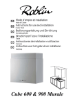
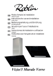
PROFIL Murale 900
NOTICE D’UTILISATION ET D’INSTALLATION
DIRECTIONS FOR USE AND INSTRUCTIONS FOR INSTALLATION
GEBRAUCHS- UND MONTAGEANWEISUNG
LIBRETTO DI ISTRUZIONI
INSTRUCCIONES DE UTILIZACION E INSTALACION
GEBRUIKS- EN MONTAGEHANDLEIDING
F
SOMMAIRE
1
GB
CONTENTS
5
RACCORDEMENT ÉLECTRIQUE
ELECTRICAL WIRING
CONSEILS D’INSTALLATIONS
INSTALLATION ADVICE
POSE DE L’APPAREIL
FITTING THE APPLIANCE
FONCTIONNEMENT
OPERATION
CONSEILS D’UTILISATIONS
USEFUL HINTS
ENTRETIEN
MAINTENANCE
GARANTIE ET SERVICE APRÈS-VENTE
GUARANTEE AND AFTER-SALES-SERVICES
REMARQUES
REMARKS
D
INHALT
11
I
CONTENUTI
NETZANSCHLUSS
COLLEGAMENTO ELETTRICO
MONTAGEHILFEN
CONSIGLI DI INSTALLAZIONE
MONTAGE DES GERÄTES
POSA DELL’ APPARECCHIO
BETRIEB DES GERÄTES
FUNZIONAMENTO
NUTZUNG
CONSIGLI DI UTILIZZO
WARTUNG UND REINIGUNG
MANUTENZIONE
GARANTIE UND KUNDENDIENST
GARANZIA ED ASSISTENZA TECNICA
WICHTIGE HINVEISE
NOTE
E
SUMARIO
21
NL
INHOUD
CONEXION ELECTRICA
ELECTRISCHE BEDRADING
CONSEJOS DE INSTALACION
MONTAGE AANWIJZING
INSTALACION DEL APARATO
AANSLUITEN VAN HET APPARAAT
FUNCIONAMIENTO
FUNKTIONEREN
CONSEJOS DE UTILIZACION
GEBRUIKSADVIES
MANTENIMIENTO
ONDERHOUD
GARANTIA Y ASSISTENCIA TECNICA
AFTER SALES SERVICE
NOTA
OPMERKINGEN
16
25
F
Nous vous remercions de la confiance que vous nous avez accordée en choisissant un appareil de la
gamme ROBLIN.
Celui-ci a fait l’objet de toute notre attention dans sa conception et sa réalisation.
Afin qu’il vous donne entière satisfaction, nous vous recommandons de lire avec attention cette notice
qui vous expliquera comment l’installer, l’utiliser et l’entretenir dans les meilleures conditions.
1
RACCORDEMENT ÉLECTRIQUE.
• La hotte est équipée d’un cordon d’alimentation de type HO5VVF 3 x 0,75 mm² comportant une
fiche normalisée 10/16 A avec système de mise à la terre.
Mode de protection : classe 1. Tension d’alimentation : 220-240 V mono - 50Hz / 220 V - 60Hz.
Vérifier que la tension du secteur est identique aux valeurs indiquées sur la plaque signalétique à l’intérieur de la hotte
• Si la hotte est raccordée directement sur le réseau sans sa fiche, un interrupteur omnipolaire avec
une ouverture de contact de 3 mm doit être installé avant la hotte. Le fil de terre (Jaune / vert) ne doit pas
être interrompu par cet interrupteur.
2
CONSEILS D’INSTALLATION.
• Pour un fonctionnement idéal, nous vous conseillons une plage de hauteur de pose qui se situe de
0,65 m à 0,70 m au-dessus du plan de cuisson. Toutefois, il est formellement interdit d’installer toute
hotte ou groupe d’aspiration à une distance inférieure à 0,65 m du plan de travail (risque d’inflammation
des filtres). La fumée doit monter naturellement vers la zone de captation.
• Respecter le diamètre de sortie de l’appareil : la hotte ne doit en aucun cas être raccordée à un
conduit de ventilation mécanique contrôlée (V.M.C.).
• Lorsqu’on évacue l’air vicié dans un conduit d’évacuation, veiller à ce que celui-ci ne soit pas déjà
exploité à véhiculer des gaz ou fumées provenant d’appareils alimentés par une énergie autre qu’électrique.
• Positionner le plan de cuisson au plus près de l’évacuation et éviter la formation de coudes sur la
gaine, afin de réduire au maximum les pertes de charges.
• Dans tous les cas d’installation, veiller au bon renouvellement d’air de la cuisine. Penser à effectuer
une ou des entrées d’air par une grille de section égale ou supérieure au diamètre du tuyau
d’évacuation, afin de ne pas mettre la cuisine en dépression.
• Prévoir une aération suffisante lorsqu’un appareil de cuisson ou autre utilise simultanément l’air
ambiant de la pièce où est installée la hotte.
• La dépression maximum crée dans la pièce doit être inférieure à 0.04 mbar, ce qui évite un retour de
gaz de combustion.
• L’appareil doit être positionné de telle façon que la fiche d’alimentation soit accessible.
3
POSE DE L’APPAREIL.
Montage et raccordement doivent être réalisés par un installateur* qualifié.
(*) Le non-respect de cette condition entraîne la suppression de la garantie du constructeur et
tout recours en cas d’accident.
1) Tracer une verticale à l’emplacement de la hotte (fig1, rep 1).
2) Fixer le support de conduit (2) à l’aide des vis TH 5 x 50 et des chevilles fournies.
3) Définir le bas de la hotte (rep 3) afin de fixer les supports au mur (fig 3, rep 4).
4) Accrocher le corps (rep 5) sur les supports muraux.
5) Raccorder le tuyau flexible à l’évacuation extérieure et la sortie de l’appareil (rep 6).
6) Parfaire le réglage d’alignement de l’ensemble, à l’aide des vis TH 5 x 25 des supports, ainsi que
l’inclinaison à l’aide des 2 vis 5 x 25 mm TC.F
7) Après avoir effectué tous les réglages d’alignement de l’ensemble de la hotte, verrouiller celle-ci par
une vis de fixation positive (rep 8), afin de garantir la sécurité d’accrochage.
8) Le conduit Rep. 7 est constitué de 2 parties. Emboîter le haut de conduit dans le bas de conduit
télescopique et fixer le sur le support (rep 2) par 2 vis M4 (fig 6).
1
F
• RECYCLAGE
Fixer le déflecteur avec le support de conduit (fig 2).
Le haut de conduit (avec les ouvertures visibles) doit coïncider avec la position du déflecteur.
Installer un tuyau de diamètre approprié entre la sortie de l’appareil et à l’entrée du déflecteur.
Placer les cartouches à charbon actif dans leurs logements en exerçant une pression sur les languettes
A (fig. 4).
4
FONCTIONNEMENT
a) Configuration
Evacuation extérieure ou recyclage :
Votre hotte est programmée pour fonctionner en mode évacuation extérieure. Si vous souhaitez l’utiliser en
mode recyclage, vous devez impérativement la configurer suivant la procédure suivante :
Mise en recyclage ( l’air est filtré puis renvoyé dans la cuisine) :
Moteur et éclairage éteints, appuyer sur la touche (+) jusqu’aux clignotements des 5 leds :
Deux clignotements des 5 leds indiquent l’enregistrement de la mise en recyclage.
Retour en mode évacuation ( L’air est filtré puis évacué à l’extérieur de l’habitation):
Moteur et éclairage éteints, appuyer sur la touche (+) jusqu’aux clignotements des 5 leds :
Un clignotement des 5 leds indiquera l’enregistrement de la mise en évacuation extérieure.
b) Fonctions de base :
Eclairage :
Mise en marche en appuyant sur la touche 1 (lumière). La led 1 visualise l’état de l’éclairage
Moteur :
Mise en marche en appuyant sur la touche 2 (moteur). Il est possible de modifier le débit d’aspiration de
la hotte à l’aide des touches vitesse + et vitesse – , en gardant la touche enfoncée jusqu’à l’obtention de
la vitesse désirée. Le niveau de vitesse est visualisé par les leds 2, 3, 4 qui s’allument au fur et à mesure
de l’accroissement de la vitesse :
Led 2
= niveau minimum
Led 2 et 3 = niveau intermédiaire
Led 2, 3 et 4 = niveau élevé
Un débit d’aspiration maximal peut être obtenu directement en appuyant sur la touche vitesse intensive
(5 ).F
c) Fonctions complémentaires :
• Vitesse intensive temporisée
Pour obtenir une bonne efficacité d’évacuation, nous vous conseillons en début de cuisson une période de
fonctionnement en position intensive. Elle créera un flux d’air permettant de capter les premières fumées
ou vapeurs dès leur apparition. Pour cette fonction il convient de suivre la procédure suivante :
- Mettre le moteur en marche (touche 2), puis sélectionner à l’aide des touches (+) et (-) la vitesse souhaitée
pendant la cuisson.
- Appuyer sur la touche 5 (vitesse intensive). Cette fonction peut être arrêtée en appuyant à nouveau sur
la touche 5.
2
F
Temporisation de 5 minutes de l’arrêt de la vitesse intensive:
Par défaut cette fonction n’est pas activée.
Pour accéder à la programmation de cette fonction, la lumière doit être éteinte et le moteur arrêté.
Appuyer sur la touche réglage vitesse (-) :
Un clignotement des Leds 2, 3, et 4 = fonction désactivée.
Deux clignotements des Leds 2, 3, et 4 = fonction activée.
Il est possible d’arrêter manuellement la vitesse intensive avant le délai de 5 minutes en appuyant à nouveau
sur la touche 5 (Vitesse intensive).
Pendant cette temporisation de 5 minutes, l’indication de saturation filtres est désactivée.
Si un arrêt différé de la hotte est programmé, la vitesse intensive commandée manuellement ou temporisée
sera désactivée par cet arrêt différé après 5, 10 ou 15 minutes. Il est possible d’arrêter manuellement la vitesse intensive avant l’arrêt différé de la hotte en appuyant à nouveau sur la touche 5 (Vitesse intensive).
• Arrêt différé :
Cette fonction permet, après l’arrêt de la cuisson, d’évacuer les dernières fumées et odeurs résiduelles
et en fin de cuisson, d'arrêter totalement la hotte (moteur + éclairage).
Pour accéder à la programmation de ce réglage la lumière doit être éteinte et le moteur arrêté.
Appuyer sur la touche vitesse intensive 5 :
- 2 clignotements des leds 1 & 5 confirmeront l’enregistrement de l’arrêt après 5 minutes.
- 3 clignotements des leds 1 & 5 confirmeront l’enregistrement de l’arrêt après 10 minutes.
- 4 clignotements des leds 1 & 5 confirmeront l’enregistrement de l’arrêt après 15 minutes.
- 1 seul clignotement des leds 1 & 5 confirmera la suppression de la fonction arrêt différé.
La hotte peut ensuite être mise en marche sur la vitesse choisie. Le clignotement des leds 2, 3, 4 (suivant
la vitesse initialement prévue) indiquera que la fonction arrêt différé est bien programmée :
- 1 clignotement = arrêt après 5 minutes
- 2 clignotements = arrêt après 10 minutes
- 3 clignotements = arrêt après 15 minutes
• Indication de saturation des filtres métalliques :
Après 200 heures de fonctionnement 1 bref clignotement de la Led 1 indique qu’il faut nettoyer les
filtres métalliques (voir paragraphe entretien)
Pour accéder à la remise à zéro de la fonction indiquant la saturation des filtres, la lumière doit être
éteinte et le moteur arrêté.
Appuyer sur la touche (+) pendant 3 à 4 secondes. Le clignotement des Leds 1, 2, 3, 4, et 5 confirme la
remise à zéro.
• Indication de saturation des filtres charbon :
Après 400 heures de fonctionnement 2 brefs clignotements de la Led 1 indique qu’il faut remplacer
les filtres charbon et nettoyer à nouveau les filtres métalliques.
Pour activer la fonction Indication de saturation filtre charbon, la lumière doit être éteinte et le moteur
arrêté. Appuyer sur la touche (+) pendant 10 secondes.
1 clignotement des Leds 1, 2, 3, 4, et 5 = fonction désactivée.
2 clignotements des Leds 1, 2, 3, 4, et 5 = fonction activée.
La méthode de remplacement de la cartouche est indiquée au paragraphe 3 (Recyclage)
• Configuration réception télécommande :
Votre hotte est programmée pour fonctionner sans réception télécommande. Si vous souhaitez l’utiliser avec
la télécommande, vous devez impérativement la configurer suivant la procédure suivante :
Moteur et éclairage éteints, appuyer sur la touche 1 (éclairage) jusqu’au clignotement de la led 1 :
Deux clignotements de la led 1 indiquent que la télécommande est activée.
Un clignotement de la led 1 indique que la télécommande est désactivée.
Attention, la télécommande doit être équipée de piles alcalines standards : LR003-AAA, 1.5V comme décrit
Fig. 5. Ces piles devraient assurer un usage optimum de longue durée et doivent être positionnées correctement, elles peuvent exploser si elles sont endommagées ou exposées à la chaleur. Ne pas les jeter dans
3
F
le feu. Afin de préserver l’environnement, merci de déposer ces piles dans un conteneur approprié.
5
CONSEILS D’UTILISATION
• Pour obtenir une efficacité maximum d’absorption des fumées ou des vapeurs, faire fonctionner
l’appareil 5 minutes environ avant et après la cuisson des aliments; La première vitesse est conseillée
pour les cuissons à feu doux et pour les sauces. La deuxième pour les cuissons soutenues, grillades et
friteuses. La troisième est indiquée pour les cuissons à forte émanation de graisses et vapeur.
• IMPORTANT . NE JAMAIS FLAMBER DE METS AU DESSOUS DE L’APPAREIL
Ne laissez jamais de flammes libres sous la hotte en fonctionnement.
• Les fritures nécessitent une surveillance permanente, l’huile surchauffée pouvant s’enflammer.
6
ENTRETIEN
Déconnecter le câble d’alimentation pour toute intervention électrique.
L’appareil a été conçu pour faciliter au maximum les opérations d’entretien, synonyme de bon fonctionnement et rendement de l’appareil dans le temps.
• Nettoyage des filtres métalliques.
Il est indispensable de procéder à un NETTOYAGE PÉRIODIQUE de ces filtres à la main (avec un
détergent liquide à l’eau tiède et rinçage) ou au lave- vaisselle (tous les deux mois environ pour une
utilisation normale).
• Carrosserie.
Nettoyer régulièrement celle-ci en utilisant des produits détergents, non abrasifs et une éponge légèrement humide. N’utilisez jamais d’éponges ou de chiffons trempés.
N’introduisez aucun objet, ni les mains dans l’ouverture servant à l’évacuation de l’air.
• Conduit d’évacuation.
Vérifier tous les 6 mois le bon écoulement de l’air vicié.
Observer les prescriptions réglementaires locales concernant l’évacuation de l’air vicié.
• Éclairage.
Avant toute intervention sur l’appareil, mettre l’interrupteur d’allumage des lampes en position éteinte.
Ne pas dépasser la puissance prescrite et ne pas changer de type de lampe.
7
GARANTIE ET SERVICE APRÈS-VENTE
• En cas d’anomalie de fonctionnement, prévenez votre installateur qui devra vérifier l’appareil et son
raccordement.
• Dans le cas où un composant électrique viendrait à être endommagé, celui-ci ne peut être remplacé
que par un atelier de réparation reconnu par le fabricant, car des outils spéciaux sont nécessaires.
• Débrancher complètement l’appareil.
• Exigez toujours l’utilisation de pièces de rechange d’origine. La non observation de cette prescription
peut compromettre la sécurité de l’appareil.
• Lors de la commande de pièces détachées, rappeler le numéro de l’appareil inscrit sur la plaque
signalétique située à l’intérieur de la hotte.
• Seule la facture d’achat de l’appareil fera foi pour l’application de la garantie contractuelle.
Cette garantie ne couvre pas les consommables comme :
- L’éclairage : lampes incandescentes, halogènes ...
- Les filtres.
8
REMARQUES
Nos appareils sont conformes aux normes harmonisées CEI 335 et aux directives européennes basse
tension 73/23 et compatibilité électromagnétique 89/336.
4
GB
Thank you for buying a Roblin product which has been manufactured to the highest quality standards to
meet your requirements.
We recommend you carefully read this booklet in which you will find instructions for installation, hints for
use and maintenance.
1
ELECTRICAL
• This cooker hood is fitted with a 3-core mains cable with a standard 10/16A earthed plug.
• Alternatively the hood can be connected to the mains supply via a double-pole switch having 3mm
minimum contact gap on each pole.
• Before connecting to the mains supply ensure that the mains voltage corresponds to the voltage on
the rating plate inside the cooker hood.
• Technical Specification: Voltage 220-240, single phase ~50Hz / 220 V - 60Hz.
2
INSTALLATION ADVICE
• Ensure the cooker hood is fitted in compliance with the recommended fixing heights.
• To ensure the safe operation of this cooker hood, we recommend that the hood should not be fitted
below 65cm (for electric) or (70cm for gas) the measurements taken from the surface of the cooking
appliance to the underside of the cooker hood.
• It is a possible fire risk if the hood is not sited as recommended.
• To ensure the best results, the cooking fumes should be able to rise naturally towards the inlet grilles
on the underside of the cooker hood and the cooker hood should be positioned away from doors and
windows, which will create turbulence.
• Ducting
• If the room where the hood is to be used contains a fuel-burning appliance such as a central heating
boiler then its flue must be of the room sealed or balanced flue type.
• If other types of flue or appliances are fitted ensure that there is an adequate supply of fresh air to the
room. Ensure the kitchen is fitted with an airbrick, which should have a cross-sectional measurement
equivalent to the diameter of the ducting being fitted, if not larger.
• The ducting system for this cooker hood must not be connected to any existing ventilation system,
which is being used for any other purposes or to a mechanically controlled ventilation ducting.
• The ducting used must be made from fire retardant materials and the correct diameter must be used,
as incorrect sized ducting will affect the performance of this cooker hood.
• When the cooker hood is used in conjunction with other appliances supplied with energy other than
electricity, the negative pressure in the room must not exceed 0.04 mbar to prevent the fumes from
combustion being drawn back into the room.
• The appliance is for domestic use only and should not be operated by children or people who are
infirm without supervision.
• This appliance must be positioned so that the wall socket is accessible.
3
FITTING
Any permanent electrical installation must comply with the latest regulations concerning this type of
installation and a qualified electrician must carry out the work. Non-compliance could cause serious
accidents or injury and would deem the manufacturers guarantee null and void.
IMPORTANT - The wires in this mains lead are coloured in accordance with the following code :
- green / yellow : earth
- blue : neutral
- brown : live
As the colours of the wires in the mains lead of this appliance may not correspond with the coloured
markings identifying the terminals in your plug, proceed as follows.
- The wire which is coloured green and yellow must be connected to the terminal in the plug which is
marked with the letter E or by the earth symbol or coloured green or green and yellow.
- The wire which is coloured blue must be connected to the terminal which is marked with the letter N or
coloured black.
- The wire which is coloured brown must be connected to the terminal which is marked with the letter L or
5
GB
coloured red.GB
1) Draw a vertical line up the wall from the centre of the cooking appliance below as illustrated in
fig. 1 - item 1.
2) Draw a horizontal line through the vertical at 650 + item A when fitting above an electric hotplate or
at 700 + item A when fitting above a gas hotplate as illustrated in fig. 1.
3) Mark the hole centres for the canopy fixing brackets item 4 at item B mm as illustrated in fig. 3.
4) Draw a horizontal line through the vertical 40 mm from the ceiling or from the point where the chimney
will terminate.
5) Mark the hole centres for the upper chimney fixing bracket (item 2) at item C (fig. 1).
6) Drill the holes for the three fixing brackets using an 8 mm masonry bit.
7) Fix the brackets item 4 for canopy using the 5 x 50 mm hexagonal screws and rawl plugs supplied.
8) Fix the chimney support bracket (item 2) using the No 5 x 50mm hexagonal headed screws and rawl
plugs supplied.
9) Hook the canopy item 5 onto the wall brackets item 4 as illustrated in fig. 3.
10) To ensure the cooker hood is aligned correctly adjust the screws on the top of the canopy as illustrated
in fig. 3.
11) When the hood is aligned correctly mark the hole centre on the wall for the security fixing screw item
8, which is located in the right hand bracket on the top of the canopy.
12) Unhook the canopy from the wall and drill the hole for the security fixing screw.
13) Hook the canopy onto the wall and fix the No 5 x 50mm headed screw and rawl plug to secure the
canopy to the wall.
14) Connect the ducting to the spigot item 6.
15) Place the telescopic chimney item 7 onto the canopy and extend the upper chimney section around
the chimney support bracket item 2 and fix the chimney to the bracket using the two No 4 x 8mm self
tapping screws as illustrated in fig. 6.
• RECYCLING
The hood is easily converted to the recycling mode by installing the recycling ducting adapter item A, a
short length of 150mm ducting and a charcoal filter (optional).
1) Fix the recycling ducting adapter to the chimney support bracket item 2 as illustrated in fig. 2 while
connecting a cut length of 150mm round ducting between the recycling ducting adaptor and the ducting
spigot item 6 on top of the canopy item 5.
2) Remove the metal grease filters and insert the charcoal filter into the base of the motor housing and
secure the filter with two metal securing straps item A as illustrated in fig. 4.
4
OPERATION
A - EXTRACTION OR RECYCLING :Your cooker hood is supplied in the extraction mode. To use the cooker
hood in the recycling mode re-programme the hood as follows:
Starting in the recycling mode (the contaminated air passes into the hood through the grease filters and
the purifying activated charcoal filter and back out into the kitchen through grilles).
Press the ‘+’ button (while the motor and lights are switched ‘OFF’) until the five LED lights will flash twice
to indicate confirmation that the cooker hood is in the recycling mode.
6
GB
Reverting to the extraction mode (The cooker hood is ducted to the outside).
Press the ‘+’ button (while the motor and lights are switched ‘OFF’) until the five LED lights will flash once
to indicate confirmation that the cooker hood is in the extraction mode.
GB
B - BASIC INSTRUCTIONS
Lighting
Press LED button 1 to switch ‘ON’ the lights and the LED will illuminate to confirm the lights are switched
‘ON’.
Motor
Press LED button 2 to switch ‘ON’ the fan motor (and adjust the speed of the fan motor by pressing the
LED button ‘+’ and ‘-‘) and the LED lights 2, 3 and 4 will illuminate. The fan speed will be increased if
constant pressure is kept on the (+) button.
LED 2
: Minimum speed - cooking with one pan or simmering
LED 2 & 3 : Medium speed - normal cooking with up to 4 pans
LED 2, 3 & 4 : Maximum speed - frying and cooking foods with strong odours
Press LED button 5 to obtain the boost position for maximum effect and the LED will illuminate to confirm
fan is switched ‘ON’.
C - COMPLEMENTARY INSTRUCTIONS
• Boost speed :
To obtain the best performance it is advisable to switch ‘ON’ the cooker hood a few minutes (in the boost
setting) before you start cooking. To program the complementary function, proceed as follows:
- Press LED button 2 to switch ‘ON’ the fan motor and adjust the speed of the fan by pressing the LED
button ‘+’ and ‘-‘. You should keep applying pressure to the ‘+’ and ‘-‘ button until the required speed is
selected.
- Press LED button 5 (boost speed) to switch ‘ON’ the fan motor in the boost setting. Press LED button 5
to switch ‘OFF’ the boost setting immediately.
It is advisable too that you should leave it running in the boost setting for approximately 5 minutes after
finishing.
• Pre-set stop of the boost speed :
A pre-set stop after 5 minutes of the boost speed is available.
Your cooker hood is supplied with a deactivated pre-set stop of the boost speed. To use the cooker hood
with a pre-set stop of the boost speed re-programme the hood as follows:
The lights and the fan motor should be switched ‘OFF’ to set the timer.
Push the LED button ‘-’ until the LED lights will flash :
One flash of the LED lights 2,3, and 4 = function is switched ‘OFF’.
Two flashes of the LED lights 2,3, and 4 = function is switched ‘ON’.
While the 5 minutes timer is running, It is available to stop immediately the boost speed by pressing the
led button 5.
While the 5 minutes timer is running, the indication of saturation of the filters is switched ‘OFF’.
If a pre-set stop for the hood is switched ‘ON’ and the 5 minutes timer is still running, the boost speed will
be switched ‘OFF’ together with the pre-set stop for the hood after the count down of 5, 10 or 15 minutes.
It is available to stop the boost speed before the count down of the preset stop of the hood by pressing
the led button 5.
• Pre-set stop for the hood :
This function allows you to program the cooker hood to automatically stop cooking after a pre-set period.
The lights and the fan motor should be switched ‘OFF’ to set the timer.
Proceed by repeatedly pressing the LED button 5 (Boost speed):
Two flashes of the LED button 1 & 5 = 5 minutes delay.
Three flashes of the LED button 1 & 5 = 10 minutes delay.
Four flashes of the LED button 1 & 5 = 15 minutes delay.
7
GB
One flash of the LED button indicates the function is switched ‘OFF’.
You can switch the cooker hood ‘ON’ and adjust the speed. The LED buttons 2, 3 and 4 will flash to
indicate the fan motor is switched ‘ON’ and which speed has been selected.
One flash = stop after 15 minutes.
Two flashes = stop after 10 minutes.
Three flashes = stop after 15 minutes.
• Indication of saturation of the metal grease filters :
After 200 hours use, one quick flash of the LED 1 will indicate that you must clean the metal grease
filters. (See chapter on ‘Maintenance’).
To reset the 200 hours timer back to zero requires the motor and lights must be switched ‘OFF’; then and
proceed as follows:
Press the LED button ‘+’ for 3 to 4 seconds and the LED lights 1,2,3, 4 and 5 will flash to confirm the
programme has been reset to zero.
8GB
• Indication of saturation of the active charcoal filter :
After 400 hours use, two quick flash of the LED 1 will indicate that you must replace the active charcoal
filter and clean the metal grease filters. (See chapter on ‘Maintenance’).
To reset the 400-hour timer the motor and lights must be switched ‘OFF’.
Push the LED button ‘+’ for 10 seconds.
One flash of the LED lights 1,2,3,4 and 5 = function is switched ‘OFF’.
Two flashes of the LED lights 1,2,3,4 and 5 = function is switched ‘ON’.
Instructions for replacing the active charcoal filter are given in the chapter on ‘Recycling’.
• Pre-set remote control handset
Your cooker hood is supplied with a deactivated remote control receiver. To use the cooker hood with a
remote control re-programme the hood as follows:
Press the LED button (Lighting) ‘1’ while the motor and lights are switched ‘OFF’, until the LED lights 1 will
flash to confirm the programme has been activated :
One flash of the LED lights 1 = function is switched ‘OFF’.
Two flashes of the LED lights 1 = function is switched ‘ON’.
Caution, the remote control handset must be fitted with standard LR03-AAA size 1.5V zinc-carbon alkaline
batteries as illustrated Fig. 5. These batteries should give a long life and constant discharge throughout their
life. These batteries must be disposed of properly and could explode if damaged or exposed to heat.
Do not dispose of on fire. Dispose of batteries in the appropriate sort container to protect the environment.
• Setup Process
Modification: How to adjust the internal microprocessor data to suit the type of motor fitted to this
appliance and the supply frequency of 50 or 60 Hz..
1 - Disconnect the cooker hood from the mains supply.
2 - Push the button 0/1 MOTOR.
3 - Reconnect the mains supply while pushing the button 0/1 MOTOR for at least 2 seconds.
4 - Release the button 0/1 MOTOR (the Leds flash for about 3 seconds : capacity’s confirmation SETUP
PROCESS).
5 - While the LED is flashing select the motor type used while pushing one of the 5 buttons in accordance
with the following:
BUTTON 0/1 Light : Motor EBM PRO 220-240 V AC 50 Hz / 220 V AC 60 Hz.
BUTTON 0/1 Motor : Motor FABER 8/28 e 8/50 220-240 V AC 50 Hz / 220 V AC 60 Hz.
BUTTON Speed ( - ) : Motor EBM MISTRAL 220-240 V AC 50 Hz / 220 V AC 60 Hz.
BUTTON Speed (+ ) : Motor EBM PRO 220-240 V AC 50 Hz / 220 V AC 60 Hz.
8
GB
BUTTON Intensive speed : Motor FABER K40-K50 220-240 V AC 50 Hz / 220 V AC 60 Hz.
N.B. : If you have not selected a motor type while the LED is flashing the microprocessor will automatically
select the default motor EBM PRO 220 - 240 V AC 50 Hz / 220 V AC 60 Hz.
5
USEFUL HINTS
• To obtain the best performance it is advisable to switch ‘ON’ the cooker hood a few minutes (in the
boost setting) before you start cooking and you should leave it running for approximately 15 minutes after
finishing.
• IMPORTANT: NEVER DO FLAMBÉ COOKING UNDER THIS COOKER HOOD
• Do not leave frying pans unattended during use as over-heated fat and oil might catch fire.
• Do not leave naked flames under this cooker hood.
• Switch ‘OFF’ the electric and gas before removing pots and pans.
• Ensure heating areas on your hotplate are covered with pots and pans when using the hotplate
and cooker hood simultaneously.
6
MAINTENANCE
Before carrying out any maintenance or cleaning isolate the cooker hood from the mains supply.
The cooker hood must be kept clean; a build up of fat or grease can be a fire hazard.
Casing
• Wipe the cooker hood frequently with a clean cloth, which has been immersed in warm water containing
a mild detergent and wrung out.
• Never use excessive amounts of water when cleaning particularly around the control panel.
• Never use scouring pads or abrasive cleaners.
• Always wear protective gloves when cleaning the cooker hood.
Metal Grease Filters
The metal grease filters absorb grease and dust during cooking to help keep the cooker hood clean
inside. The grease filters should be cleaned once a month or more frequently if the hood is used for more
than 3 hours per day.
To remove and replace the metal grease filters
• Remove the metal grease filters one at a time by releasing the catches on the filters; the filters can
now be removed.
• The metal grease filters should be washed, by hand, in mild soapy water or in a dishwasher.
• Allow to dry before replacing.
Active Charcoal Filter
The charcoal filter cannot be cleaned. The filter should be replaced at least every three months or more
frequently if the hood is used for more than three hours per day.
To remove and replace the filter
• Remove the metal grease filters.
• Press against the two retaining clips, which hold the charcoal filter in place and this will allow the filter
to drop down and be removed.
• Clean the surrounding area and metal grease filters as directed above.
• Insert the replacement filter and ensure the two retaining clips are correctly located.
• Replace the metal grease filters.
Extraction tube.
Check every 6 months that the dirty air is being extracted correctly. Comply with local rules and regulations with regard to the extraction of ventilated air.
Lighting.
If the lamp fails to function check to ensure it is fitted correctly into the holder. If lamp failure has occurred
then it should be replaced with identical replacement.
Do not replace with any other type of lamp and do not fit a lamp with a higher rating.
9
GB
7
GUARANTEE AND AFTER SALES SERVICE
• In the event of any malfunction or anomaly, notify your fitter who will have to check the appliance and its connection.
• In the event of damage to the mains supply cable, this can only be replaced by at approved repair
centre appointed by the manufacturer who have the necessary tools and equipment to carry out any
repairs properly. Repairs carried out by other persons will invalidate the guarantee.
• Use only genuine spare parts. Should these warnings fail to be observed it could affect the safety of
your cooker hood.
• When ordering spare parts quote the model number and serial number written on the rating plate,
which is found on the casing behind the grease filters inside the hood.
• Proof of purchase will be required when requesting service. Therefore, please have your receipt
available when requesting service as this constitutes the date from which your guarantee commenced.
This Guarantee does not cover :
- Damage or calls resulting from transportation, improper use or neglect, the replacement of any light
bulbs or filters or removable parts of glass or plastic.
These items are considered to be consumable under the terms of this guarantee.
8
REMARKS
Your appliance comply with harmonised standards CEI 335 and the Europeans’ directives (Low voltage)
73/23 and ( Electromagnetic compatibility ) 89/336.
10
Plaque Signalétique de la hotte
Rating plate of the cookerhood
Typenschild im Inneren der Dunstesse
Etichetta all'interno della cappa
Etiqueta de la campana
Typeplaatje van de afzuigkap
Modèle
Model
Modell
Modello
Modelo
Model
Numéro de série
Serial number
Seriennummer
Numero di serie
Numero de serie
Serienummer
29
Composants
Components
Bauelemente
Componenti
Componentes
Onderdelen
2
7
R
4
5
8
6
30
1
258,5
7
2
6
1
8
4
30
250
312
H mini 650 mm
423
30
5
3
2
2
40
2
258,5
31
3
312
4
30
250
4
A
32
3
5
LR03 / AAA / 1,5V
1
2
325
R 800
R 300
90
691 - 910
362
270
404
500
898
33
B
A
C
E
34
D
F
F
H
G
J
I
K
L
35
M
Purple
Pink
L
M
ECLAIRAGE HALOGENE
HALOGEN LIGHTING
HALOGEN BELEUCHTUNG
2 x 50 W - 230 V
Black
White
Brown
Blue
L F
N
10 µF
400 V
220 - 60Hz
FERNBEDIENUNG
RECEPTEUR INFRAROUGE
REMOTE CONTROL
Green-Yellow
M
350 W
220 - 240 V 50Hz
ELEKTRONISCHE STEUERUNG
BOITIER COMMANDE
PUSH BUTTON PANEL
AZUR - AZUR - AZUR BLAU
BLACK - NOIR- SCHWARZ
BLUE - BLEU - BLAU
BROWN - BRUN - BRAUN
GREEN YELLOW - VERT JAUNE - GRÜN GELB
GREY - GRIS - GRAU
LIGHT BLUE - BLEU CLAIR - HELL BLAU
PINK - ROSE - ROSA
PURPLE - MAUVE - MALVER FARBIG
WHITE - BLANC - WEISS
YELLOW - JAUNE - GELB
MULTI-FLACH KABEL
LIMANDE COMMANDE
FLAT CABLE
Yellow
Black
Grey
White
Azur
Brown
Light-Blue
Brown
Green-Yellow
Profil Murale 900
depuis : Avril 2006
( From)
3S_Profil_M_90_V2006-04
MAJ (UPDATE) : 29/03/06
Page 1/1
66
ACCESSOIRES
ACCESSORIES
ZUBEHÖRE
ACCESSORI
ACCESORIA
ACCESSOIRES
GU10
50 W - 230 V
Code 12EC006
37
F - Votre produit est conçu et fabriqué avec des matériaux et des composants
de haute qualité, qui peuvent être recyclés et utilisés de nouveau.
Lorsque ce symbole d’une poubelle à roue barrée est attaché à un produit,
cela signifie que le produit est couvert par la Directive Européenne 2002/96/EC.
Veuillez vous informer du système local de séparation des déchets électriques
et électroniques.
Veuillez agir selon les règles locales et ne pas jeter vos produits usagés avec
les déchets domestiques usuels. Jeter correctement votre produit usagé aidera à prévenir les
conséquences négatives potentielles contre l’environnement et la santé humaine.
GB - Your product is designed and manufactured with high quality materials and components,
which can be recycled and reused.
When this crossed-out wheeled bin symbol is attached to a product it means the product is
covered by the European directive 2002/96/EC.
Please inform yourself about the local separate collection system for electrical and electronic
product.
Please act according to your local rules and do not dispose of your old products with your
normal household waste. The correct disposal of your old product will help prevent potential
negative consequences for the environment and human health.
D - Ihr Produkt ist au hochqualitativen Materialien und Bestandteilen hergestellt, die dem
Recycling zugefürht und wiederverwertet werden können.
Falls dieses Symbol eines durchgestrichchenen Müllcontainers auf Rollen auf diesem Produkt
angebracht ist, bedeutet dies, dass es von der Europäischen Richtlinie 2002/96/EG erfasst wird.
Bitte informieren Sie sich über die örtlichen Sammelstellen für Elektroprodukte und elektronische
Geräte.
Bitte beachten Sie die lokalen Vorschriften und entsorgen Sie Ihre Altgeräte nicht mit dem
normalen Haushaltsmüll. Die korrekte Entsorgung Ihres Altgerätes ist ein Beitrag zur Vermeidung möglicher negativer Folgen für die Umwelt und die menschliche gesundhei.
I - Questo prodotto è stato progettato e fabbricato con materiali e componenti di alta qualità, che
posssono esere riciclati e riutilizzati.
Quando ad un prodotto è attaccato il simbolo del bidone con le ruote segnato da una croce,
significa che il prodotto è tutelato dalla Directiva Europea 2003/96/EC.
Si prega di informarsi in merito al sistema locale di raccolta differenziata per i prodotti elettrici ed
elettronici.
Rispettare le norme locali in vigore e non smaltire i prodotti vecchi nei normali rifiuti domestici. Il
correto smaltimento del prodotto aiuta ad evitare possibili conseguenze negative per la salute
dell’ambiente e dell’uomo.
E - Su producto ha sido diseñado y fabricado con materiales y componentes de alta calidad,
que pueden ser reciclados y reutilizados.
Cuando vea este símbolo de una papelera con ruedas tachada junto a un producto, esto significa
que el producto está bajo la Directiva Europea 2002/96/EC.
Deberá informarse sobre el sistema de reciclaje local separado para productos eléctricos y
electrónicos.
Siga las normas locales y no se deshaga de los productos usados tirándolos en la basura normal
de su hogar. El reciclaje correcto de su producto usado ayudará a evitar consecuencias negativas
para el medio ambiente y la salud de las personas.
NL - Uw apparaat werd ontworpen met en vervaardigd uit onderdelen en materialen van
superieure kwaliteit, die gerecycleerd en opnieuw gebruikt kunnen worden.
Wanneer het symbool van een doorstreepte vuilnisemmer op wielen op een product is bevestigd,
betekent dit dat het product conform is de Europese Richtlijn 2002/96/EC.
Gelieve u te informeren in verband met het plaatselijke inzamelingsysteem voor elektrische en
elektronische apparaten.
Gelieve u te houden aan de plaatselijke reglementering en apparaten niet met het gewone huisvuil
mee te geven.
Door afgedankte apparaten op een correcte manier weg te werpen help u mogelijke negatieve
gevolgen voor het milieu en de gezondheid te voorkomen.
Cet équipement est conforme à la norme européenne sur la basse tension C.E.E. 73/23 relative
à la sécurité électrique et aux normes européennes: C.E.E. 89/336 relative à la compatibilité
électromagnétique et C.E.E. 93/68 relative au marquage CE.
This appliance complies with European regulations on low voltages, EEC Directive 73/23 on
electrical safety, and with the following European regulations: EEC Directive 89/336 on
electromagnetic compatibility and EEC Directive 93/68 on EC marking.
Dieses Gerät entspricht den europäischen Niederspannungsrichtlinien 73/23/EWG zur
elektrischen Sicherheit, den europäischen Richtlinien 89/336/EWG zur elektromagnetischen
Verträglichkeit und den Richtlinien 93/68/EWG zur CE-Kennzeichnung
Quest’apparecchio é conforme alla norma europea sulla bassa tensione C.E.E. 73/23 relativa
alla sicurezza elettrica e alle norme europee: C.E.E. 89/336 relativa alla compatibilità elettromagnetica e C.E.E. 93/68 relativa alla marcatura CE.
Este aparato esta en conformidad con la norma europea en relación con baja tensión C.E.E 73/
23 de la securidad electrica y a las normas europeas C.E.E 89/336 en relatión con la compatibilad
electromagnetica y C.E.E 93/68 en relación con la marcación CE.
Dit apparaat voldoet aan de Europese Laagspanningsrichtlijn 72/23/EEG inzake de elektrische
veiligheid en aan de Europese normen 89/336/EEG inzake de elektromagnetische compatibiliteit
en 93/68/EEG inzake de CE-markering.
ROBLIN S.A. - Route de Caen - Sainte Cécile - B. P. 56 - 50800 VILLEDIEU-LES-POËLES - France
Tél. 02 33 91 26 50 - Fax 02 33 51 54 79 - e-mail : [email protected]
For outside France : Tel. +33 (0)2 33 91 26 57 - Fax. +33 (0)2 33 51 54 79
e-mail : [email protected]
20NO140 - 060419