1
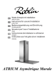
FR
Mode d’emploi et installation
GB
Instructions for use and installation
DE
Bedienungsanleitung und Einrichtung
IT
Istruzioni per l’uso e l’installazione
E
Instrucciones de instalacion e utilizacion
NL
NL
Instructies voor het gebruik en installeren
Hotte de Cuisine
Cooker Hood
Dunstabzugshaube
Cappa
Campana
Dampkap
Vizio/3 Murale Verre
F
SOMMAIRE
GB
CONTENTS
RACCORDEMENT ÉLECTRIQUE
ELECTRICAL WIRING
CONSEILS D’INSTALLATIONS
INSTALLATION ADVICE
POSE DE L’APPAREIL
FITTING THE APPLIANCE
FONCTIONNEMENT
OPERATION
CONSEILS D’UTILISATIONS
USEFUL HINTS
ENTRETIEN
MAINTENANCE
GARANTIE ET SERVICE APRÈS-VENTE
GUARANTEE AND AFTER-SALES-SERVICES
REMARQUES
REMARKS
D
I
INHALT
CONTENUTI
NETZANSCHLUSS
COLLEGAMENTO ELETTRICO
MONTAGEHILFEN
CONSIGLI DI INSTALLAZIONE
MONTAGE DES GERÄTES
POSA DELL’ APPARECCHIO
BETRIEB DES GERÄTES
FUNZIONAMENTO
NUTZUNG
CONSICLI DI UTILIZZO
WARTUNG UND REINIGUNG
MANUTENZIONE
GARANTIE UND KUNDENDIENST
GARANZIA ED ASSISTENZA TECNICA
WICHTIGE HINVEISE
NOTE
E
NL
SUMARIO
INHOUD
CONEXION ELECTRICA
ELECTRISCHE BEDRADING
CONSEJOS DE INSTALACION
MONTAGE AANWIJZING
INSTALACION DEL APARATO
AANSLUITEN VAN HET APPARAAT
FUNCIONAMIENTO
FUNKTIONEREN
CONSEJOS DE UTILIZACION
GEBRUIKSADVIES
MANTENIMIENTO
ONDERHOUD
GARANTIA Y ASSISTENCIA TECNICA
AFTER SALES SERVICE
NOTA
OPMERKINGEN
F
Nous vous remercions de la confiance que vous nous avez accordée en choisissant un appareil de la
gamme ROBLIN.
Celui-ci a fait l’objet de toute notre attention dans sa conception et sa réalisation.
Afin qu’il vous donne entière satisfaction, nous vous recommandons de lire avec attention cette notice
qui vous expliquera comment l’installer, l’utiliser et l’entretenir dans les meilleures conditions.
La présente notice d’emploi vaut pour plusieurs versions de l’appareil. Elle peut contenir des descriptions
d’accessores ne figurant pas dans votre appareil.
1
RACCORDEMENT ÉLECTRIQUE.
• La hotte est équipée d’un cordon d’alimentation de type HO5VVF 3 x 0,75 mm² comportant une
fiche normalisée 10/16 A avec système de mise à la terre.
Mode de protection : classe 1. Tension d’alimentation : 220-240 V mono - 50/60Hz.
Vérifier que la tension du secteur est identique aux valeurs indiquées sur la plaque signalétique à l’intérieur de la hotte
• Si la hotte est raccordée directement sur le réseau sans sa fiche, un interrupteur omnipolaire avec
une ouverture de contact de 3 mm doit être installé avant la hotte. Le fil de terre (Jaune / vert) ne doit pas
être interrompu par cet interrupteur.
2
CONSEILS D’INSTALLATION.
• Pour un fonctionnement idéal, nous vous conseillons une plage de hauteur de pose qui se situe de
0,65 m à 0,70 m au-dessus du plan de cuisson. Toutefois, il est formellement interdit d’installer toute
hotte ou groupe d’aspiration à une distance inférieure à 0,65 m du plan de travail (risque d’inflammation
des filtres). La fumée doit monter naturellement vers la zone de captation.
• Respecter le diamètre de sortie de l’appareil : la hotte ne doit en aucun cas être raccordée à un
conduit de ventilation mécanique contrôlée (V.M.C.).
• Lorsqu’on évacue l’air vicié dans un conduit d’évacuation, veiller à ce que celui-ci ne soit pas déjà
exploité à véhiculer des gaz ou fumées provenant d’appareils alimentés par une énergie autre qu’électrique.
• Positionner le plan de cuisson au plus près de l’évacuation et éviter la formation de coudes sur la
gaine, afin de réduire au maximum les pertes de charges.
• Dans tous les cas d’installation, veiller au bon renouvellement d’air de la cuisine. Penser à effectuer
une ou des entrées d’air par une grille de section égale ou supérieure au diamètre du tuyau
d’évacuation, afin de ne pas mettre la cuisine en dépression.
• Prévoir une aération suffisante lorsqu’un appareil de cuisson ou autre utilise simultanément l’air
ambiant de la pièce où est installée la hotte.
• La dépression maximum crée dans la pièce doit être inférieure à 0.04 mbar, ce qui évite un retour de
gaz de combustion.
• L’appareil doit être positionné de telle façon que la fiche d’alimentation soit accessible.
• Cet appareil ne doit pas être utilisé par des personnes (y compris les enfants) ayant des capacités psychiques, sensorielles ou mentales réduites, ni par des personnes n’ayant pas l’expérience et la connaissance de ce type d’appareils, à moins d’être sous le contrôle et la formation de personnes responsables
de leur sécurité.
Les enfants doivent être surveillés pour s’assurer qu’ils ne jouent pas avec l’appareil.
3
POSE DE L’APPAREIL.
Montage et raccordement doivent être réalisés par un installateur* qualifié.
(*) Le non-respect de cette condition entraîne la suppression de la garantie du constructeur et
tout recours en cas d’accident.
Attention: prendre bien soin d’employer les chevilles adaptées au support, se renseigner au près
des fabricants, effectuer un scellement si nécessaire. La société décline toute responsabilité en
1
F
cas d’accrochage défectueux dû au perçage et chevillage.
1) Tracer sur la paroi une verticale jusqu’au plafond à l’emplacement de la hotte au centre de la zone
prévue pour le montage de la hotte (Fig.1, rep. 1). Cette ligne sert pour aligner verticalement les différentes parties.
2) Positionner le support de conduit ( Rep. 2), centré sur la verticale à 1 à 2 mm du plafond ou de la
limite supérieure et marquer sur la paroi les deux alésages du support. Effectuer sur la paroi deux trous
avec un foret Ø 8 mm. Fixer le support de conduit (Rep. 2) à l’aide des vis 4.5 x 50 et des chevilles
fournies.
3) Définir le bas de la hotte (Rep 3) afin de fixer les supports au mur (Fig 3, Rep 4).
Marquer un point sur la ligne verticale à une distance du plan de cuisson de :
d = 1070 min (mesure sans crédence).
d = hauteur crédence (400 mm) + 670 mm (mesure avec crédence).
La hauteur H est la hauteur minimum en mm du plan de cuisson au bas de la hotte (Rep. 3).
Crédence (Option) : La hauteur de la hotte par rapport au plan de cuisson est déterminée, dans ce
cas par la hauteur de la crédence Rep B et par l’éventuel dosseret du plan de travail. La crédence doit
être montée avant le corps de la hotte et si l’on désire la fixer contre le mur tant en haut qu’en bas, il est
nécessaire de la positionner à la juste hauteur. Etant donné qu’il s’agit d’une opération compliquée, elle
doit être effectuée exclusivement par l’installateur de la cuisine ou par du personnel compétent connaissant toutes les dimensions finales des meubles.
Effectuer sur la paroi 4 trous avec un foret Ø 8 mm. Fixer les support (Rep. 4) à l’aide des vis 4.5 x 45
et des chevilles fournies.
4) Montage du corps de la hotte :
Accrocher le corps (Rep 5) sur les supports muraux.
Parfaire le réglage d’alignement de l’ensemble, à l’aide des vis TH 5 x 25 des supports, ainsi que l’inclinaison à l’aide des 2 vis 5 x 25 mm TC.
Après avoir effectué tous les réglages d’alignement de l’ensemble de la hotte, verrouiller celle-ci par une
vis de fixation positive (Rep 8), afin de garantir la sécurité d’accrochage.
5) Raccordement:
• Pour la version Evacuation Extérieure :
a- Mettre en place le clapet anti-retour (Rep. 8) sur la sortie de l'appareil (Rep. 6), puis le telescopique
et raccorder le tuyau flexible (Fig. 6) à l’évacuation extérieure et la sortie de l’appareil . Fixer l’ensemble
à l’aide de colliers ou de ruban adhésif appropriés.
b- Enlever le filtre à graisse , puis s'assurer que le connecteur du cable d'alimentation soit bien branché
dans la prise du moteur (Fig. 5).Raccorder électriquement la hotte (Voir paragraphe Raccordement
Electrique) et vérifier le bon fonctionnement de l’éclairage, du moteur et du changement des vitesses
d’aspiration.
c- Emboîter le haut de conduit dans le bas de conduit télescopique (Fig. 1 - Rep. 7a & b) et fixer le haut
de conduit au support Rep. 2 par 2 vis M4 Rep. 12c fournies. Puis coulisser le bas de conduit jusqu’au
bloc moteur.
d- Mettre en place les 3 déflecteurs (Rep. 9)
• Pour la version Recyclage:
a- Fixer le déflecteur Rep. R sur la fixation du haut de conduit, le déflecteur est fixé avec les mêmes vis
que le support de haut de conduit (Fig. 2 - Rep. 2).
b- Installer un tuyau de diamètre approprié (Non fourni) entre la sortie de l’appareil et à l’entrée du
déflecteur. Fixer l’ensemble à l’aide de colliers ou de ruban adhésif appropriés.
c- Enlever le filtre à graisse, puis s'assurer que le connecteur du cable d'alimentation soit bien branché
dans la prise du moteur (Fig. 5). Raccorder électriquement la hotte (Voir paragraphe Raccordement
Electrique) et vérifier le bon fonctionnement de l’éclairage, du moteur et du changement des vitesses
d’aspiration.
d- Placer la cartouches à charbon actif dans son logement en exerçant une pression sur les languettes
A (Fig. 4).
e- Emboîter le haut de conduit dans le bas de conduit télescopique (Fig. 1 - Rep. 7a & b) et fixer le haut
de conduit au support Rep. 2 par 2 vis M4 Rep. 12c fournies. Puis coulisser le bas de conduit jusqu’au
bloc moteur.
f- Mettre en place les 3 déflecteurs (Rep. 9)
• Pour la version sans moteur et sans conduit :
2
F
Note : Les Fig. 7 & 8 correspondent aux versions sans moteur et sans conduit (SMC ou WMC).
4
FONCTIONNEMENT
A
B
C
E
D
F
G
H
Tableau des commandes
Touche Fonction
A
Allume et éteint le moteur d’aspiration à la
dernière vitesse utilisée
B
Diminue la vitesse de service.
C
Augmente la vitesse de service.
D
Met en marche la vitesse intensive de
n’importe quelle vitesse, même à moteur
éteint ; cette vitesse est temporisée à 10 minutes, après quoi, le système retourne à la
vitesse réglée au préalable. Idéale pour faire
face à des émissions maximales de fumées de
cuisson.
E
Met en marche le moteur à une vitesse permettant une aspiration de 100 m3/h pendant
10 minutes toutes les heures ; après quoi le
moteur s’arrête.
F
Active l’arrêt automatique après un délai de
30’. Idéale pour éliminer complètement les
odeurs résiduelles. Peut être activée depuis
n’importe quelle position, appuyer sur la touche ou éteindre le moteur pour désactiver la
fonction.
G
Appuyer sur la touche pendant environ 2 secondes pour rétablir l’alarme signalant la
saturation des filtres à l’état initial
H
Afficheur
Affiche la vitesse réglée.
Les segments allumés diminuent.
Les segments allumés augmentent.
I clignote et les segments sur l’afficheur sont
tous allumés.
Appuyer sur la touche pour désactiver.
24 s’affiche et les segments qui sont tous allumés sur l’afficheur s’éteignent un à un de façon cyclique.
Appuyer sur la touche pour désactiver.
Le symbole d’une Horloge qui clignote
s’affiche.
Appuyer sur la touche pour désactiver.
Après 100 heures de fonctionnement, le symbole Goutte s’affiche pour signaler la saturation des filtres métalliques.
Après 200 heures de fonctionnement, C
s’affiche pour signaler la saturation des filtres
au charbon actif.
Allume et éteint l’éclairage.
Commande de blocage du clavier : il est possible de bloque le clavier, par exemple pour effectuer le nettoyage du verre, quand le moteur et l’éclairage de la hotte sont éteints.
Appuyer sur la touche F (Retard) pendant environ 5 secondes pour activer ou désactiver le
blocage du clavier, qui est toujours confirmé par un bip sonore et une animation sur la barre du
moteur de l’afficheur.
3
F
5
CONSEILS D’UTILISATION
• Pour obtenir une efficacité maximum d’absorption des fumées ou des vapeurs, faire fonctionner
l’appareil 5 minutes environ avant et après la cuisson des aliments; La première vitesse est conseillée
pour les cuissons à feu doux et pour les sauces. La deuxième pour les cuissons soutenues, grillades et
friteuses. La troisième est indiquée pour les cuissons à forte émanation de graisses et vapeur.
• IMPORTANT . NE JAMAIS FLAMBER DE METS AU DESSOUS DE L’APPAREIL
Ne laissez jamais de flammes libres sous la hotte en fonctionnement.
• Les fritures nécessitent une surveillance permanente, l’huile surchauffée pouvant s’enflammer.
6
ENTRETIEN
Déconnecter le câble d’alimentation pour toute intervention électrique.
L’appareil a été conçu pour faciliter au maximum les opérations d’entretien, synonyme de bon fonctionnement et rendement de l’appareil dans le temps.
• Nettoyage des filtres métalliques.
Il est indispensable de procéder à un NETTOYAGE PÉRIODIQUE de ces filtres à la main (avec un
détergent liquide à l’eau tiède et rinçage) ou au lave- vaisselle (tous les deux mois environ pour une
utilisation normale).
• Carrosserie.
Nettoyer régulièrement celle-ci en utilisant des produits détergents, non abrasifs et une éponge légèrement humide. N’utilisez jamais d’éponges ou de chiffons trempés.
N’introduisez aucun objet, ni les mains dans l’ouverture servant à l’évacuation de l’air.
• Conduit d’évacuation.
Vérifier tous les 6 mois le bon écoulement de l’air vicié.
Observer les prescriptions réglementaires locales concernant l’évacuation de l’air vicié.
• Éclairage.
Avant toute intervention sur l’appareil, mettre l’interrupteur d’allumage des lampes en position éteinte.
Ne pas dépasser la puissance prescrite et ne pas changer de type de lampe.
7
GARANTIE ET SERVICE APRÈS-VENTE
• En cas d’anomalie de fonctionnement, prévenez votre installateur qui devra vérifier l’appareil et son
raccordement.
• Dans le cas où un composant électrique viendrait à être endommagé, celui-ci ne peut être remplacé
que par un atelier de réparation reconnu par le fabricant, car des outils spéciaux sont nécessaires.
• Débrancher complètement l’appareil.
• Exigez toujours l’utilisation de pièces de rechange d’origine. La non observation de cette prescription
peut compromettre la sécurité de l’appareil.
• Lors de la commande de pièces détachées, rappeler le numéro de l’appareil inscrit sur la plaque
signalétique située à l’intérieur de la hotte.
• Seule la facture d’achat de l’appareil fera foi pour l’application de la garantie contractuelle.
Cette garantie ne couvre pas les consommables comme :
- L’éclairage : lampes incandescentes, halogènes ...
- Les filtres.
8
REMARQUES
Cet équipement est conforme à la norme européenne sur la basse tension 2006/95/CE relative à la
sécurité électrique et aux normes européennes: 2004/108/CE relative à la compatibilité électromagnétique et 93/68 relative au marquage CE.
d’une poubelle à roue barrée est attaché à un produit, cela signifie que le
Lorsque ce symbole
produit est couvert par la Directive Européenne 2002/96/EC. Votre produit est conçu et fabriqué avec
des matériaux et des composants de haute qualité, qui peuvent être recyclés et utilisés de nouveau.
4
F
Veuillez vous informer du système local de séparation des déchets électriques et électroniques. Veuillez
agir selon les règles locales et ne pas jeter vos produits usagés avec les déchets domestiques usuels.
Jeter correctement votre produit usagé aidera à prévenir les conséquences négatives potentielles
contre l’environnement et la santé humaine.
5
GB
Thank you for buying a Roblin product which has been manufactured to the highest quality standards to
meet your requirements.
We recommend you carefully read this booklet in which you will find instructions for installation, hints for
use and maintenance.
The Instructions for Use apply to several versions of this appliance. Accordingly, you may find descriptions of individual features that do not apply to your specific appliance.
1
ELECTRICAL
• This cooker hood is fitted with a 3-core mains cable with a standard 10/16A earthed plug.
• Alternatively the hood can be connected to the mains supply via a double-pole switch having 3mm
minimum contact gap on each pole.
• Before connecting to the mains supply ensure that the mains voltage corresponds to the voltage on
the rating plate inside the cooker hood.
• Technical Specification: Voltage 220-240, single phase ~50/60Hz.
2
INSTALLATION ADVICE
• Ensure the cooker hood is fitted in compliance with the recommended fixing heights.
• To ensure the safe operation of this cooker hood, we recommend that the hood should not be fitted
below 65cm (for electric) or (70cm for gas) the measurements taken from the surface of the cooking
appliance to the underside of the cooker hood.
• It is a possible fire risk if the hood is not sited as recommended.
• To ensure the best results, the cooking fumes should be able to rise naturally towards the inlet grilles
on the underside of the cooker hood and the cooker hood should be positioned away from doors and
windows, which will create turbulence.
• Ducting
• If the room where the hood is to be used contains a fuel-burning appliance such as a central heating
boiler then its flue must be of the room sealed or balanced flue type.
• If other types of flue or appliances are fitted ensure that there is an adequate supply of fresh air to the
room. Ensure the kitchen is fitted with an airbrick, which should have a cross-sectional measurement
equivalent to the diameter of the ducting being fitted, if not larger.
• The ducting system for this cooker hood must not be connected to any existing ventilation system,
which is being used for any other purposes or to a mechanically controlled ventilation ducting.
• The ducting used must be made from fire retardant materials and the correct diameter must be used,
as incorrect sized ducting will affect the performance of this cooker hood.
• When the cooker hood is used in conjunction with other appliances supplied with energy other than
electricity, the negative pressure in the room must not exceed 0.04 mbar to prevent the fumes from
combustion being drawn back into the room.
• The appliance is for domestic use only and should not be operated by children or people who are
infirm without supervision.
• This appliance must be positioned so that the wall socket is accessible.
• This appliance is not intended for use by persons (including children) with reduced physical, sensory
or mental capabilities, or lack of experience and knowledge, unless they have been given supervision or
instruction concerning use of the appliance by a person responsible for their safety.
Children should be supervised to ensure that they do not play with the appliance.
3
FITTING
Any permanent electrical installation must comply with the latest regulations concerning this type of
installation and a qualified electrician must carry out the work. Non-compliance could cause serious
accidents or injury and would deem the manufacturers guarantee null and void.
IMPORTANT - The wires in this mains lead are coloured in accordance with the following code :
- green / yellow : earth
- blue : neutral
- brown : live
As the colours of the wires in the mains lead of this appliance may not correspond with the coloured
6
GB
markings identifying the terminals in your plug, proceed as follows.
- The wire which is coloured green and yellow must be connected to the terminal in the plug which is
marked with the letter E or by the earth symbol or coloured green or green and yellow.
- The wire which is coloured blue must be connected to the terminal which is marked with the letter N or
coloured black.
- The wire which is coloured brown must be connected to the terminal which is marked with the letter L or
coloured red.
ATTENTION: Do not forget to use adequate plugs to the support brackets. Enquire after the
manufacturers. Do an embedding if necessary. The manufacturer accepts no responsibility in
case of a faulty hanging due to the drilling and the setting up of plugs.GB
1) Draw a vertical line onto the wall from the centre of the cooking appliance up to the ceilling, using a
spirit level and a marker pen as illustrated in Fig. 1 - item 1. This is to ensure the correct alignment
of the chimney hood.
2) Place the brackets item 2 on the wall about 1 or 2 mm from the ceiling or from the upper limit, aligning
its centre on the vertical line. Mark the two eyelet holes of the bracket onto the wall. Drill the holes
for the fixing bracket using an 8 mm masonry bit. Fix the chimney bracket item 2 using the 4.5 x 50
mm screws and rawl plugs supplied.
3) Mark a point on the vertical line at a distance from the cooking appliances of:
d = 1070 mm (Measurement without splashback).
d = height of the splashback (400 mm) + 670 mm (Measurement with splashback).
The distance H is the minimum height in mm from the cooking appliances to the bottom edge item 3 of
the front panel of the hood. Draw a horizontal line through the vertical as illustrated in Fig. 1.
Splashback (optional): When a splashback is to be fitted, the distance between the hood and the cooking appliances will be determined by the height of the splashback item B and whether or not there
is a raised back on the worktop. The splashback is to be installed before installing the canopy. If
the splashback is to be fixed to the wall using both the top and bottom fixing holes, Care must be
taken to ensure that the splashback is fitted at the correct height before fixing the base units or at
least the worktop covering them. As this is a complex operation, it should only be undertaken by
the technician installing the kitchen units or by a competent person who knows the final dimensions
of the units.
Mark the hole centres for the canopy fixing brackets item 4 at item B mm as illustrated in Fig. 3.
Drill the 4 holes for the fixing brackets using an 8 mm masonry bit. Fix the wall brackets item 4 using
the 4.5 x 45 mm screws and rawl plugs supplied.
4) Hook the canopy item 5 onto the wall brackets item 4 as illustrated in Fig. 3. To ensure the cooker
hood is aligned correctly adjust the screws on the top of the canopy as illustrated in Fig. 3. When the
hood is aligned correctly mark the hole centre on the wall for the security fixing screw item8, which
is located in the right hand bracket on the top of the canopy. Unhook the canopy from the wall and
drill the hole for the security fixing screw. Hook the canopy onto the wall and fix the No 4,5 x 50mm
headed screw and rawl plug to secure the canopy to the wall.
5) Ducting:
The hood is more effective when used in the extraction mode (ducted to the outside). When the cooker
hood is ducted to the outside, charcoal filters are not required.The ducting used must be 150 mm (6
INS), rigid circular pipe and must be manufactured from fire retardant material, produced to BS.476
or DIN 4102-B1. Wherever possible use rigid circular pipe which has a smooth interior, rather than
the expanding concertina type ducting.
Maximum length of ducting run:
- 4 metres with 1 x 90° bend.
- 3 metres with 2 x 90° bends.
- 2 metres with 3 x 90° bends.
The above assumes our 150 mm (6 INS) ducting is being installed. Please note ducting components
and ducting kits are optional accessories and have to be ordered, they are not automatically sup-
7
GB
plied with the chimney hood.
IN THE EXTRACTION MODE:
a. Place the anti-backflow flats item 8 over the round outlet item 6, the telescopic duct and connect the
ducting 150mm (6 INS) over the round outlet on top of the canopy and secure the connections with
appropriate clamping rings or adhesive tape (Fig. 6).
b. Remove the grease filters (see paragraph Maintenance) Fig. 5 being sure that the connector of the
mains cable is correctly inserted in the socket placed on the sides of the fan. Before fitting the chimney
to the canopy make the electrical connection as described in the section titled ELECTRICAL. When
the electrical connection has been made, test the lights and the fan motor.
c. Each chimney stack consists of two sections. Fit the upper sections (Fig. 1 - item 7a & b) first by
expanding the chimneys slightly to allow them to clamp around the bracket item 2 and secure the
chimney stacks to the brackets using the two M4 screws item 12c provided. Fit the lower chimney
sections by expanding the chimneys slightly to allow them from the top of the canopy to clamp around
the upper chimney sections.
d. Fit the 3 deflectors Item 9.
IN THE RECIRCULATION MODE:
a. Fit the recirculation spigot R onto the upper chimney wall bracket using the same fixing screws (Fig.
2 item 2).
b. Connect the ducting 150mm (6 INS) not provided between motors item 6 and the recirculation spigot
and secure the connections with appropriate clamping rings or adhesive tape.
c. Remove the grease filters (see paragraph Maintenance) Fig. 5 being sure that the connector of the
feeding cable is correctly inserted in the socket placed on the side of the fan. Before fitting the chimney
to the canopy make the electrical connection as described in the section titled ELECTRICAL. When
the electrical connection has been made, test the lights and the fan motor.
d. Insert the charcoal filter into the base of the motor housing and secure the filter with two metal securing straps item A as illustrated in Fig. 4.
e. Each chimney stack consists of two sections. Fit the upper sections (Fig. 1 - item 7a & b) first by
expand-ing the chimneys slightly to allow them to clamp around the bracket item 2 and secure the
chimney stacks to the brackets using the two M4 screws item 12c provided. Fit the lower chimney
sections by expanding the chimneys slightly to allow them from the top of the canopy to clamp around
the upper chimney sections.
f. Fit the 3 deflectors Item 9.
IN THE REMOTE MOTOR MODE AND WITHOUT CHIMNEY:
Note: The Fig. 7 & 8 correspond to the versions without Motor and without chimney (SMC or WMC).
8
GB
4
OPERATION
A
B
C
E
D
F
G
H
Control panel
Button
A
B
C
D
E
F
G
H
Function
Turns the suction motor on and off at the
last speed used.
Decreases the working speed.
Increases the working speed.
Activates intensive speed from any other
speed, including motor off. This speed is
timed to run for 10 minutes, after which
the system will return to the speed that
was previously set. Suitable for dealing
with severe cooking fumes.
Starts the motor at a speed that allows a
suction of 100 m3/h for 10 minutes every
hour, after which the motor stops.
Activates automatic switch-off with a 30’
delay. Suitable to complete elimination of
residual odours. Can be activated from any
position, it is deactivated by pressing the
button of turning the motor off.
Performs a Reset of the Filter saturation
alarm when the button is pressed for approximately 2 seconds.
Display
Displays the speed set.
Decreases the lighted segments.
Increases the lighted segments.
I flashes and the segments on the Display are
all lit.
It is disabled by pressing the Button.
Displays 24 and the segments on the Display,
initially all lit, turn off one at a time in cycle.
It is disabled by pressing the Button.
Displays a flashing Clock symbol.
It is disabled by pressing the Button.
After 100 hours operation the Drop symbol is
displayed to indicate saturation of the Metal
Grease Filters.
After 200 hours operation the letter C is displayed to indicate saturation of the Activated
Charcoal Filters.
Turns the Lighting System on and off.
Keyboard Lock Command: it is possible to lock the keyboard, for example when cleaning the
Glass, when the Hood Motor and Lights are turned off.
Press F (Delay) for approximately 5 seconds to enable or disable Keyboard Locking, which is
always confirmed by a Beep and an animated signal on the display motor bar.
9
GB
5
USEFUL HINTS
• To obtain the best performance it is advisable to switch ‘ON’ the cooker hood a few minutes (in the
boost setting) before you start cooking and you should leave it running for approximately 15 minutes after
finishing.
• IMPORTANT: NEVER DO FLAMBÉ COOKING UNDER THIS COOKER HOOD
• Do not leave frying pans unattended during use as over-heated fat and oil might catch fire.
• Do not leave naked flames under this cooker hood.
• Switch ‘OFF’ the electric and gas before removing pots and pans.
• Ensure heating areas on your hotplate are covered with pots and pans when using the hotplate
and cooker hood simultaneously.
6
MAINTENANCE
Before carrying out any maintenance or cleaning isolate the cooker hood from the mains supply.
The cooker hood must be kept clean; a build up of fat or grease can be a fire hazard.
Casing
• Wipe the cooker hood frequently with a clean cloth, which has been immersed in warm water containing
a mild detergent and wrung out.
• Never use excessive amounts of water when cleaning particularly around the control panel.
• Never use scouring pads or abrasive cleaners.
• Always wear protective gloves when cleaning the cooker hood.
Metal Grease Filters
The metal grease filters absorb grease and dust during cooking to help keep the cooker hood clean
inside. The grease filters should be cleaned once a month or more frequently if the hood is used for more
than 3 hours per day.
To remove and replace the metal grease filters
• Remove the metal grease filters one at a time by releasing the catches on the filters; the filters can
now be removed.
• The metal grease filters should be washed, by hand, in mild soapy water or in a dishwasher.
• Allow to dry before replacing.
Active Charcoal Filter
The charcoal filter cannot be cleaned. The filter should be replaced at least every three months or more
frequently if the hood is used for more than three hours per day.
To remove and replace the filter
• Remove the metal grease filters.
• Press against the two retaining clips, which hold the charcoal filter in place and this will allow the filter
to drop down and be removed.
• Clean the surrounding area and metal grease filters as directed above.
• Insert the replacement filter and ensure the two retaining clips are correctly located.
• Replace the metal grease filters.
Extraction tube.
Check every 6 months that the dirty air is being extracted correctly. Comply with local rules and regulations with regard to the extraction of ventilated air.
Lighting.
If the lamp fails to function check to ensure it is fitted correctly into the holder. If lamp failure has occurred
then it should be replaced with identical replacement.
Do not replace with any other type of lamp and do not fit a lamp with a higher rating.
7
GUARANTEE AND AFTER SALES SERVICE
• In the event of any malfunction or anomaly, notify your fitter who will have to check the appliance and its connection.
10
GB
• In the event of damage to the mains supply cable, this can only be replaced by at approved repair
centre appointed by the manufacturer who have the necessary tools and equipment to carry out any
repairs properly. Repairs carried out by other persons will invalidate the guarantee.
• Use only genuine spare parts. Should these warnings fail to be observed it could affect the safety of
your cooker hood.
• When ordering spare parts quote the model number and serial number written on the rating plate,
which is found on the casing behind the grease filters inside the hood.
• Proof of purchase will be required when requesting service. Therefore, please have your receipt
available when requesting service as this constitutes the date from which your guarantee commenced.
This Guarantee does not cover :
- Damage or calls resulting from transportation, improper use or neglect, the replacement of any light
bulbs or filters or removable parts of glass or plastic.
These items are considered to be consumable under the terms of this guarantee.
8
REMARKS
This appliance complies with European regulations on low voltages Directive 2006/95/CE on electrical
safety, and with the following European regulations: Directive 2004/108/CE on electromagnetic compatibility and Directive 93/68 on EC marking.
When this crossed-out wheeled bin symbol
is attached to a product it means the product is covered by the European directive 2002/96/EC.Your product is designed and manufactured with high quality
materials and components, which can be recycled and reused.Please inform yourself about the local
separate collection system for electrical and electronic product. Please act according to your local rules
and do not dispose of your old products with your normal household waste. The correct disposal of your
old product will help prevent potential negative consequences for the environment and human health.
OPERATION
11
ECLAIRAGE
LIGHTING
BELEUCHTUNG
L1
Brown
Blue
L2 F
Green-Yellow
M
Red
Purple
LEDS 2 x 7 W
L2
N
Red
Yellow
Blue
MULTI-FLACH KABEL
LIMANDE COMMANDE
FLAT CABLE
1 3 5
ELEKTRONISCHE STEUERUNG
BOITIER COMMANDE
PUSCH BUTTON PANEL
M
230 W
Blue
1 3 5
Red
Yellow
Brown
Green-Yellow
Blue
A - AZUR - AZUR - AZUR BLAU
BK - BLACK - NOIR- SCHWARZ
B - BLUE - BLEU - BLAU
Br - BROWN - BRUN - BRAUN
G-Y - GREEN YELLOW - VERT JAUNE - GRÜN GELB
Gr - GREY - GRIS - GRAU
L B - LIGHT BLUE - BLEU CLAIR - HELL BLAU
P - PINK - ROSE - ROSA
V - PURPLE - MAUVE - MALVER FARBIG
R - RED - ROUGE - ROT
W - WHITE - BLANC - WEISS
W-P - WHITE PINK - BLANC ROSE - WEISS ROSA
Y - YELLOW - JAUNE - GELB
Maj (Update)
130117
Désignation
Page
Vizio/3 Murale Verre depuis: Janvier 2013
(from)
1/1
3S_Vizio_3_M_Verre_V2013-01
UK ELECTRICAL CONNECTION
The wires in this mains
lead are coloured in
accordance with the
following code:
ELECTRICAL REQUIREMENTS
Any permanent electrical installation must comply
with the latest I.E.E. Regulations and local Electricity
Board regulations. For your own safety this should be
undertaken by a qualified electrician e.g. your local
Electricity Board, or a contractor who is on the roll of
the National Inspection Council for Electrical
Installation Contracting (NICEIC).
ELECTRICAL CONNECTION
Before connecting to the mains supply ensure that
the mains voltage corresponds to the voltage on the
rating plate inside the cooker hood.
This appliance is fitted with a 2 core mains cable and
must be permanently connected to the electricity supply
via a double-pole switch having 3mm minimum contact
gap on each pole. A Switched Fuse Connection Unit
to BS.1363 Part 4, fitted with a 3 Amp fuse, is a
recommended mains supply connection accessory to
ensure compliance with the Safety Requirements
applicable to fixed wiring instructions.
Green & Yellow
Earth
Blue
Neutral
Brown
Live
As the colours of the wires
in the mains lead of this
appliance may not
correspond with the
coloured markings
identifying the terminals in
your connection unit,
proceed as follows:The wire which is coloured blue must be connected
to the terminal which is marked with the letter ‘N’ or
coloured black.
The wire which is coloured brown must be connected
to the terminal which is marked with the letter ‘L’ or
coloured red.
CH
Fiche de sécurité class 1, 250 V~ 10A
2 poles + terre.
Stecker der Schutzklasse 1, 250 V~ 10A
Zweipolig mit Schutzkontakt (Erde).
Spira di sicurezza classe 1, 250 V~ 10A
2 poli + terra
SEV 1011, SN416534-2, CH-Typ 12
Crédence (Option)
Splachback (Optional)
Rückwand (Optional)
Fondale (Opzionale)
Panel (Opcional)
Spatscherm (Optie)
$3
409
A
848/1048
48
27
405
175
8
8
175
8
898/1098
98
12
A
$
B
$
Componenti
Componentes
Onderdelen
Composants
Components
Bauelemente
2
7
R
5
4
9
8
6
45
"
50
113
170
293
164
6
260
200
40
670
6
3
35
H = 400
175 175
45
400
40
40
56
285
3
848 - 1048
$
400
473
mini. 1205 - maxi.1484
752
6
122
35
150
40
$
45
438
475
723
56
50
359
285
40
164
898 - 1098
670
82
1
40
2
293
2
$
10
10
3
1070
4
4
A
$
30
260
5
6
R
6
7a
7b
A11
VIZIO/3 SMC
Composants
Components
Bauelemente
Componenti
Componentes
Onderdelen
A2
A1
A3
5
4
9
8
6
"
301.5
6
251.5
97
41.5
DESSOUS HOTTE
35
400
175
175
340
397
184
3
PLAN TRAVAIL
848/1148
$
42
285
40
473
470
88
6
45
400
898
359
VIZIO/3 900 SMC
$4
475
438
175
473
1098
475
438
359
175
42
285
40
400
45
470
88
6
VIZIO/3 1100 SMC
$
7
301.5
400
397
251.5
$
10
10
8
41,5
4
25
301,5
$
7
2
1
LR03 / AAA / 1,5V
ACCESSOIRES
ACCESSORIES
ZUBEHÖRE
ACCESSORI
ACCESORIA
ACCESSOIRES
13MC070
323 x 262 x 8 mm
$
3
Plaque Signalétique de la hotte
Rating plate of the cookerhood
Typenschild im Inneren der Dunstesse
Etichetta all'interno della cappa
Etiqueta de la campana
Typeplaatje van de afzuigkap
Modèle
Model
Modell
Modello
Modelo
Model
Numéro de série
Serial number
Seriennummer
Numero di serie
Numero de serie
Serienummer
$
Beleuchtung
Lighting
Eclairage
Luci
Luz
Verlichting
2
LEDS 2 x 7 W
1
2
2
Fig. 10
1
Fig. 9
A20
1
LEDS 2 x 7 W
A21
FRANKE France S.A.S.
25 Rue des Rosiers - Sainte Cécile
B. P. 60056
50800 VILLEDIEU-LES-POËLES - France
Tél. 02 33 91 26 50 - Fax 02 33 51 54 79 - e-mail : [email protected]
For outside France : Tel. +33 (0)2 33 91 26 57 - Fax. : +33 (0)2 33 51 54 79
e-mail : [email protected]
20NO393 - 130117