1
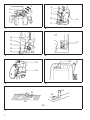
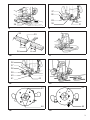
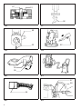
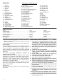
GB F D I NL E P DK S N SF GR Router Electronic Router Instruction Manual Défonceuse Défonceuse électronique Manuel d’instructions Oberfräse Elektronische Oberfräse Betriebsanleitung Fresa Fresa elettronica Istruzioni per l’uso Bovenfrees Elektronische bovenfrees Gebruiksaanwijzing Máquina para fresar Máquina para fresar electrónica Manual de instrucciones Fresadora Fresadora electrónica Manual de instruço˜es Overfræser Elektronisk overfræser Brugsanvisning Handöverfräs Elektronisk handöverfräs Bruksanvisning Overfres Elektronisk overfres Bruksanvisning Yläjyrsin Elektroninen yläjyrsin Käyttöohje ¶ÂÚÈÛÙÚ¡fiÌÂÓË ˇÚ·›˙· ∏ÏÂÎÙÚÔÓÈ΋ ÂÚÈÛÙÚ¡fiÌÂÓË ˇÚ·›˙· √‰ËÁ›Â˜ ¯Ú‹Ûˆ˜ 3612 3612C 1 4 6 7 8 2 5 3 10 9 11 1 2 12 13 17 14 15 16 3 4 20 18 19 5 6 22 23 21 23 22 24 25 7 2 27 28 29 30 26 8 31 9 32 33 55 mm 34 35 55 mm 10 11 36 37 38 39 40 41 42 12 14 13 43 45 44 46 15 3 47 51 48 49 50 52 16 17 52 52 53 18 19 54 55 20 21 57 58 56 22 4 23 Symbols The following show the symbols used for the machine. Be sure that you understand their meaning before use. Symboles Nous donnons ci-dessous les symboles utilisés pour l’outil. Assurez-vous que vous en avez bien compris la signification avant d’utiliser l’outil. Symbole Die folgenden Symbole werden für die Maschine verwendet. Machen Sie sich vor der Benutzung unbedingt mit ihrer Bedeutung vertraut. Symboli Per questo utensile vengono usati i simboli seguenti. Bisogna capire il loro significato prima di usare l’utensile. Symbolen Voor dit gereedschap worden de volgende symbolen gebruikt. Zorg ervoor dat u de betekenis van deze symbolen begrijpt alvorens het gereedschap te gebruiken. Símbolos A continuación se muestran los símbolos utilizados con esta herramienta. Asegúrese de que entiende su significado antes de usarla. Símbolos O seguinte mostra os símbolos utilizados para a ferramenta. Certifique-se de que compreende o seu significado antes da utilização. Symboler Nedenstående symboler er anvendt i forbindelse med denne maskine. Vær sikker på, at De har forstået symbolernes betydning, før maskinen anvendes. Symboler Det följande visar de symboler som används för den här maskinen. Se noga till att du förstår deras innebörd innan maskinen används. Symbolene Følgende viser de symblene som brukes for maskinen. Det er viktig å forstå betydningen av disse før maskinen tas i bruk. Symbolit Alla on esitetty koneessa käytetyt symbolit. Opettele näiden merkitys, ennen kuin käytät konetta. ™‡Ì‚ÔÏ· ∆· ·ÎfiÏÔ˘ı· ‰Â›¯ÓÔ˘Ó Ù· ۇ̂ÔÏ· Ô˘ ¯ÚËÛÈÌÔÔÈÔ‡ÓÙ·È ÁÈ· ÙÔ Ì˯¿ÓËÌ·. µÂ‚·Èˆı›Ù fiÙÈ Î·Ù·Ï·‚·›ÓÂÙ ÙË ÛËÌ·Û›· ÙÔ˘˜ ÚÈÓ ·fi ÙË ¯Ú‹ÛË. [ Read instruction manual. [ Lire le mode d’emploi. [ Bitte Bedienungsanleitung lesen. [ Leggete il manuale di istruzioni. [ Lees de gebruiksaanwijzing. [ Lea el manual de instrucciones. [ Leia o manual de instruço˜es. [ Læs brugsanvisningen. [ Läs bruksanvisningen. [ Les bruksanvisingen. [ Katso käyttöohjeita. [ ¢È·‚¿ÛÙ ÙȘ Ô‰ËÁ›Â˜ ¯Ú‹Û˘. [ DOUBLE INSULATION [ DOUBLE ISOLATION [ DOPPELT SCHUTZISOLIERT [ DOPPIO ISOLAMENTO [ DUBBELE ISOLATIE [ DOBLE AISLAMIENTO [ DUPLO ISOLAMENTO [ DOBBELT ISOLERET [ DUBBEL ISOLERING [ DOBBEL ISOLERING [ KAKSINKERTAINEN ERISTYS [ ¢π¶§∏ ª√¡ø™∏ 5 ENGLISH 1 2 3 4 5 6 7 8 9 10 11 12 13 14 15 16 17 18 19 20 Wrench Router bit Shaft lock Tighten Loosen Nylon nut Stopper pole Fast-feed button Lock lever Adjusting hex bolt Stopper Stopper pole Chip deflector Adjusting hex bolt Hex nut Stopper Switch lever Lock-off button Switch trigger Speed change knob Explanation of general view 21 22 23 24 25 26 27 28 29 30 31 32 33 34 35 36 37 38 39 Workpiece Bit revolving direction Feed direction View from the top of the tool Correct bit feed direction Straight guide Guide holder Fine adjusting screw Wing bolt (B) Wing bolt (A) Stright guide More than 15 mm Straight guide Wood Trimmer guide Wing bolt (A) Guide roller Guide holder Fine adjusting screw 40 41 42 43 44 45 46 47 48 49 50 51 52 53 54 55 56 57 58 Wing bolt (B) Wing bolt (C) Trimmer guide Templet guide Screw Templet guide Lock plate lever Bit Base Templet Workpiece Templet guide Vaccum head Screws Support Lock lever Limit mark Brush holder cap Screwdriver SPECIFICATIONS Model 3612 Collet capacity .................................................................. 12 mm or 1/2″ Plunge capacity ................................................................ 0 – 60 mm No load speed (min–1) ..................................................... 22,000 Overall heigth .................................................................... 297 mm Base diameter ................................................................... 160 mm Net weight ........................................................................ 5.8 kg • Due to the continuing program of research and development, the specifications herein are subject to change without prior notice. • Note: Specifications may differ from country to country. Power supply The tool should be connected only to a power supply of the same voltage as indicated on the nameplate, and can only be operated on single-phase AC supply. They are double-insulated in accordance with European Standard and can, therefore, also be used from sockets without earth wire. For public low-voltage distribution systems of between 220 V and 250 V Switching operations of electric apparatus cause voltage fluctuations. The operation of this device under unfavorable mains conditions can have adverse effects to the operation of other equipment. With a mains impedance equal or less than 0.32 Ohms it can be presumed that there will be no negative effects. The mains socket used for this device must be protected with a fuse or protective circuit breaker having slow tripping characteristics. Safety hints For your own safety, please refer to enclosed safety instructions. 6 3612C 12 mm or 1/2″ 0 – 60 mm 9,000 – 23,000 297 mm 160 mm 6.0 kg ADDITIONAL SAFETY RULES ENB033-2 1. Hold tool by insulated gripping surfaces when performing an operation where the cutting tool may contact hidden wiring or its own cord. Contact with a ‘‘live’’ wire will make exposed metal parts of the tool ‘‘live’’ and shock the operator. 2. Wear hearing protection during extended period of operation. 3. Handle the bits very carefully. 4. Check the bit carefully for cracks or damage before operation. Replace cracked or damaged bit immediately. 5. Avoid cutting nails. Inspect for and remove all nails from the workpiece before operation. 6. Hold the tool firmly with both hands. 7. Keep hands away from rotating parts. 8. Make sure the bit is not contacting the workpiece before the switch is turned on. 9. Before using the tool on an actual workpiece, let it run for a while. Watch for vibration or wobbling that could indicate improperly installed bit. 10. Be careful of the bit rotating direction and the feed direction. 11. Do not leave the tool running. Operate the tool only when hand-held. 12. Always switch off and wait for the bit to come to a complete stop before removing the tool from workpiece. 13. Do not touch the bit immediately after operation; it may be extremely hot and could burn your skin. 14. Always lead the power supply cord away from the tool towards the rear. 15. Do not smear the tool base carelessly with thinner, gasoline, oil or the like. They may cause cracks in the tool base. 16. Draw attention to the need to use cutters of the correct shank diameter and which are suitable for the speed of the tool. SAVE THESE INSTRUCTIONS. OPERATING INSTRUCTIONS Installing or removing the router bit (Fig. 1) Important: Always be sure that the tool is switched off and unplugged from the supply outlet before installing or removing the router bit. Insert the router bit all the way into the collet. Press the shaft lock to keep the shaft stationary and use the wrench to tighten the collet nut securely. When using router bits with smaller shank diameter, first mount the appropriate collet, then install the bit as described above. CAUTION: • Do not tighten the collet without inserting a router bit. • Use always a collet which is suitable for the shank diameter of the router bit. • Use only router bits of which the maximum speed, as indicated on the bit, does exceed the maximum speed of the router. Switching ON and OFF For tool without lock-off button (Fig. 4) CAUTION: Make sure that the shaft lock is released before the switch is turned on. To switch on, move the switch lever to the ‘‘ON’’ position. To switch off, move the switch lever to the ‘‘OFF’’ position. For tool with lock-off button (Fig. 5) CAUTION: • Before plugging in the tool, always check to see that the switch trigger actuates properly and returns to the ‘‘OFF’’ position when released. • Make sure that the shaft lock is released before the switch is turned on. To switch on, push the lock-off button and at the same time press the trigger. To switch off, release the trigger. Speed change knob (Fig. 6) For 3612C only The tool speed can be infinitely adjusted between 9,000 rpm and 23,000 rpm by turning the speed change knob. This allows the ideal speed to be selected for optimum material processing, i.e. the speed can be correctly adjusted to suit the material and bit diameter. Refer to the table below for relationship between the number settings on the speed change knob and approx. tool speed. Adjusting the depth of cut (Fig. 2) Important: Always be sure that the tool is switched off and unplugged before adjusting the depth of cut. Place the tool on a flat surface. Loosen the lock lever and lower the tool body until the bit just touches the flat surface. Press the lock lever down to lock the tool body. While pressing the fast-feed button, move the stopper pole up or down until the desired depth of cut is obtained. Minute depth adjustments can be obtained by turning the stopper pole (1.5 mm per turn). CAUTION: The depth of cut should not be more than 20 mm at a pass when cutting grooves. For extra-deep grooving operations, make two or three passes with progressively deeper bit settings. Nylon nut (Fig. 2) Number RPM 1 9,000 2 12,000 3 15,000 4 19,000 5 23,000 Operation (Fig. 7) Place the tool on the workpiece and switch on. Release the lock lever and slowly lower the tool onto the workpiece until preset routing depth is reached. Move the tool forward using both hands. When cutting edges, the workpiece surface should be on the left side of the bit in the feed direction as shown in Fig. 7. The upper limit of the tool body can be adjusted by turning the nylon nut. Do not lower the nylon nut too low. The bit will protrude dangerously. Stopper (Fig. 3) As the rotary stopper has three adjusting hex bolts, you can easily obtain three different depths of cut without readjusting the stopper pole. To adjust the hex bolts, loosen the hex nuts on them and turn the hex bolts. After obtaining the desired position, tighten the hex nuts to secure the hex bolts. 7 Straight guide Dust extraction When using the straight guide, be sure to install it on the right side in the feed direction. (Fig. 8) Install the straight guide on the guide holder with the wing bolt (B). Insert the guide holder into the holes in the tool base and tighten the wing bolt (A). To adjust the distance between the bit and the straight guide, loosen the wing bolt (B) and turn the fine adjusting screw (1.5 mm per turn). (Fig. 9) Wider straight guide of desired dimensions may be using the convenient holes in the guide to bolt on extra pieces of wood. When using a large diameter bit, attach pieces of wood to the straight guide which have a thickness of more than 15 mm to prevent the bit from striking the straight guide. (Fig. 10) For tool without lock plate Use the vacuum head for dust extraction. Install the vacuum head on the tool base using the two screws. (Fig. 17 & 18) Then connect a vacuum cleaner to the vacuum head. (Fig. 21) Trimmer guide When using the trimmer guide, be sure to install it on the right side in the feed direction. (Fig. 11) Install the trimmer guide on the guide holder with the wing bolt (B). Insert the guide holder into the holes in the tool base and tighten the wing bolt (A). To adjust the distance between the bit and the trimmer guide, loosen the wing bolt (B) and turn the fine adjusting screw (1.5 mm per turn). When adjusting the guide roller up or down, loosen the wing bolt (C). (Fig. 12) For tool with lock plate Use the vacuum head for dust extraction. To install the vacuum head, raise the lock lever on it. Place the vacuum head on the tool base so that its top will be caught in the hook on the tool base. Insert the supports on the vacuum head into the hooks on the front of the tool base. Push down the lock lever onto the tool base. (Fig. 19 & 20) Then connect a vacuum cleaner to the vacuum head. (Fig. 21) To remove the vacuum head, raise the lock lever. Pull the vacuum head out of the tool base while holding the supports between thumb and finger. MAINTENANCE CAUTION: Always be sure that the tool is switched off and unplugged before carrying out any work on the tool. Templet guide Replacement of carbon brushes (Fig. 22 & 23) For tool without lock plate The templet guide provides a sleeve through which the bit passes, allowing use of the router with templet patterns. (Fig. 13) To install the templet guide, loosen the screws on the tool base, insert the templet guide and then tighten the screws. (Fig. 14) Secure the templet to the workpiece. Place the tool on the templet and move the tool with the templet guide sliding along the side of the templet. (Fig. 16) Replace carbon brushes when they are worn down to the limit mark. Both identical carbon brushes should be replaced at the same time. For tool with lock plate The templet guide provides a sleeve through which the bit passes, allowing use of the router with templet patterns. (Fig. 13) To install the templet guide, pull the lock plate lever and insert the templet guide. (Fig. 15) Secure the templet to the workpiece. Place the tool on the templet and move the tool with the templet guide sliding along the side of the templet. (Fig. 16) 8 To maintain product safety and reliability, repairs, maintenance or adjustment should be carried out by Makita Authorized Service Center. NEDERLANDS 1 2 3 4 5 6 7 8 9 10 11 12 13 14 15 16 17 18 19 20 Sleutel Freesbit Asvergrendeling Vastzetten Loszetten Nylonmoer Aanslagnok Sneltoevoerknop Grendel Zeskantstelbout Aanslag Aanslagnok Spaandeflector Zeskantstelbout Zeskantmoer Aanslag Schakelhendel Ontgrendelingsknop Trekkerschakelaar Toerentalregelaar Verklaring van algemene gegevens 21 22 23 24 25 26 27 28 29 30 31 32 33 34 35 36 37 38 39 Werkstuk Bitdraairichting Toevoerrichting Gezien vanaf de bovenkant van het gereedschap Juiste bittoevoerrichting Rechte geleider Geleiderhouder Fijnstelschroef Vleugelbout (B) Vleugelbout (A) Rechte geleider Meer dan 15 mm Rechte geleider Hout Trimgeleider Vleugelbout (A) Geleiderol Geleiderhouder Fijnstelschroef 40 41 42 43 44 45 46 47 48 49 50 51 52 53 54 55 56 57 58 Vleugelbout (B) Vleugelbout (C) Trimgeleider Malgeleider Schroef Malgeleider Borgplaathendel Bit Voet Mal Werkstuk Malgeleider Vacuümkop Schroeven Steun Grendel Limietmarkering Borstelhouderkap Schroevendraaier TECHNISCHE GEGEVENS Model 3612 Spantangcapaciteit ........................................................... 12 mm Plunjercapaciteit ................................................................ 0 – 60 mm Toerental onbelast (min–1) ................................................ 22 000 Totale hoogte .................................................................... 297 mm Voetdiameter ..................................................................... 160 mm Netto gewicht .................................................................... 5,8 kg • In verband met ononderbroken research en ontwikkeling behouden wij ons het recht voor bovenstaande technische gegevens te wijzigen zonder voorafgaande kennisgeving. • Opmerking: De technische gegevens kunnen van land tot land verschillen. Stroomvoorziening Het gereedschap mag alleen worden aangesloten op een stroombron van hetzelfde voltage als aangegeven op de naamplaat, en kan alleen op enkel-fase wisselstroom worden gebruikt. Het gereedschap is dubbelgeı¨soleerd volgens de Europese standaard en kan derhalve ook op een niet-geaard stopcontact worden aangesloten. Voor openbare laagspanningsverdeelsystemen van tussen 220 V en 250 V Schakelbedieningen van elektrische toestellen veroorzaken spanningsschommelingen. De bediening van dit gereedschap onder ongunstige lichtnetomstandigheden kan een nadelige invloed hebben op de bediening van andere apparatuur. Het kan worden aangenomen dat er geen negatieve effecten zullen zijn wanneer de netimpedantie gelijk is aan of minder is dan 0,32 Ohm. Het stopcontact dat voor dit gereedschap wordt gebruikt, moet beveiligd zijn door een zekering of een stroomonderbreker met trage afschakelkarakteristieken. Veiligheidswenken Voor uw veiligheid dient u de bijgevoegde Veiligheidsvoorschriften nauwkeurig op te volgen. 18 3612C 12 mm 0 – 60 mm 9 000 – 23 000 297 mm 160 mm 6,0 kg AANVULLENDE VEILIGHEIDSVOORSCHRIFTEN 1. Houd het gereedschap vast bij de geïsoleerde greepoppervlakken wanneer u werkt op plaatsen waar de frees met verborgen elektrische bedrading of zijn eigen netsnoer in aanraking kan komen. Door contact met een onder spanning staande draad zullen ook de niet-geïsoleerde metalen delen van het gereedschap onder spanning komen te staan, zodat de gebruiker een elektrische schok kan krijgen. 2. Gebruik een oorbescherming, wanneer U lange tijd met dit gereedschap denkt te werken. 3. Behandel de frezen zeer voorzichtig. 4. Kontroleer alvorens het gereedschap te gebruiken de frees op beschadigingen en barsten. Een beschadigde of gebarsten frees dient onmiddellijk te worden vervangen. 5. Zorg ervoor dat tijdens het frezen de frees niet in aanraking komt met spijkers. Verwijder zo mogelijk alle spijkers van het werkstuk. 6. Houd het gereedschap met beide handen stevig vast. 7. Houd uw handen uit de buurt van de roterende delen. 8. Zorg ervoor dat de frees niet in aanraking is met het werkstuk, wanneer u het gereedschap inschakelt. 9. Alvorens het werkstuk te frezen, dient u het gereedschap een tijdje te laten draaien om te kontroleren of er trillingen of schommelingen zijn die op een verkeerd ingezette frees kunnen wijzen. 10. Let op de draairichting van de frees en de freesrichting, of deze met elkaar overeenkomen. 11. Schakel altijd het gereedschap uit wanneer u tijdens het frezen weg moet. Schakel het gereedschap alleen in wanneer u het vast houdt. 12. Schakel altijd uit en wacht tot de frees helemaal tot stilstand is gekomen, alvorens het gereedschap van het werkstuk te verwijderen. 13. Raak de frees onmiddellijk na het gebruik niet aan. De frees is dan nog ontzettend heet en kan dus brandwonden veroorzaken. 14. Zorg dat het netsnoer tijdens het werk altijd achter het gereedschap geplaatst is. 15. Wees voorzichtig en veeg het voetstuk van het gereedschap niet af met verfverdunner, benzine, olie of iets dergelijks, aangezien er anders barsten in kunnen komen. 16. Zorg ervoor dat u uitsluitend frezen gebruikt die de juiste schachtdiameter hebben en geschikt zijn voor de snelheid van het gereedschap. Nylonmoer (Fig. 2) BEWAAR DEZE VOORSCHRIFTEN. Om in te schakelen, schuift u de schakelhendel naar de ‘‘ON’’ stand. Om uit te schakelen, schuift u de schakelhendel naar de ‘‘OFF’’ stand. BEDIENINGSVOORSCHRIFTEN Aanbrengen of verwijderen van de freesbit (Fig. 1) Belangrijk: Controleer altijd of het gereedschap is uitgeschakeld en zijn stekker uit het stopcontact is verwijderd alvorens de freesbit aan te brengen of te verwijderen. Steek de freesbit volledig in de spantang. Druk de asvergrendeling in om de as te vergrendelen en draai de moer van de spantang met de sleutel stevig vast. Monteer bij gebruik van freesbits met een kleinere schachtdiameter eerst een daarvoor geschikte spantang en installeer vervolgens de freesbit zoals hierboven beschreven. LET OP: • Zet de spantang niet vast zonder dat een freesbit in de spantang is aangebracht. • Gebruik altijd een spantang die geschikt is voor de schachtdiameter van de freesbit. • Gebruik uitsluitend freesbits met een maximale draaisnelheid (aangegeven op de bit) die de maximale snelheid van de frees niet overschrijdt. Regelen van de snijdiepte (Fig. 2) Belangrijk: Controleer altijd of het gereedschap is uitgeschakeld en zijn stekker uit het stopcontact is verwijderd alvorens de snijdiepte te regelen. Plaats het gereedschap op een effen oppervlak. Zet de grendel los en laat het gereedschap zakken tot de bit het oppervlak raakt. Druk de grendel omlaag om het gereedschap vast te zetten. Druk op de sneltoevoerknop en beweeg de aanslagnok op en neer tot de gewenste snijdiepte is verkregen. Fijnregeling is mogelijk door de aanslagnok te draaien (1,5 mm per slag). De bovenlimiet van het gereedschap kan worden geregeld door de nylonmoer te draaien. Laat de nylonmoer niet te laag zakken, aangezien de bit dan gevaarlijk zal uitsteken. Aanslag (Fig. 3) De draai-aanslag heeft drie zeskantstelbouten, zodat u makkelijk drie verschillende snijdieptes kunt bekomen zonder de instelling van de aanslagnok te wijzigen. Om de zeskantstelbouten in te stellen, draait u de zeskantmoeren los en draait u aan de zeskantbouten. Wanneer de gewenste positie is bereikt, draait u de zeskantmoeren vast om de zeskantbouten te blokkeren. In- en uitschakelen Gereedschap zonder ontgrendelingsknop (Fig. 4) LET OP: Controleer of de asvergrendeling in de vrije stand staat alvorens de schakelaar in te schakelen. Gereedschap met ontgrendelingsknop (Fig. 5) LET OP: • Alvorens de stekker in het stopcontact te steken, moet u altijd eerst controleren of de trekkerschakelaar goed functioneert en bij loslaten naar de ‘‘OFF’’ positie terugkeert. • Controleer of de asvergrendeling in de vrije stand staat alvorens de schakelaar in te schakelen. Om in te schakelen, drukt u de ontgrendelingsknop en de trekkerschakelaar tegelijkertijd in. Om uit te schakelen, laat u de trekkerschakelaar los. Toerentalregelaar (Fig. 6) Alleen voor 3612C Het toerental kan traploos worden ingesteld van 9 000 tot 23 000 tpm door de toerentalregelaar te draaien. Zo kan het ideale toerental voor het te bewerken materiaal worden geselecteerd, m.a.w. het toerental kan perfect worden afgestemd op het materiaal en de bitdiameter. De tabel hieronder geeft een overzicht van de cijfers op de snelheidsregelaar en het toerental waarmee deze ongeveer overeenstemmen. Cijfer tpm 1 9 000 2 12 000 3 15 000 4 19 000 5 23 000 LET OP: De snijdiepte mag bij het maken van groeven niet meer dan 20 mm per beurt bedragen. Diepere groeven moeten in twee of drie beurten worden gemaakt door de bit telkens dieper in te stellen. 19 Werking (Fig. 7) Stofafzuiging Plaats het gereedschap op het werkstuk en schakel het in. Zet de grendel in de vrije stand en laat het gereedschap langzaam op het werkstuk zakken tot de vooringestelde freesdiepte is bereikt. Duw het gereedshap met beide handen vooruit. Bij het snijden van randen moet het werkstukoppervlak links van de bit zitten in de toevoerrichting zoals afgebeeld in Fig. 7. Voor gereedschap zonder borgplaat Gebruik de zuigkop voor stofafzuiging. Monteer de zuigkop op de gereedschapsvoet met behulp van de twee schroeven. (Fig. 17 en 18) Sluit vervolgens een stofzuiger aan op de zuigkop. (Fig. 21) Rechte geleider Bij gebruik van de rechte geleider moet u deze aan de rechterzijde in de toevoerrichting installeren. (Fig. 8) Monteer de rechte geleider met behulp van de vleugelbout (B) op de geleiderhouder. Steek de geleiderhouder in de gaten in de gereedschapsvoet en draai de vleugelbout (A) vast. Om de afstand tussen de bit en de rechte geleider te regelen, draait u de vleugelbout (B) los en verdraait u de fijnstelschroef (1,5 mm per slag). (Fig. 9) De rechte geleider kan worden verbreed door extra stukken hout met bouten aan de geleider te bevestigen door de gaten in de geleider. Bij gebruik van een bit met grote diameter, bevestigt u stukken hout met een dikte van meer dan 15 mm aan de rechte geleider, om te voorkomen dat de bit de rechte geleider raakt. (Fig. 10) Trimgeleider Bij gebruik van de trimgeleider moet u deze aan de rechterzijde in de toevoerrichting installeren. (Fig. 11) Monteer de trimgeleider met behulp van de vleugelbout (B) op de geleiderhouder. Steek de geleiderhouder in de gaten in de gereedschapsvoet en draai de vleugelbout (A) vast. Om de afstand tussen de bit en de trimgeleider te regelen, draait u de vleugelbout (B) los en verdraait u de fijnstelschroef (1,5 mm per slag). Draai de vleugelmoer (C) los om de geleiderol op of neer te bewegen. (Fig. 12) Malgeleider Voor gereedschap zonder borgplaat De malgeleider heeft een gleuf voor de bit, zodat de routerfrees met sjablonen kan werken. (Fig. 13) Om de malgeleider te monteren, draait u eerst de schroeven op de gereedschapsvoet los. Steek dan de malgeleider erin en draai de schroeven vast. (Fig. 14) Zet de mal vast op het werkstuk. Plaats het gereedschap op de mal en beweeg het gereedschap met de malgeleider langs de mal. (Fig. 16) Voor gereedschap met borgplaat De malgeleider heeft een gleuf voor de bit, zodat de routerfrees met sjablonen kan werken. (Fig. 13) Om de malgeleider te monteren, trekt u aan de borgplaathendel en steekt u de malgeleider erin. (Fig. 15) Zet de mal vast op het werkstuk. Plaats het gereedschap op de mal en beweeg het gereedschap met de malgeleider langs de mal. (Fig. 16) 20 Voor gereedschap met borgplaat Gebruik de zuigkop voor stofafzuiging. Om de zuigkop te installeren, heft u de grendel erop omhoog. Paats de zuigkop op de gereedschapsvoet zodat zijn bovenkant in de haak op de gereedschapsvoet past. Steek de steunen op de zuigkop in de haken vooraan op de gereedschapsvoet. Duw de grendel omlaag op de gereedschapsvoet. (Fig. 19 en 20) Sluit vervolgens een stofzuiger aan op de zuigkop. (Fig. 21) Om de zuigkop te verwijderen, brengt u de grendel omhoog. Trek de zuigkop uit de gereedschapsvoet door de steunen tussen duim en wijsvinger te houden. ONDERHOUD LET OP: Zorg er altijd voor dat het gereedschap is uitgeschakeld en de stekker uit het stopcontact is verwijderd alvorens onderhoud aan het gereedschap uit te voeren. Vervangen van koolborstels (Fig. 22 en 23) Vervang de borstels wanneer ze tot aan de aangegeven limiet zijn afgesleten. Beide koolborstels dienen tegelijkertijd te worden vervangen. Opdat het gereedschap veilig en betrouwbaar blijft, dienen alle reparaties, onderhoud of afstellingen te worden uitgevoerd bij een erkend Makita service centrum.