1
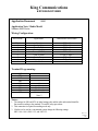
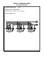
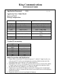
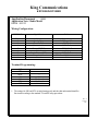
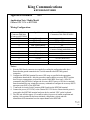
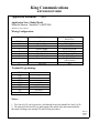
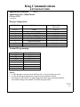
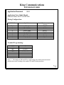
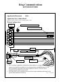
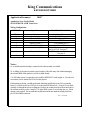
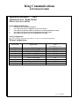
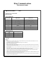
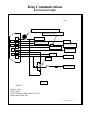
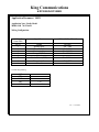
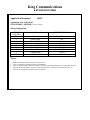
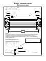
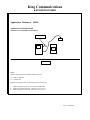
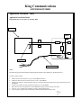
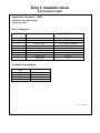
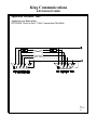
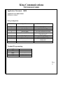
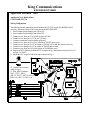
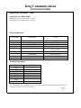
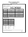
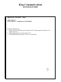
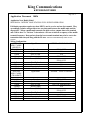
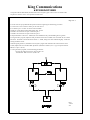
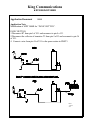
King Communications
KDT5000/KDT5000R
Applications Document Index
10001
10002
10003
10004
10005
10006
10007
10008
10009
10010
10011
10012
10013
10014
10015
10016
10017
10018
10019
10020
10021
10022
10023
10024
10025
10026
10027
10028
10029
10030
10031
10032
10033
10034
10035
10036
10037
10038
Panic Switch
Motorola Maxtrac Series “HLN9123A Logic Bd. and 688010W76-A”
Johnson 8600 Series
Standard GX1510U
“Back to Back” Cable Construction
Kenwood TK840
Bendix/King EPH Portable
Motorola Radius GM300
RELM - SLU25
Kenwood TK760
Garmin GPS 35/36 to KDT5000
Motorola Maxtrac “SmartNet” “HLN9313A Logic Board”
Motorola GTX and LCS 2000” Model # M11UGD6CB1AN and M10UGD6DC5AN
Ericsson MDX “LBI-38848E”
Motorola Radius M1225
KDT5000 to Radio Interface Cable Construction (KRIC Cable)
SEA ESP504/520 ACSB Transceiver
Motorola Maxar 80
Maxon SM-2450
MIDLAND 70-1337 Bantam Mobile
MIDLAND 70-1336A/B
SEA ESP520DX / ESP520D
KRIC Power Circuit Protection Adaptor
Modication of the KDT5000 for Data Detect
Flag Fall Interface for Taxi Meter
UNIDEN SMU 250KTS
“Back to Back” cable modified
JOHNSON VIKING
KENWOOD TK805
KENWOOD TK810
MAXON SM-4450
STANDARD GX1710
MIDLAND 70-1341/1344/1441/1444&70-1391/1394/1491/1494 TITAN
MOTOROLA SM 50 “RADIUS”
“DATA DETECT” MODIFCATION FOR KDT5000R
MOTOROLA MITREK BASE full duplex modification
MOTOROLA MSF 5000 BASE full duplex modification
Kenwood TK880
King Communications
KDT5000/KDT5000R
Aplication Document
10001
Application Note / Radio Model
“Panic Switch” Installation
Notes:
1. The parameter structure for the command PEN is “PEN 1”.
2. Install a10k ohm 1/8 watt resistor between pin 1 and pin 9 of the DB9M connector of the
radio interface cable.
3. An industrial grade N.O. push button switch is recommended for the “panic switch”.
4. A wire must also be attached between pin 9 of the DB9M connector and one pole of the N.O.
contact of the panic switch. See diagram below.
5. Connect the other pole of the N.O. contact to a wire going to pin 5 of the DB9M connector.
6. The panic function is initiated when pin 9 is pulled high momentarily.
7. Verify that all MDT’s have been modified per App. Notes 10039 or 10040.
Wiring Configuration:
Rev.2.4
7 / 24 / 99
WF
King Communications
KDT5000/KDT5000R
Application Document 10002
Application Note / Radio Model
Motorola Maxtrac Series
“HLN9123A Logic Bd. and 688010W76-A”
Wiring Configuration:
KDT5000R
Signal Name
PIN #1
2
3
4
5
6
7
8
Ground
Speaker Mute (MUP)
Press To Talk (PTP)
Receive Audio
Power (12VDC)
Clear To Send (TRP)
Trunk Decode (SQP)
Transmit Audio
9
Not Used
Maxtrac logic board
688010w76-A
Any ground area
Base of Q509
Pin #11 of J8 Conn.
Pin #1 of U552B
Pin #5 of J8 Conn.
Collector Q652
Collector Q552
Pin #2 of U652A
(15K in series)
NA
Terminal Programming:
SQP
PTP
MUP
LKI
RKI
SRL
STL
TRP
SRT
+
1 80
1 10
23: Note 1
18: Note 1
7 500 0 0 0 0 0
Notes:
1. The settings for SRL and STL are initial settings only and the radio and terminal should be
fine-tuned according to the standard TX and RX setup procedures.
Rev.2.3
3/30/99
WF
King Communications
KDT5000/KDT5000R
Application Document
10003
Application Note / Radio Model
Johnson 8600 Series
Wiring Configuration:
KDT5000R
Signal Name
Johnson 8600 Series Radio
PIN #1
2
3
4
5
6
7
8
9
Ground
Speaker Mute
Press To Talk
Receive Audio
Power (12VDC)
Clear To Send
Carrier Detect
Transmit Audio
Not Used
P2 Pin #9
P2 Pin #6
P2 Pin #2
P2 Pin #4
P2 Pin #5
P2 Pin #1 Note 2
P2 Pin # 7
P2 Pin #11
NA
Terminal Programming:
SQP
PTP
MUP
TRP
RKI
LKI
STL
SRL
SRT
+
+
10
80
26: Note 1
25: Note 1
7 500 0 0 0 0 0
Note: 3
Notes:
1. The settings for SRL and STL are initial settings only and the radio and terminal should be
fine-tuned according to the standard TX and RX setup procedures.
2. This connection is required for trunking mode only.
3. If radio is to be used in a conventional system change the following settings:
SRT 0 0 0 0 0 0 0, RKI 1 25, and LKI 1 25.
Rev.2.3
3/30/99
WF
King Communications
KDT5000/KDT5000R
Application Document
10004
Application Note / Radio Model
Standard GX1510U
Wiring Configuration:
KDT5000R
Signal Name
Radio
PIN #1
2
3
4
5
6
7
8
Ground
Speaker Mute
Press To Talk
Receive Audio
Power (12VDC)
Unused
Carrier Detect (COR)
Transmit Audio
9
Unused
Any Ground Connection
Gate of Q606
Pin #3 of Mic Jack
Junction R128 and C152
Collector of Q403
NA
Collector of Q712
Junction of R280 and VR202 with
15K resistor in series
NA
Terminal Programming:
SQP
PTP
MUP
LKI
SRT
+
20
0000000
Rev.2.3
3/30/99
WF
King Communications
KDT5000/KDT5000R
Application Document
10005
Application Note / Radio Model
KDT5000R “Back to Back” Cable Construction
Wiring Configuration:
12VDC
+
DB9 Male
Solder side
4K7
4K7
DB9 Male
Solder side
DB9 Male
Solder side
-
King Communications
KDT5000/KDT5000R
Application Document
10006
Pg. 1 of 2
Application Note / Radio Model
Kenwood TK840
Wiring Configuration:
KDT5000R
Signal Name
KCT19 Accessory Connection Cable
PIN #1 (Brn.)
2 (Blu.)
3 (Red)
4 (Orng.)
5 (Yel.)
6 (Grn.)
Ground
Speaker Mute
Press To Talk
Receive Audio
Power (12VDC)
Clear to Send
7 (Violet)
Carrier Detect (COR)
8 (Gray)
9 (Wht.)
Transmit Audio
Unused
Pin A-6 (Red)
Pin A-12 (See mods #1) (Yel.-C1)
Pin A-8 (Purple)
Pin A-4 (See mods #3) (Brwn.)
Pin A-7 (Orng.-Large)
Pin A-13 (See mods #4 and notes #1)
(White)
Pin A-11 (See mods #2 and notes #2)
(Gray)
Pin A-9 (Yel.)
NA
Terminal Programming:
SQP
PTP
MUP
SPS
SRT
TRP
RKI
LKI
+
100
7 500 0 0 0 0 0
1 20
1 80
Radio Preparation and Modification:
1. Clip the yellow wire on the KCT19 from its connector C1. Add the 4” length of yellow wire
to the just cut KCT19 yellow wire and insulate the connection. Solder the other end of the
newly added yellow wire to the base of Q19 (grid location G11)
2. TRUNKING USE ONLY. Clip the gray wire on the KCT19 from its connector D8. Add the
4” length of gray wire to the just cut KCT19 gray wire and insulate the connection. Solder
the other end of the newly added gray wire to the base of Q20.
3. Clip the brown wire on the KCT19 from its connector D1, ensuring to leave enough length
on both ends to solder to. Add the 2K ohm resistor in series with the brown wire and properly
insulate the connectors.
4. Program the radio for an Access Logic Signal of Continuous
King Communications
KDT5000/KDT5000R
Pg. 2 of 2
Notes:
1. Leave this connection un-terminated if radio is to be used in a conventional only system.
2. Do not perform modification step #2 if radio is to be used in a conventional only system.
3. If radio is to be used in a conventional only system, replace the above listed KDT settings
with the following: SRT 0 0 0 0 0 0 0, RKI 1 25, and LKI 1 25.
4. Align the KDT per the alignment instructions in the KDT training manual. Adjustment of the
radio’s TX deviation may be required.
Rev. 3
4/28/99
WF
King Communications
KDT5000/KDT5000R
Application Document
10007
Application Note / Radio Model
Bendix/King EPH Portable
Wiring Configuration:
KDT5000R
Signal Name
Side Connector via LAA0602
PIN #1
2
3
4
Ground
Unused
Press To Talk
Receive Audio
5
6
7
8
9
Power (12VDC)
Unused
Carrier Detect (COR)
Transmit Audio
Unused
#3 of J17
NA
#2 of J17
Center pin of J15
Audio Jack
#1 of J17
NA
#5 of J17
#4 of J17
NA
Terminal Programming:
SQP
PTP
LKI
SRT
+
100
00000000
Notes:
Requires use of an LAA0602 Accessories connector from B/K radio. The following mod will
convert PRI switch to a MDT mode or Programming mode switch:
1. Remove R55 (Options board)
2. Cut pin 3 of P11 Control board.
3. Cut path on both sides of SW2.
4. Add jumper between top leg of SW2 and pad of R55 (Junction R55 and C56)
5. Add jumper between center leg of SW2 and pad of R55 (Junction R55 and J10 pin 6)
6. Add jumper between bottom leg of SW2 and I4/Options board pin 5
7. Add jumper between top leg of SW3 and Gnd.
Rev.3
3/30/99
WF
King Communications
KDT5000/KDT5000R
Application Document
10008
Application Note / Radio Model
Motorola Radius GM300
Wiring Configuration:
KDT5000R
Signal Name
Rear Accessory Connector Pin #
PIN #1
2
3
4
5
6
7
8
9
Ground
Speaker Mute
Press To Talk
Receive Audio
Power (12VDC)
Unused
Carrier Detect (COR)
Transmit Audio
Unused
7
6
3
11
13
NA
4
5
NA
Terminal Programming:
SQP
PTP
LKI
SRT
+
100
0000000
Rev. 2
3/30/99
WF
King Communications
KDT5000/KDT5000R
Application Document
10009
Application Note / Radio Model
RELM - SLU25
Wiring Configuration:
KDT5000R
Signal Name
Radio
PIN #1
2
3
4
5
6
7
8
9
Ground
Speaker Mute
Press To Talk
Receive Audio
Power (12VDC)
Unused
Carrier Detect (COR)
Transmit Audio
Unused
Any Ground Connection
U201 pin #13
J301 Pin 1
U301 Pin 9
SW101 Pin 5
NA
U204 Pin 7
P201 Pin 4 100K ohm in series
NA
Terminal Programming:
SQP
PTP
MUP
LKI
SRL
STL
SRT
+
+
20
23: Note 1
18: Note 1
0000000
1. The settings for SRL and STL are initial settings only and the radio and terminal should be
fine-tuned according to the standard TX and RX setup procedures.
Rev. 4
3/30/99
WF
King Communications
KDT5000/KDT5000R
Application Document
10010
Application Note / Radio Model
Kenwood TK760
Wiring Configuration:
KDT5000
DB9
PIN #1 (Brn.)
Note: 4
2 (Blu.)
3 (Red)
4 (Orng.)
5 (Yel.)
Signal Name
Speaker Mute
Press To Talk
Receive Audio
Power (12VDC)
6 (Grn.)
7 (Violet)
8 (Gray)
9 (White)
Unused
Carrier Detect (COR)
Transmit Audio
Unused
Ground
KCT19 Accessory Connection
Cable
Pin A-6 (Red)
Pin A-13 (See notes #2) (Wht.)
Pin A-8 (Purple)
Pin A-4 (Brn.)
Pin A-7 (See notes #2)
(Orng. Large)
NA
Pin A-11 (Gray)
Pin A-9 (See notes #1) (Yel.)
NA
Terminal Programming:
SQP
PTP
MUP
RKI
LKI
SRT
+
10
50
0000000
Notes:
1. Clip the yellow wire on the KCT19 from its connector D4, ensuring to leave enough length
on both ends to solder to. Add the 100K ohm resistor in series with the yellow wire and
properly insulate the connections.
2. Add the 10K ohm resistor as a jumper between pin A-13 and pin A-7 on the KCT19
connector cable.
3. Align the KDT as per the alignment instructions in the KDT Training Manual. Adjustment of
the radio’s TX deviation maybe required.
4. Wire colors are for King Communications radio interface cable (P/N KRIC).
Rev. 2
3/30/99
WF
King Communications
KDT5000/KDT5000R
Application Document
10011
Application Note / Radio Model
Garmin GPS 35/36 to KDT5000
Wiring Configuration:
Accessory Serial
Connector DB9 Male
(Connect to KDT5000)
PIN #1
2
3
4
5
Signal Name
Garmin GPS 35/36 Accessory
Connection Cable DB9 FEMALE
Not used
RX Serial Data
TX Serial Data
Data Terminal Ready
Ground
6
7
8
9
Not used
Not used
Clear To Send
+12VDC
NA
TX Data (White wire)
RX Data (Blue wire)
NA
Ground (Black wire) and
Common Ground (unshielded wire)
NA
NA
NA
+12VDC (Red Wire)
Notes:
1. Wire the DB9 female connector (not supplied) according the configuration table above.
Ensure that the ground connection wire is wired common to the KDT5000 ground
connection.
2. Configure the KDT5000 terminal for correct GPS usage as specified in the appropriate
configuration download file. After this procedure ensures that the accessory RS232 port has
been set up to communicate at a baud rate speed of 4800 BPS. Now issue a ‘SDA 20’
command to the KDT5000 (Configure the accessory RS232 port as a GPS device attached)
Some download files may contain the necessary commands to configure the accessory RS232
port upon reset (RST) of the KDT5000.
3. Connect the Accessory Serial Connector (DB9 female) to the KDT5000 terminal.
4. Connect the power (10-32VDC) to the Garmin GPS 35/36 device. Ensure that the power is
connected to the KDT5000 terminal and press the key marked ‘GPS’ on the keyboard.
5. The GPS unit will take approx. 45 seconds to achieve a process of satellite acquisition and
tracking. After a position fix has been calculated, valid position, velocity and time
information will be transmitted over the output channel to the KDT5000.
Rev. 2.0
2/18/99
WF
King Communications
KDT5000/KDT5000R
Application Document
10012
Application Note / Radio Model
Motorola Maxtrac “SmartNet” to KDT5000
“HLN9313A Logic Board”
Wiring Configuration:
KDT5000
Signal Name
PIN #1
2
3
4
5
6
7
8
Ground
Speaker Mute
Press To Talk
Receive Audio
Power (12VDC)
Clear To Send
Trunk Decode
Transmit Audio
9
Not Used
Maxtrac logic board
HLN9313A
Any ground area
Base of Q509
Pin #11 of J8 Conn.
Pin #1 of U552B
Pin #5 of J8 Conn.
Collector Q652
Gate Q551 : Note 1
Pin #2 of U652A
(15K in series)
NA
Terminal Programming:
SQP
PTP
TRP
MUP
LKI
RKI
SRL
STL
SRT
+
+
1 1000
1 10
23: Note 2
18: Note 2
7 80 0 0 0 0 0
Notes:
1. The Gate of Q551 can be located at a feed through located just behind Pin#1 and #2 of J8.
2. The settings for SRL and STL are initial settings only and the radio and terminal should be
fine-tuned according to the standard TX and RX setup procedures.
Rev.3.0
3/26/99
WF
King Communications
KDT5000/KDT5000R
Application Document
10013
Application Note / Radio Model
Motorola GTX and LCS 2000 to KDT5000 Model # M11UGD6CB1AN and M10UGD6DC5AN”
Wiring Configuration:
KDT5000R
Center DB9
PIN #1
2
3
4
5
6
Ground
Speaker Mute (MUP)
Press To Talk (PTP)
Receive Audio
Power (12VDC)
Clear To Send (TRP)
7
8
Trunk Decode (SQP)
Transmit Audio
9
Not Used
SQP
PTP
TRP
MUP
LKI
RKI
SRL
STL
SRT
Signal Name
Main board
FLF5582A
Any ground area
#8 of U0401
#3 of J0400
#11 J0400
“A” terminal of relay
Junction R6524 and R6523
: Note 2
Junction R0404 and R0405
#2 of J0400
15K ohm Series
NA
+
+
1 1000
1 10
23: Note 3
18: Note 3
7 80 0 0 0 0 0
Notes:
1.
2.
3.
4.
5.
The output of the Q0611 transistor is the middle leg and the signal name is SW_B+.
The connection for Clear to Send is made at the junction of R6524 and R6523 on the K9.1
signal side.
The settings for SRL and STL are initial settings only and the radio and terminal should be
fine-tuned according to the standard TX and RX setup procedures.
This connection to 12v should be made at the power input terminal of the radio.
Mount Relay to PCB with foam tape.
Rev. 3
3/30/99
WF
King Communications
KDT5000/KDT5000R
Application Document
10014
Application Note / Radio Model
Ericsson MDX
“LBI-38848E”
Wiring Configuration:
KDT5000R
Signal Name
PIN #1
2
3
4
5
6
7
8
9
Ground
Speaker Mute (MUP)
Press To Talk (PTP)
Receive Audio
Power (12VDC)
Clear To Send (TRP)
Trunk Decode (SQP)
Transmit Audio
Not Used
Option Cable
LBI-38844C
J905 #1
J905 #10
J905 #7
J905 #11
J905 #5
J905 #13 Note 1
J905 #4 Note 2
NA
Terminal Programming:
LKI
RKI
SRL
STL
SRT
1 1000
1 10
23: Note 3
23: Note 3
7 80 0 0 0 0 0
Notes:
1. A 10K-ohm pull-up resistor must be add from SW A+ (pin #5) to Relay (pin #13).
2. A 10K-ohm Pull-up resistor must be connected in series with the TX audio.
3. The settings for SRL and STL are initial settings only and the radio and terminal should be
fine-tuned according to the standard TX and RX setup procedures.
Rev. 2.0
3/26/99
WF
King Communications
KDT5000/KDT5000R
Application Document
10015
Application Note / Radio Model
Motorola Radius M1225 to KDT5000
Wiring Configuration:
KDT5000R
Signal Name
PIN #1
2
3
4
5
6
7
8
9
Ground
Speaker Mute
Press To Talk
Receive Audio
Power (12VDC)
Clear To Send
Trunk Decode
Transmit Audio
Not Used
16 Pin Accessory
Connector
Pin # 7
N/C
Pin # 3
Pin # 11
Pin # 13
N/C
Pin # 8
Pin # 5
NA
Terminal Programming:
LKI
RKI
SRL
STL
SRT
10
10
23: Note 1
18: Note 1
0000000
Note: 1. . The settings for SRL and STL are initial settings only and the radio and terminal
should be fine-tuned according to the standard TX and RX setup procedures.
Rev. 1.0
3/30/99
WF
King Communications
KDT5000/KDT5000R
Application Document
10016
Application Note / Radio Model
KDT5000 to Radio Interface Cable Construction (KRIC Cable)
Wiring Configuration:
DB 9 M
PTC (AUTO RESET FUSE) SEE NOTE
RESISTOR: SEE NOTE 2
5
9
4
8
3
7
2
6
1
12 IN.
PTC
SHIELD
HEAT SHRINK
HEAT SHRINK
PIN5
5
R2 10 k ohm
R1 10k ohm
RESISTOR
Notes:
1. PTC is a positive temperature coefficient device that exhibits a very high resistance when
current exceeds 800 ma. providing over current protection for the DB9M connector. The
PTC automatically resets when over current condition is removed. The PTC is to be
mounted inside the DB9M connector shell.
2. The value of R1 is to be selected on test to provide the proper transmitter audio range for the
specific Radio model to be interfaced.
Rev.1.1 7/22/99WF
King Communications
KDT5000/KDT5000R
Application Document
10017
Application Note / Radio Model
SEA ESP504/520 ACSB Transceiver
Wiring Configuration:
KDT5000R
Signal Name
PIN #1
2
3
4
5
6
7
Ground
Speaker Mute
Press To Talk
Receive Audio
Power (12VDC)
Clear To Send
Carrier Detect (COR)
8
Transmit Audio
9
Unused
SEA ESP504/520 ACSB Radio
Any Ground Connection
Pin 10 of U102, see note 3
Terminal A of JU 4
TP107
Pos. terminal of C14
Pin 1 of J303
End of 33k ohm resistor opposite
pin 10 of U102. See note 3.
TP102 with series 56k ohm res.
See note 2.
NA
Notes:
1a. A modification kit including a connectorized cable assembly is available.
1b. A drilling jig designed to permit correct location of the cable entry hole without damaging
the external finish of the transceiver will be available shortly.
2. A 56K ohm resistor is required in series with the KDT500 TX audio output. A 1/8 watt axial
lead resistor can be installed at TP102 for this purpose.
If data muting is desired, carefully perform the following modification to the SEA personality
board. Locate the etch from U102 pin 10 to the plated PCB thru-hole. Using an X-acto knife,
carefully cut through the etch at its midpoint. Remove the coating form the etch on either side of
the cut then tin the two sides. Install a 33 K ohm SMD resistor so as to bridge the cut. If data
muting is not required. Do not make this modification and do not install the muting lead from
pin 2 of the DB9M connector.
Rev.1 7/22/98WF
King Communications
KDT5000/KDT5000R
Application Document
10018
Application Note / Radio Model
Motorola Maxar 80 to KDT500
Internal Radio Modifications:
1.
2.
3.
4.
5.
Pin 3 J601 to any convenient ground point.
Pin 11 J601 to the collector of Q409 PL board (carrier Detect).
Pin 13 J601 to the junction of R447 and Yel-Blu wire PL Board (Discriminator Audio).
Pin 14 J601 to the junction of CR16 & C92 Main Board (Speaker Mute).
Pin 15 J601 to the negative side of C120 Main Board (TX Audio).
Wiring Configuration:
Interconnect cable equipped with a male DB9 for connection to the KDT500 Female DB9.
Wiring Configuration:
KDT5000R
Signal Name
PIN #1
2
3
4
5
6
7
8
9
Ground
Speaker Mute (MUP)
Press To Talk (PTP)
Receive Audio
Power (12VDC)
Clear To Send (TRP)
Trunk Decode (SQP)
Transmit Audio
Not Used
P601
Accessories connector
Pin 3
Pin 14
Pin 8
Pin 13
Pin 7
N/C
Pin 11
Pin 15
NA
Rev. 1 7/22/98WF
King Communications
KDT5000/KDT5000R
Application Document
10019
Application Note / Radio Model
Maxon SM-2450
Wiring Configuration:
KDT5000R
PIN #1
2
3
4
5
6
7
8
9
Terminal Programming:
SQP
PTP
MUP
LKI
SRT
Signal Name
Maxon 2450
Ground
Speaker Mute
Press To Talk
Receive Audio
Power (12VDC)
Unused
Carrier Detect (COR)
Transmit Audio
Unused
*Pin 3 IC108 & Relay Contact
*Relay Coil
Pin 18 CON 403
Junction C190 & C201
*Pin 5 IC108 & Relay Coil
N/A
Collector Q131
Pin 4 CON 403
NA
+
1 30
0000000
* See Fig.2
Notes:
1.
2.
3.
4.
5.
6.
7.
8.
9.
Extend each wire of radio interface cable, except the shield wire, by 6 inches and cut the shield wire to a two
inch length and insulate with heat shrink.
Disassembly radio (reference exploded view drawing in service manual)
Remove main board from housing.
Remove external speaker jack from main board (this is to allow the external speaker jack hole on the rear panel
to be used for the radio interface cable).
Install a 1N914 diode across the coil terminals of the relay and mount the relay atop the transformer as shown in
Fig. 1 on page 2.
Thread wires of the radio interface cable through the speaker jack hole to the inside of the radio housing and
secure with a cable tie around the cable heat shrink protruding on the inside of rear panel.
Connect a jumper between the external speaker jack switch holes on the PCB. (This is to allow the internal
speaker to operate in the absence of the discarded external speaker jack)
Solder the wires of the radio interface cable to the points listed in the table above. Solder the shield wire to the
ground hole on the main board vacated by the speaker jack
Insert the main board back into the radio housing with care and route the radio interface cable per the diagram
on page two of this applications note.
King Communications
KDT5000/KDT5000R
Page 2
Application Note / Radio Model
Maxon SM-2450: Radio Interface Cable Routing Diagram
Power Cable
Interface Cable
Relay
Tie Wrap
Top Cover Mtng.Post
Interface cable
Spread wires out in notch
Top View of Radio
Relay
Dbl. Sided foam
tape
Trans former
Fig. 1
King Communications
KDT5000/KDT5000R
Page 3
PTC (AUTO RESET FUSE) SEE NOTE
1
RESISTOR: 15k ohm
5
To Pin 5 IC 108
4
To Junct. C190 & C201
9
Not Used
To Pin 4 Conn. 403
8
3
To Pin 18 Conn. 403
7
To Collector Q131
2
6
Not Used
To Pin 3 IC108
1
Relay
To Collector Q137
Fig. 2
Parts List
Interface Cable
1N914 diode
5VDC Reed Relay (Radio Shack 275-232)
Double Sided Foam Tape
Rev.1 3/29/99WF
King Communications
KDT5000/KDT5000R
Application Document
10020
Application Note / Radio Model
MIDLAND 70-1337 Bantam Mobile
Wiring Configuration:
KDT5000R
PIN #1
2
3
4
5
6
7
8
9
Terminal Programming:
SQP
PTP
MUP
LKI
SRT
Signal Name
Ground
Speaker Mute
Press To Talk
Receive Audio
Power (12VDC)
Unused
Carrier Detect (COR)
Transmit Audio
Unused
MIDLAND
70 –1337
Pin 3 of J902
Pin 8 of IC203
Pin 2 of J401
Pin 7 of J902
Pin 22 of J902
Wiper of S401 (CTCSS)
Pin 1 of J401
NA
+
1 30
0000000
Rev.1 7/22/98WF
King Communications
KDT5000/KDT5000R
Application Document 10021
Application Note / Radio Model
MIDLAND 70-1336A/B
Wiring Configuration:
KDT5000R
Center DB9
PIN #1
2
3
4
5
6
7
8
9
Signal Name
MIDLAND 70-1336A/B
Ground
Speaker Mute
Press To Talk
Receive Audio
Power (12VDC)
Unused
Carrier Detect (COR)
Transmit Audio
Unused
Pin J408
Pin 7 J408
Pin 2 J305
Pin 11 J408
Pin 6 IC 406
Pin 5 J408
Pin 1 J305
NA
Terminal Programming:
SQP
PTP
MUP
LKI
SRT
+
1 30
0000000
Rev. 1 7/22/98WF
King Communications
KDT5000/KDT5000R
Application Document
10022
Application Note/ radio Model
SEA ESP520DX / ESP520D * See note 3 below
Wiring Configuration:
KDT5000R
Center DB9
PIN #1
2
3
4
5
6
7
8
9
Signal Name
ESP520DX DB-25M
Ground
Speaker Mute
Press To Talk
Receive Audio
Power (12VDC)
Clear To Send
Carrier Detect
Transmit Audio
Not Used
Pin #1 & Pin #11
NA
Pin #5
Pin #10
Pin #13
Pin #6
Pin #20
Pin #12
NA
Notes:
1.
2.
3.
MSK levels from the MDT should be set at 100mv P/P.
Version 2.0 firmware should be installed in the MDT500.
There are both hardware and firmware changes required to upgrade the ESP520D to an ESP520DX. Refer to
SEA document DOC520D.01 on page 2 of this application note. The Bill of material listed on page 2 is
required for the upgrade and can be obtained from SEA.
King Communications
KDT5000/KDT5000R
Page 2
Bill of Material
1 Ea.
1 Ea.
1 Ea
1 Ea.
1 Ea.
DOC-520D-01
OPS-520D-U1
OPS-520D-U2
OPS-520D-U6
RES- 0010-471
Field Software Upgrade DOC. (listed below)
Slave CPU Revision V2.00 or later.
Master CPU Revision V2.00 or later.
DSP PROM Revision V2.00 or later.
470 Ohm 1/8W Resistor.
ESP520D SOFTWARE UPGRADE INSTRUCTIONS (DOC520D.01) REV. A
1.1 Remove the radio’s Top Cover.
1.1.1 Remove the two (2) screws from the top cover of the radio.
1.1.2 Remove the top cover of the radio.
1.2 Replace the radio’s CPU firmware and DSP firmware.
1.2.1 Remove U1 CPU firmware (OPS-520D-U1, V1.05 or earlier).
1.2.2 Install OPS-520D-U1, V2.00 or later.
1.2.3 Remove U2 CPU firmware (OPS-520-U2, V1.05 or earlier).
1.2.4 Install OPS-520D-U2, V2.00 or later.
1.2.5 Remove U6 DSP firmware (OPS-520D-U6, V1.05 or earlier).
1.2.6 Install OPS-520D-U6, V2.00 or later.
1.3 Install R38 (470 ohm) load resistor.
1.3.1 Using an Ohm meter to measure the resistance from U2 pin 21 to ground. If the
resistance measured is 470 Ohms +/-20 ohms then continue on to step 1.4.
1.3.2 Remove the two (2) screws from the data interface board (the board with the large gray
cable).
1.3.3 Remove the two (2) standoffs form the personality board.
1.3.4 Remove the two (2) screws form the personality board.
1.3.5 Remove the personality board from the radio.
1.3.6 Install the 470 ohm resistor (RES-0010-471) on the bottom of the board from U2 pin 21
to ground.
1.3.7 Replace the personality board back into the radio.
1.3.8 Replace the two (2) personality board standoffs.
1.3.9 Replace the two (2) personality board screws.
1.4 Modify the data interface board (ASY-520D-11).
1.4.1 Remove the two (2) screws from the data interface board (the board with the large gray
cable). Turn this board over so that the component side is facing up.
1.4.2 Solder a small piece of wire between U2 pin 2 and U2 pin 15.
1.4.3 Replace the data interface board back on the standoffs.
1.4.4 Replace the two (2) screws back into the data interface board.
1.5 Replace the radio’s Top cover.
1.5.1 Replace the top cover of the radio.
1.5.2 Replace the two (2) screws in the top cover of the radio.
The software upgrade is now complete.
Rev. 1 7/22/98WF
King Communications
KDT5000/KDT5000R
Application Document 10023
Application Note/Radio Model
KRIC Power Circuit Protection Adaptor
DB 9M
DB 9F
PTC (AUTO RESET FUSE) SEE NOTE
5
5
9
9
4
4
8
8
3
3
7
7
2
2
6
1
1
6 IN.
Notes:
PTC is a positive temperature coefficient device that exhibits a very high resistance when current
exceeds 800 ma. providing over current protection for the DB9M connector. The PTC
automatically resets when over current condition is removed. The PTC is to be mounted inside
the DB9F connector shell.
Parts list consists of the following items:
1 DB9F connector with shell and screws
1 DB9M connector with shell and screws
1 Six (6) inch length of KRIC cable wire
1 800 ma. PTC resetable fuse
Plug adaptor between radio cable and MDT
mate male to female and secure with cable tie
wrap as shown here.
Tie Wrap
Rev. 1 7/22/98WF
6
King Communications
KDT5000/KDT5000R
Application Document 10024
Application Note/Radio Model
Modication of the KDT5000A for Data Detect
1 ufd. 16v cap.
D2
U7
U7
U7
U8
Main Board
Notes:
Add the following items to the KDT 5000A main pcb.
(1) .1 ufd 16v capacitor.
(1) 1 jumper wire.
Reference the diagram above and perform the following steps.
1.
2.
3.
Solder a jumper from pin 13 of U7 to the cathode of D2.
Solder the ground lead of the .1ufd cap. to pin 17 of U7.
Solder the positive lead of the .1ufd cap. to pin 19 of U7.
Rev. 1 7/22/98WF
King Communications
KDT5000/KDT5000R
Application Document 10025
Application Note/Radio Model
Flag Fall Interface for Taxi Meter To The KDT 5000
Taxi Meter
DB9M
A
10K
B
6
1
0
K
1
Light Output
Radio Interface Cable
Notes:
The following parts should be added to the King Radio Interface Cable (KRIC) per the diagram above.
(2) 10K 1/8watt resistors.
1.
2.
3.
4.
5.
6.
7.
Solder one lead of each resistor to pin 6 of the DB9M connector.
Solder the other lead of one of the resistors to pin 1 of the DB9M.
Attach a 3ft. length of 24 awg insulated wire (A) to the free lead of the other resistor that’s attached to pin 6 of
the DB9M.
Attach a 3ft. length of 24 awg insulated wire (B) to pin 1 of the DB9M.
Route the two wires through the rear of the DB9M shell along side the existing radio cable.
Connect wire A and B to the Cab meter as shown in the diagram above.
Using the EXC program enter the following command into the MDT: FFS 10 F4 F3
Rev. 1
2/19/99
WF
King Communications
KDT5000/KDT5000R
Application Document 10026
Application Note/ Radio Model
UNIDEN SMU 250KTS
Wiring Configuration:
KDT5000R
Signal Name
UNIDEN SMU 250KTS
PIN #1
2
3
4
5
6
7
8
9
Ground
Speaker Mute
Press To Talk
Receive Audio
Power (12VDC)
Clear To Send
Carrier Detect
Transmit Audio
Not Used
Power Ground
J406 Pin 4
PTT Pin Mic Connector
J406 Pin 5
Switched terminal VR701
N/A
P3 WA 401
J406Pin 3
NA
Terminal Programming:
SQP
PTP
MUP
LKI
SRT
+
1 30
0000000
Rev. 1 3/30/99WF
King Communications
KDT5000/KDT5000R
Application Document 10027
Application Note/ Radio Model
KDT5000R “Back to Back” Cable Construction (Modified)
REV.1
12/03/98
WF
King Communications
KDT5000/KDT5000R
Application Document 10028
Application Note/ Radio Model
JOHNSON VIKING
Wiring Configuration:
KDT5000R
Signal Name
STANDARD GX4800UT
PIN #1
2
3
4
5
Ground
Speaker Mute
Press To Talk
Receive Audio
Power (12VDC)
J300 PIN 10
J401 PIN 10
W/O 23(MIC. PTT)
W/O 1(RX DEMOD AUDIO)
6
7
8
Clear To Send
Carrier Detect
Transmit Audio
9
Not Used
J300 (SW. BAT)
W/O 9 (T/R)
W/O 19 ( RX MUTE)
R703 LEG THRU 150K
PIN2 U605
NA
Terminal Programming:
SQP
PTP
MUP
TRP
SRT
+
+
7 80 0 0 0 0 0
REV.2
3/30/99
WF
King Communications
KDT5000/KDT5000R
Application Document 10029
Application Note/ Radio Model
KENWOOD TK805
Wiring Configuration:
KDT5000R
Signal Name
KENWOOD TK805
PIN #1
2
3
4
5
Ground
Speaker Mute
Press To Talk
Receive Audio
Power (12VDC)
Suitable ground point :Note 1
High side of VR201
Pin 3 of J201
Pin 2 of W201
6
7
8
9
Clear To Send
Carrier Detect
Transmit Audio
Not Used
Switched side of S201
Not applicable:Note 2
Pin 5 of W201
Pin 5 of J201 via 27k ohm res.
NA
Note 1: Cover shield wire with heat shrink and connect to ground also.
Note 2: Pin 6 is not used for conventional radio.
REV.1
01/12/99
WF
King Communications
KDT5000/KDT5000R
Application Document 10030
Application Note/ Radio Model
KENWOOD TK810
Wiring Configuration:
KDT5000R
Signal Name
KENWOOD TK810
PIN #1
2
3
4
5
Ground
Speaker Mute
Press To Talk
Receive Audio
Power (12VDC)
Pin 11 of CN1 Note 3
Pin 3 of CN2
Pin 2 of CN1 Note 3
Pin 9 of CN1 Note 3
6
7
8
Clear To Send
Carrier Detect
Transmit Audio
9
Not Used
Pin 1 of CN1 Note 3
N/A
Pin 10 of CN1 Note 3
Pin 2 of CN1 via 180k ohm res.
Note 3
NA
Note 1: Beware if mic hang-up is connected to ground radio will not transmit.
Note 2: Cover shield wire with heat shrink and solder to ground plane on top side of CTCSS
board.
Note 3: CN1 is located on KQT-7 CTCSS board.
REV.1
1/13/99
WF
King Communications
KDT5000/KDT5000R
Application Document 10031
Application Note/ Radio Model
MAXON SM-4450
Wiring Configuration:
KDT5000R
Signal Name
SM-4450
PIN #1
2
3
4
5
Ground
Speaker Mute
Press To Talk
Receive Audio
Power (12VDC)
Pin 3 of PL 3
Volume pot high
Pin 4 of PL 4
Pin 1 of PL3
6
7
8
9
Clear To Send
Carrier Detect
Transmit Audio
Not Used
Pin 5 of PL3
N/A
Pin 1 of PL2
IC 1131 Pin 2 via 150k ohm res.
NA
Note 1:Remove 3.5mm external and auxiliary speaker jacks from SM-4450 control board.
Note 2:Solder links in place of each socket that is removed.
REV.1
1/13/99
WF
King Communications
KDT5000/KDT5000R
Application Document 10032
Application Note/ Radio Model
STANDARD GX1710
Wiring Configuration:
The following internal connections must be made to the GX1710 in order for the DB9 (J1003)
accessory connector to be used for connection to the KDT5000 MDT.
1. Move Jumper (Solder bridge) from JP2 to JP3:
2. Move Jumper (Solder bridge) from JP4 to JP5:
3. Connect a wire from pin 13 of Q1009 to pin 6 of J1003.
4. Connect a wire from pin 1 of J7 to pin 7 of J1003.
5. Construct a transistor circuit as shown in figures 3.
6. Connect a wire from pin 10 of J7 to collector of 2N2222 (green wire).
7. Connect a wire from pin 2 of J7 to emitter of 2N3906 VIA a 10K ohm resistor (red wire).
8. Connect a wire from pin 6 of J7 to emitter of 2N2222(brown wire).
9. Connect a wire from pin 9 of J1003 to base of 2N3906(blue wire).
10. Prepare the PTC (Bourns p/n R0406272T) as shown in fig.1 and connect between pin 4 of J7
and pin 4 of J1003.
11. Mount the PTC to Q1039 with foam tape as shown in Fig. 2.
12. Construct an accessory
cable per Fig.4
13. Prog. MDT as follows:
SQP -, PTP +, MUP -,
SRL 25, STL 27, SRT 0 0 0 0 0 0 0,
RKI 1 10, LKI 1 30, UKI 1 10.
REV. 1
3/22/99
WF
King Communications
KDT5000/KDT5000R
Application Document 10033
Application Note/ Radio Model
MIDLAND 70-1341 / 70-1344 / 70-1441 / 70-1444
MIDLAND 70-1391 / 70-1394 / 70-1491 / 70-1494
Wiring Configuration:
KDT5000R
Signal Name
70-1xxx
PIN #1
2
3
4
5
Ground
Speaker Mute
Press To Talk
Receive Audio
Power (12VDC)
Pin 1 of J402
Pin 12 of J401
Pin 9 of J403
Pin 9 of J401
6
7
8
9
Clear To Send
Carrier Detect
Transmit Audio
Not Used
Pin 11 of J402
N/A
Pin 67 of IC 901
Pin 1 of IC 407 (R465)
-------
Terminal Programming:
LKI
RKI
SRL
STL
SRT
MUP
PTP
SQP
1 30
1 10
28: Note 1
13: Note 1
0000000
+
-
Note 1:The settings for STL and SRL are initial settings only, each terminal and radio should be fine tuned in
accordance with the standard setup procedure.
REV.1
4/20/99
WF
King Communications
KDT5000/KDT5000R
Application Document 10034
Application Note/ Radio Model
MOTOROLA SM50 “RADIUS”
Wiring Configuration:
KDT5000
Signal Name
PIN #1 (Brn.)
2 (Blu)
3 (Red)
4 (Orng.)
5 (Yel.)
Ground
Speaker Mute
Press To Talk
Receive Audio
Power (12VDC)
6 (Grn.)
7 (Vio.)
8 (Gray)
9 (Wht.)
Clear To Send
Carrier Detect
Transmit Audio
Not Used
SM-50 Acc. Connector
Pin #
Pin 7 of J3
Pin 14 of J3
Pin 3 of J3
Pin 11 of J3
Pin 13 of J3
N/A
Pin 8 of J3
Pin 5 of J3
-------
Terminal Programming:
LKI
RKI
SRL
STL
SRT
MUP
PTP
SQP
1 30
1 10
28: Note 1
13: Note 1
0000000
+
-
Program Radio as follows: Acc. Ext.: Remote, Pwr. Up delay: 1.0
Pin
Function
Dir.
Debounce
Active level
4
Null
Output N
Low
8
pl/dp&csq det output N
Low
9
Null
input
N
Low
12
Null
Input
N
Low
14
Rx aud. Mute
Input
Y
Low
Note 1:The settings for STL and SRL are initial settings only, each terminal and radio should be fine tuned in
accordance with the standard setup procedure.
REV.1
4/22/99
WF
King Communications
KDT5000/KDT5000R
Application Document 10035
Application Note
“DATA DETECT” Modification for MDT5000R
Perform the following steps:
1. Install a .1ufd 16v cap. between pin11 and pin 20 of U5, with the negative lead to pin 11 if a
electrolytic is used.
2. Install a jumper from pin 14 of U5 to pin 6 of U3.
3. Cut the land which goes from pin 6 of U3 to L11 (noise filter).
REV.1
4/22/99
WF
King Communications
KDT5000/KDT5000R
Page 1 of 2
Application Document 10036
Application Note/ Radio Model
MOTOROLA “MITREK” BASE STATION-FULL DUPLEX OPERATION
Full duplex operation requires two base MDT’s one for re ceive and one for transmit. They
are mutually exclusive and provide a two -way data path between the mobile units and the
dispatch PC. When a mobile unit transmits, the base receiver outputs data to Rx terminal
and COR to base Tx. The base Tx broadcasts a PL tone to indicate occupancy of the mobile
transmit frequency. Data packets from the base transmit terminal may also be sent to the
transmitter and conveyed along with the PL tone. PL tone is transmitted only when receiver
is active.
Wiring Configuration:
KDT5000
KRIC CABLE
(RECEIVE)
PIN #1 (Brn.)
2 (Blu)
3 (Red)
4 (Orng.)
5 (Yel.)
Signal Name
MITREK - TONE PL BOARD
Ground
Speaker Mute
Press To Talk
Receive Audio
Power (12VDC)
PIN 9 OF P3
N/A
N/A
PIN 6 OF P3
6 (Grn.)
7 (Vio.)
8 (Gray)
9 (Wht.)
KDT5000
KRIC CABLE
(TRANSMIT)
Clear To Send
Carrier Detect
Transmit Audio
Not Used
Signal Name
PIN #1 (Brn.)
2 (Blu)
3 (Red)
4 (Orng.)
5 (Yel.)
Ground
Speaker Mute
Press To Talk
Receive Audio
Power (12VDC)
6 (Grn.)
7 (Vio.)
8 (Gray)
9 (Wht.)
Clear To Send
Carrier Detect
Transmit Audio
Not Used
PIN 8 OF P3
N/A
N/A
N/A
------MITREK - TONE PL BOARD
PIN 9 OF P3
N/A
PIN 9 OF metering socket
N/A
PIN 8 OF P3
N/A
N/A
PIN 3 OF P3
-------
King Communications
KDT5000/KDT5000R
Page 2 of 2
NOTES:
1.Modify t he MITREK PL board according to the diagrams on file.
2.Connect the CSI model SS-64 tone encoder board flying leads as follows:
Black to pin 9 of P3 on PL board.
Red to pin 8 of P3 on PL board.
Orange to collector of Q4 on PL board.
Gray to pin 9 of metering socket on main board.
Yellow to pin 1 of P3 on PL board.
3.Adjust P101 on SS-64 for a 1volt p -p signal at pin 3 of P3 on PL board.
4.Using the EXC program, set the following parameters:
Receive unit: SRL 23, STL 30, SRT 0 0 0 0 0 0 0, LKI 1 30
Transmit unit: STL 30, STL 30, SRT 0 0 0 0 0 0 0, , LKI 1 30
REV.1
7/22/99
WF
King Communications
KDT5000/KDT5000R
Application Document 10037
Page 1 of 2
Application Note/ Radio Model: MOTOROLA MSF 5000 BASE STA. FULL DUPLEX
Full duplex operation requires two base MDT’s one for receive and one for transmit. They
are mutually exclusive and provide a two -way data path between the mobile units and the
dispatch PC. When a mobile unit transmits, the base receiver outputs data to Rx terminal
and COR to base Tx. The base Tx broadcasts a PL tone to indicate occupancy of the mobile
transmit frequency. Data packets from the base transmit terminal may also be sent to the
transmitter and conveyed along with the PL tone. PL tone is transmitted only when receiver
is active.
Wiring Configuration:
KDT5000
KRIC CABLE
(RECEIVE)
PIN #1 (Brn.)
2 (Blu)
3 (Red)
4 (Orng.)
5 (Yel.)
Signal Name
Ground
Speaker Mute
Press To Talk
Receive Audio
Power (12VDC)
6 (Grn.)
7 (Vio.)
8 (Gray)
9 (Wht.)
KDT5000
KRIC CABLE
(TRANSMIT)
Clear To Send
Carrier Detect
Transmit Audio
Not Used
Signal Name
PIN #1 (Brn.)
2 (Blu)
3 (Red)
4 (Orng.)
5 (Yel.)
Ground
Speaker Mute
Press To Talk
Receive Audio
Power (12VDC)
6 (Grn.)
7 (Vio.)
8 (Gray)
9 (Wht.)
Notes:
Clear To Send
Carrier Detect
Transmit Audio
Not Used
Any Gnd.
N/A
N/A
TP3
Pins 1,2, 3,& 4 of J800
N/A
N/A
N/A
--------
Any Gnd.
N/A
TP 9
N/A
Pins 1,2, 3,& 4 of J800
N/A
N/A
Pin 34 of J800
-------
King Communications
KDT5000/KDT5000R
1.Program radio for RPT mode, transmit and receive frequency pair to the reverse of mobile radio
frequencies and PL tone to correspond to mobile units.
Page 2 of 2
2.Check radio for proper RPT mode operation before beginning the interfacing procedure.
3.Connect two 30 in. interface cables per the chart above.
4.Cut land to pin 1 of U831 on station control module.
5.Remove resistor R8175, R895 and jumper plug JU14A.
6.Install a wire between JU14 pin 1 and U831 pin 1.
7.Install a wire between JU14 pin 2 and U831 pin 2.
8.Adjust IDC/DEV control for .750khz (PL tone modulation only) while holding TP9 to ground.
9.Using the EXC program, adjust the STL parameter of the base Tx MDT (start with STL 24) for 3.5khz
deviation. If unable to obtain deviation within +/- 100hz, change the value of R898 slightly. Final STL
setting should be 23-25.
10.With signal generator, modulate an on frequency signal with 1000 hz tone with deviation set for
3.0khz, Adjust base receive MDT SRL parameter (with EXC software) for 1v p -p at input of base Rx
MDT (C17-pin 11 of U8).
11.Using the EXC program, set the following parameters:
Receive unit: SRT 0 0 0 0 0 0 0, STL 24, LKI 1 30
Transmit unit: SRT 0 0 0 0 0 0 0, LKI 1 30
REV.1
7/22/99
WF
King Communications
KDT5000/KDT5000R
Application Document
10038
Application Note / Radio Model
Kenwood TK880
Wiring Configuration:
KDT5000R
Signal Name
KCT19 Accessory Connection Cable
PIN #1 (Brn.)
2 (Blu.)
3 (Red)
4 (Orng.)
5 (Yel.)
6 (Grn.)
7 (Violet)
8 (Gray)
9 (Wht.)
Ground
Speaker Mute
Press To Talk
Receive Audio
Power (12VDC)
Clear to Send
Carrier Detect (COR)
Transmit Audio
Unused
Pin A-6 (Red)
Pin A-2 (See mods #1)
Pin A-8 (Purple)
Pin A-4 (See mods #2) (Brwn.)
Pin A-7 (Orng.-Large)
Pin A-15 (See note #1) (White)
Pin A-11 (Gray)
Pin A-9 (Yel.)
NA
Terminal Programming:
SQP
PTP
MUP
SPS
SRT
TRP
RKI
LKI
+
100
7 500 0 0 0 0 0
+
1 20
1 80
Radio Preparation and Modification:
1.Set jumper option AM
2.Clip the brown wire on the KCT19 from its connector D1, ensuring to leave enough length on
both ends to solder to. Add the 2K ohm resistor in series with the brown wire and properly
insulate the connectors.
3.Set jumper option LOK and program the radio for an Access Logic Signal of Continuous.
Notes:
1.Leave this connection un-terminated if radio is to be used in a conventional only system.
2.Do not perform modification step #2 if radio is to be used in a conventional only system.
3.If radio is to be used in a conventional only system, replace the above listed KDT settings with
the following: SRT 0 0 0 0 0 0 0, RKI 1 25, and LKI 1 25.
4.Align the KDT per the alignment instructions in the KDT training manual. Adjustment of the
radio’s TX deviation may be required.
REV.17/22/99 WF
King Communications
KDT5000/KDT5000R
Application Document
10039
Application Note
Modification of MDT 5000 for “PANIC BUTTON”.
1. Remove the green wire that is connected between pin 13 of U7 and pin 23 of
U12.
2. Install a 10k ohm resistor in the place marked R32.
3. Move transistor T6 to from its position to the place marked T8.
4.Perform an operational check by providing a logic high input into pin 9 of the
DB9F attached to the MDT.
REV.1
7/22/99
WF
King Communications
KDT5000/KDT5000R
Application Document
10040
Application Note
Modification of MDT 5000R for “PANIC BUTTON”.
PANIC BUTTON:
1.Disconnect R7 from pin1 of U11 and reconnect to pin 9 of J3.
2.Disconnect the collector of transistor T5 from pin 9 of J3 and reconnect to pin 36
of U11.
4. Connect a wire form pin 36 of U11 to the spare resistor in RNET1.
REV.1
7/22/99
WF
King Communications
KDT5000/KDT5000R
Application Document
10041
Application Note
Modification of MDT 5000 for DATA DETECT.
1.Break the cathode of D2 from its connection and reconnect to pin 13 of U7.
2.Perform an operational check by observing that the red LED busy light is on
when data in being received by the MDT.
REV.1
7/22/99
WF
King Communications
KDT5000/KDT5000R
Application Document
10042
Application Note
Modification of MDT 5000R for DATA DETECT.
1.Cut land between pin 6 of U3 and L11.
2.Reconnect pin 6 of U3 with a wire to pin 14 of U5.
3.Install a 1ufd. 16v capacitor between pin 11(negative) and pin 20(positive) of
U5.
4.Perform an operational check by observing that the red LED busy light is on
when data in being received by the MDT.
REV.1
7/22/99
WF