1
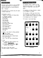
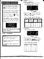
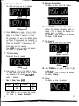
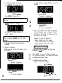
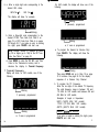
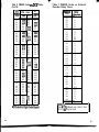
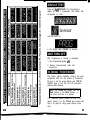
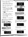
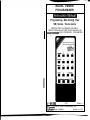
MODEL PM4500
PROGRAMMER
Programming Mini-Corn@ Plus
SM Series Transceivers
RESTRICTED TO DEALER USE ONLY.
USE BY PERSONS OTHER THAN DEALERS IS
8NAUTHORlZED
AND EXPRESSLY PROHIBITED.
ESCWE moQE OEUSE ENTER
mmmm
‘001-l 641-905
6-93
Section V
4Copyright 1993 by RELM Communications, Inc.
duplication strictly prohibited.
Printed in U.S.A.
Welcome to the RELM Communications family of
professional two-way radios and systems, and thank
you lor purchasing one of our fine products. We
are confident that you will be pleased with this
product and that it will provide you many years of
dependable, trouble-free communications.
Formerly known as Regency Electronics, Inc.,
RELM Communications, Inc., is a U.S. manufacturer
of two-way FM radio products. We are backed by
more than 40 years of experience in the electronic
communications industry and have earned a
worldwide reputation for providing dependable,
hard working products at a fair price.
You may remember us as Symmetric&
or Wilson, or
as Regency Land Mobile. Your first experience with
us may have been with crystal based mobile and
portable radios. We were pioneers in the development of synthesized radios, incorporating built-in
tone signalling options such as CTCSS, DCS and
Two-Tone Sequential and a host of user friendly
operational features, like scanning and keyboard
control. Our innovation in commercial radio
continues today with the introduction of an
/NSTANT
PRlORlTTM
button, a reversible display
and area grouping of channels.
We are truly a commercial communications
company with a dedicated commitment to two-way
radio design, manufacturing, sales and service. We
have selected a new name - a name which bolsters
our position as a communications company and
symbolizes our steadfast commitment to the land
mobile industry.
REJM
COYYUNlCATtONS
Our nationwide network of authorized dealers
assures that you will receive prompt, high quality
service for all your RELM products. For more
information about our products or how we can meet
your special applications, please call us at l-800821 -2900.
11’
AN
ADAGE
COMPANY
l-SL & PT Series Instruction Manual (PM 7001.1841-901)
l-RM Series Instruction Manual (P/N 7001-l 841-902)
l-RSP Series Instruction Manual (P/N 7001-l 841-903)
l-LMV2548 Instruction Manual (P/N 7001-1841-904)
l-SM Series Instruction Manual (P/N 7001-l 841-905)
Please read this manual thoroughly
before proceeding to program a SM Series Radio.
IMPORTANT:
Introduction ....................................................................... 2
Programmer Details ........................................................ 3
Preliminaries (Start-up) .................................................. 5
Programming Procedure ................................................ 6
Options Parameters ................................................... 6
Transmit Time Out Timer (TOT) .......................... 7
Scan Delay ............................................................ 7
Priority Delay ........................................................ 8
Key Pad Beep ........... . ........................................... 8
Channel 1 Beep .................................................... 8
Off Hook to Priority Channel ............................. 9
Off Hook Scan ...................................................... 9
Power Up on Channel l...................................... 1 0
TX Carrier Delay.. ................................................. 1 0
Message Annunciator.. ...................................... 1 1
Talk Around ........................................................... 1 1
Range .....................................................................
1 1
Channel Parameters .................................................. 13
Channel A c c e s s ................................................... 13
Receive Frequency ............................................ 1 4
RX BCL and Tone Code ..................................... 1 5
Transmit Frequency ............................................ 1 6
TX Tone Code ....................................................... 1 8
Display Sequence During Channel Programming.... 24
Display Test ...................................................................... 25
Unit Turn Cff ..................................................................... 25
Cloning Procedure .......................................................... 25
Transferring Data into the Programmer (Read) .... 26
Transferring Data into the Transceiver (Write) .... 27
Programming w i t h a P C .................................................. 28
N o t e s (Blank Form) ......................................................... 28
1
This manual contains instructions for using the PM4500
Programmer (simply referred to as the Programmer) to
program the Mini-Corn@ Plus 16 and 99 Channel SM
Series Transceivers.
The Programmer has a non-volatile memory that requires
no battery to maintain data.
The Programmer is used for:
1. Assigning to the Transceiver the following Options
or Configuration Parameters:
n Transmit Time-Out Timer
n Scan Delay
n Priority Delay
n Key Pad Beep
n Channel 1 Beep
n Off Hook to Prioriiy Channel
n Off Hook Scan
n Power Up on Channel 1
n TX Carrier Delay
n Message Annunciator
n Talk Around
n Range
2. Assigning to each channel the following parameters:
4 Receive Frequency
n Busy Channel Lockout (BCL)
n RX’ Tone, DCS’ Code or External Decoder
n Transmit Frequency
n TX’ Tone, DCS’ Code or External Encoder
The Programmer contains a keyboard (see Figure
below) with 20 keys arranged in a 4 x 5 matrix. A 6character LCD* display lights up when power is
applied.
All Programming and Cloning information is indicated
on the Programmer’s LCD display.
The Unit operates on 12VDC power from the Transceiver. Data between the Programmer and the Transceiver is transferred through a modular plug connected
to the Microphone jack on the Transceiver.
*LCD stands for Liquid Crystal Display
CHANNEL 1
mm
OPTIONS
m
4
m
SIMPLEX
mi
CLONE
V CHANNEL A
mh
3. Cloning:
n Transferring data from the Transceiver to the
Programmer (ReadOperation)
n Transferring data from the Programmer to the
Transceiver (Write Operation)
‘DCS stands for Digital Coded Squelch
RX stands for Receive: TX stands for Transmit
ESCAPE TOGGLE
mm
DELETE
urn
KEYBOARD
ENTER
A description of the 20 keys follows:
CHANNEL
Press this key and a digit key(s) to access a channel.
OPTIONS
Use this key for programming and reviewing the
Options Parameters.
SIMPLEX
This key is NOT functional for the SM Series Transceivers.
CLONE
This key is used for transferring or cloning data from
the Transceiver to the Programmer, or from the
Programmer to the Transceiver.
ESCAPE
Press this key to abort or leave a programming function and to check the Programmer’s display.
v
Use this key to go to the next lower channel. The
new channel’s number will be displayed.
o-9
These are digit (numeral) keys. Use these for
entering numerical data or selecting a channel.
Whether you are programming or cloning, start with
the following 4 steps:
1. Turn the Transceiver OFF.
2. Connect the modular plug from the Programmer to
the Microphone jack of the Transceiver. You will
hear a c/i& when the modular plug is fully seated.
3. a. Turn the Transceiver ON. Its display will
TOGGLE
Press this key to change Y (Yes) to N (No) and
vice-versa.
DELETE
Use this key to delete numerical data priorto
pressing ENTER, or to delete a channel.
ENTER
Use this key to complete an operation. Press this key
to store the displayed information into the memory of
the Transceiver and/or to advance to the next parameter for a selected channel. Also, use this key for
reviewing the Transceiver’s channel data or Options
Parameters. In addition, press this key to answer
Yes to any prompt that is displayed as a question.
A
Use this key to go to the next higherchannel. The
new channel’s number will be displayed.
b. The display on the Programmer should first
and then
4. The Unit is now ready to program the Transceiver.
NOTES:
1. Each time a Programmer key is pressed, a
beep will be heard if an external speaker is
plugged into the SM Series Transceiver.
2. If an invalid number is tried, the Programmer
will simply not accept it. A Beep will still be
heard, Indicating a key has been pressed.
3. Use the A for stepping up (or v for stepping
down) to the next channel.
4. Press ESCAPE to abort any programming
function or to stop. Display will momentarily
show the Display Test pattern (see page 25)
and then:
5. It is recommended that you program the Options
Parameters before programming the individual
Channel Parameters.
OPTIONS
Blinking - T
2. Enter a value 0 - 7 (see Table 1 below). Press
ENTER to store TOT in memory and advance
the display to Scan Delay.
Table 1. Transmit Time-Out (TOT) Values.
Numeral
TOT
(Seconds)
Numeral
TOT
(Minutes;
3. Scan Delay.
Display will show, for example:
PARAMETERS
NOTES:
1. These parameters pertain to the Unit as a
whole, not for a specific channel.
2. If an error is made in entering the data, press
DELETE and start over.
3. To REVIEW the Options, repeatedly press
OPTIONS.
6
OPTIONS
(Continued)
1. Press OPTIONS. The display will show the
Transmit Time-Out Timer. For example:
Blinking 2
4. Enter a value 0, 1, 2 or 3. (See Table 2 below.)
Press ENTER to store Scan Delay in memory
and advance the display to Priorlty Delay.
Table 2. Delay Values (Seconds).
10. Press TOGGLE key to toggle Y (Yes) to N (No)
or vice versa.
Press ENTER to store in memory and advance
the display to Off Hook to Priority Channel.
5. Priority Delay.
Display will show, for example:
11. Off Hook to Priority Channel.
The display will show one of the following:
B/inking 2
6. Enter a value 0, 1, 2 or 3. (See Table 2, page 7.)
Press ENTER to store Priority Delay in memory
and advance the display to Key Pad Beep.
7. Key Pad Beep.
The display will show one of the following:
Blinking 2
Blinking -d
Blinking
T
Blinking
I-
12. Press TOGGLE key to toggle Y (Yes) to N (No)
or vice versa.
Press ENTER to store in memory and advance
the display to Off Hook Scan.
13. Off Hook Scan.
The display will show one of the following:
8. Press TOGGLE key to toggle Y (Yes) to N (No)
or vice VBTSP.
Press ENTER to store in memory and advance the
display to Channel 1 Beep.
9. Channel 1 Beep.
The display will show one of the following:
Blinking 2
Blinking
Blinking 2
Blinking
8
T
14. Press TOGGLE key to toggle Y (Yes) to N (No)
or vice versa. If Yes is selected, the Off Hook
to Priority Channel (Step 11) Yes selection
is disregarded.
Press ENTER to store in memory and advance
the display to Power Up on Channel 1.
9
15. Power Up on Channel 1.
The display will show one of the following:
19. Message Annunciator.
The display will show one of the following:
Blinking 2
20. Press TOGGLE key to ON or OFF. If ON is
Blinking 3‘
16. Press TOGGLE key to toggle Y (Yes) to N (No)
or vice versa. If Yes is selected, the Radio will
always be on Channel 1 whenever it is turned
ON (powered-up). If it was in the MANUAL Mode
on Channel 13 (for example) when turned OFF, it
will power-up on Channel 1. If it was in the SCAN
Mode when turned OFF, it will power-up in the
SCAN Mode and start scanning.
Press ENTER to store in memory and advance
the display to TX Carrler Delay.
17. TX Carrier Delay.
Display will show, for example:
18. Enter a value 0, 1, 2 or 3. (See Table 3, below.)
TX Carrier Dleay is the amount of time the carrier
(no modulation) is still present afferthe Pll
switch is released.
Table 3. Delay Values (mS).
Delay
165
300
Numeral
2
3
Delay
400
500
Press ENTER to store in memory and advance
the display to Message Annunciator.
10
21. Talk Around.
The display will show one of the following:
Blinking 2
Blinking 1
Numeral
0
1
selected, the Message Annunciator feature is
enabled. If OFF is selected, the Message Annunciator feature is disabled.
Press ENTER to store in memory and advance
the display to Talk Around.
t
Blinking
22. Press TOGGLE key to toggle Y (Yes) to N (No)
or vice versa.
Press ENTER to store in memory and advance
the display to Range.
23. Range.
The display will show, for example:
WARNING: The Transceiver’s proper Range is
determined at the time of manufacture. It should
NOT be programmed unless components that
affect the Unit’s memory have been replaced. It
should never be changed to a different value.
a. If programming is necessary, key in the proper
value. See Table 4, below.
b. Press ENTER to store Range number in the
Transceiver’s memory. The display will return
to the. start of Options and show Transmit
Time-Out Tlmer.
CAUTION: If the Range number is changed, the
display will show, for example:
CHANNEL PARAMETERS
NOTES:
1. Programming steps should be performed
in the following order as shown.
2 . It is recommended that Channel Parameters
be programmed after you have programmed
the Options Parameters.
3. See page 24 for examples of programmed
channels.
1. Channel Access
Press CHANNEL.
The display will show:
Blinking 1
After ENTER is pressed, the display will return
to the start of Options. All channels are changed
to invalid frequencies. Thus, each channel to be
used will have to be programmed again for its
prooer receive and transmit frequency.
L Blinking
2. Press the desired Channel’s Number (1 - 9; 10 - 16
or 10 - 99). The display will show, for example:
Table 4. Ranges
T
If:
Y = ?,
REVIEWING PROGRAMMED DATA
You may wish to review the Options Data you entered
into the Unit.
After Step 23 on page 11, press OPTIONS in succession to step through the Options Parameters.
T Blinking
Channel has both a Receive and a
Transmit frequency.
Y= R,
Receive on/y. Hence, it can’t transmit.
See page 17 for procedure.
Y= D,
Channel is deleted. Hence, it has no
receive or transmit frequency.
For UHF models, the display will show one of the
following:
a. To delete the channel at this time,
press DELETE. The display will show:
Blinking - I
Press ENTER to answer Yes.
- Blinking
if previously
programmed
NOTE: To answer No, press TOGGLE or any
diait kev.
Disolav will show, for example:
Blinking
or, if none is programmed
4. Key
The
174
482
See page 24 for display sequence of a
deleted channel.
NOTE: If you make an error in number entry, start
over by pressing CHANNEL and the correct
number.
Examples of keyed in frequencies:
56045 (158.045 MHz; VHF models)
167237 (167.2375 MHz; VHF models)
470012 (470.0125 MHz; UHF models)
b. To step to Receive Frequency, press
ENTER.
NOTE: Ignore the decimal.
3. Receive Frequency
Display will show, for the VHF models, one of
the following:
If an error is made in entering the digits, press
DELETE and start over.
P
-f Blinking
if previously programmed
in the six digits of the desired RX frequency.
valid frequency range is between 150 and
MHz for VHF models and between 450 and
MHz for UHF models.
i
Press ENTER to store the Receive Frequency in
the Transceiver’s memory. The display will advance
to RX BCL and Tone Code.
5. RX BCL and Tone Code
Display will show, for example:
I- Blinking
- Blinking
or, if none is programmed
14
L Tone Code
BCL Code
15
t
6. a. Enter a single digit code corresponding to the
desired BCL status.
BCL No = 0
For UHF models, the display will show one of the
following:
BCL Yes = 1
The display will show, for example:
T
- Blinking
b. Enter a three-digit code corresponding to the
desired CTCSS Tone Code from Table 5 on
page 19 or DCS Code from Table 6 on pages
20 through 22. If you make an error in entering
the digits, press DELETE and start over.
NOTE: External Decode is selected by entering 155 or higher (up to 169) for the RX Tone
Code. See Table 7 on page 23.
Blinking
if previously programmed
Blinking
or, if none is programmed
a. To program the channel for Receive Only:
Press DELETE. The display will show the
following:
c. Press ENTER to store the RX BCL and Tone
Code in the Transceiver’s memory and to
advance the display to Transmit Frequency.
7. Transmit Frequency
Display will show, for VHF models, one of the
following:
- Blinking
if previously programmed
Blinking
Then press ENTER and go to Step 10 on page
18 to continue. See page 24 for the display
sequence of a Receive Only Channel.
b. To program the TX Frequency:
Enter the six digits of the desired TX frequency.
The valid frequency range is between 150 and
174 MHz for VHF models and between 450 and
462 MHz for UHF models.
Examples of keyed in frequencies:
54010 (154.010 MHz; VHF models)
171312 (171.3125 MHz; VHF models)
460775 (460.775 MHz; UHF models)
l-- Blinking
or, if none is programmed
16
NOTE: lanore the decimal.1
If an error is made in entering the digits, press
DELETE and start over.
17
Press ENTER to store Transmit Frequency in
memory. The display will advance to TX Tone
Code. 8. TX Tone Code
Display will show, for example:
Not programmable; it 1‘ -f Blinking
will always be the same
as the RX BCL Code
9. Enter a three-digit code corresponding to the
desired CTCSS Tone Code from Table 5 on
page 19 or DCS Code from Table 6 on pages 20
through 22.
NOTE: External Encode is selected by entering
155 (or higher, up to 189) for the TX Tone Code.
See Table 7 on paae 23.
I
If you make an error In entering digits, press
DELETE and start over.
Table 5. PM4500 C:odes vs. CTCSS Tones.
Code
#
000
001
002
003
004
005
006
007
008
009
010
011
012
013
014
015
016
TONE
U-W
No Tone
67.0
71.9
74.4
77.0
79.7
82.5
85.4
88.5
91.5
94.8
97.4
100.0
103.5
107.2
110.9
114.8
Code
#
TONE
(Hz)
Zode
#
TONE
(Hz)
017
018
019
020
021
022
023
024
025
026
027
028
029
030
031
032
033
118.8
123.0
127.3
131.8
136.5
141.3
146.2
151.4
156.7
162.2
167.9
173.8
179.9
186.2
192.8
203.5
210.7
034
035
036
037
038
039
040
041
042
043
044
045
046
047
048
049
050
218.1
225.7
233.6
241.8
250.3
69.4
159.8
165.5
171.3
177.3
183.5
189.9
196.6
199.5
206.5
229.1
254.1
Press ENTER to store TX Tone Code in the
Transceiver’s memory. The display will return to
showing the channel number.
10. For other channels, repeat procedural steps 1 9, or repeatedly press CHANNEL A (or ‘I) to
step to the next desired channel.
Reviewing Programmed Data
You may wish to review the data you have entered
into a channel. There are two methods for doing this.
1. After step 9 above, press ENTER in succession
to step through the channel’s parameters.
2. Press CHANNEL and the desired channel’s
number. Then press ENTER in succession to
step through the desired channel’s parameters.
NOTE (Concerning Table 6 that follows on
pages 20,21 and 22): For communication
systems utilizing only SM Series transceivers, it
is recommended that Standard PM4500 DCS
(Standard DCS) codes be used. For existing
communication systems employing DCS, it may
be necessary to use the Inverted (or complemented) DCS and corresponding PM4500 Code
for proper Transceiver operation.
NOTE: See page 24 for a summary of display
sequences during channel parameters
programming.
18
19
Table 6. PM4500
Codes ws. DCS* Codes.
Table 6. PM4500 Codes vs. DC!2
(Cont’d).
STD
‘h+l4500
coda
DCS Code
JV
STD
INV
‘M450
051
052
053
054
055
023
025
026
031
032
147
144
64
i27
I51
058
090
127
141
059
223
225
226
243
244
z:
074
070
115
110
052
056
057
068
059
080
E
047
051
063
72
145
)23
)32
I52
082
121
051
055
123
245
246
251
252
255
072
523
165
462
446
064
133
061
126
122
061
062
083
084
065
054
086
071
072
073
I13
271
117
100
102
091
131
261
263
265
732
205
156
454
065
151
x:
088
069
070
074
114
115
116
122
083
148
077
154
087
071
072
073
074
075
125
131
132
134
143
174
712
152
754
225
365
364
546
223
412
113
112
136
086
116
106
107
108
109
110
076
077
078
079
080
145
152
155
156
162
274
115
731
265
503
101
068
050
098
130
111
112
113
114
115
081
082
083
165
172
174
205
212
251
036
074
093
056
066
097
111
116
117
118
119
120
xii
l
DCS Code
iii
508
-
it:
DCSstandsforDigitalCodedSquelch.
Table 6 continued on next page.
oii
098
099
100
Efi
274
%i
124
145
071
664
423
526
076
063
146
118
134
465
455
zz
243
128
125
135
139
089
ii:
371
411
212
131
125
734
226
085
072
071
152
088
412
413
423
431
432
143
054
315
723
516
075
061
104
149
132
E
315
325
l
134
122
411
356
Codes
DCS stands for Digital Coded Squelch,
Table 6 continued on next page.
Table 6. PM4500 Codes ws. DCS’ Codes
(Cont’d).
DCS Code
121
122
123
124
125
126
127
128
129
130
131
132
133
134
135
?4:
452
454
455
ii:
465
466
503
z:
523
526
532
136
137
138
139
140
INV
code
043
255
053
057
z:
252
026
627
E
099
107
z:
162
i!:
106
145
080
073
432
246
325
343
065
120
092
105
108
132
703
073
147
142
ii:
632
141
142
143
144
145
INV
iii
ii:
654
662
031
808
624
743
466
054
138
140
153
129
146
147
148
149
150
664
703
712
723
731
311
565
114
431
155
103
137
067
119
078
151
152
153
154
732
734
743
754
E1
654
116
096
114
144
089
* DCSstandsforDigitalCodedSquelch.
Table 7. PM4500 Codes vs. External
Decoder Delay Times
I PM4500
Code
155
156
157
158
159
160
161
162
163
164
165
166
167
168
169
170
171
172
173
174
175
176
177
178
179
180
181
182
183
184
185
186
187
188
189
0
0.1
0.2
0.3
0.4
0.5
0.6
0.7
0.8
0.9
1.0
1.1
1.2
1.3
1.4
1.5
1.6
1.7
1.8
1.9
2.0
2.1
2.2
2.3
2.4
2.5
2.6
2.7
2.8
2.9
3.0
3.1
3.2
3.3
3.4
NOTE:To enable an Encoder (TX), use
Code #155, although any Code # from
155 to 169 may be used.
23
Press and hold ESCAPE. The Programmer’s
display will show a characteristic Test Pattern with
all segments on, thus:
and then revert to:
in the display when ESCAPE is released.
After Programming or Cloning is completed:
1. Turn Transceiver power off.
2. Remove inter-connecting cable from
transceiver.
This feature permits duplicating (cloning) the same
programmed data into any number of transceivers.
Be sure to use the proper Start-up (see PRELIMINARIES, page 5) and Unit Turn Off procedures
(above) when cloning.
NOTE: The CLONE key toggles from the
Read function to the Wrlte function, or
vice versa, each time it is pressed.
If a Transceiver a/ready contains the data to be
cloned, connect it to the PM4500 and proceed with
Step 3 on page 26, using proper Start-up procedure.
24
25
If the data to be duplicated (cloned) is NOT already
in a Transceiver, proceed as follows:
3. When transfer is complete, the display will
show:
1. Connect the PM4500 to the Transceiver to be
programmed using proper Start-up procedure.
2. Enter the data into the transceiver by using the
PM4500 normal programming functions.
3. Press CLONE.
If “READ?” is in the display, press ENTER. If
not, press CLONE again and then ENTER.
This will copy the Transceiver’s entire data into
the Programmer’s memory.
4. Turn OFF the Transceiver and then disconnect
the PM4500.
5. Connect the PM4500 to a Transceiver to be
cloned, using proper Start-up procedure.
6. Press CLONE (“WRITE?” must be in the display) and then ENTER.
m!iibiw
TRANSFERRING DATA /NT0 THE
TRANSCEIVER ( WRlTE OPERATION)
1. Press CLONE. Display will show:
Blinking
2
NOTE: If not, press CLONE again.
2. Press ENTER (to answer Yes).
Processing will begin. During data transfer, the
display will show:
7. Repeat steps 4, 5 and 6 for all other Transceivers to be cloned.
A detailed description of the CLONE (READ and
WRITE) operations follows:
TRANSFERRING DATA MT0 THE
PROGRAMMER (READ OPERATION)
1. Press CLONE. Disolav will show:
1 NOTE: If not, pr::iztNE<n.
]
2. Press ENTER (to answer Yes).
Processing will begin. During data transfer, the
display will show:
26
NOTE: If you attempt to transfer SM (for example)
Series data in the Programmer to a different series
Radio (such as PT, RSP, etc.), the display will
show:
The Transceiver will emit a series of beeps and
no transfer will take place.
3. When transfer is complete, the display will show:
27
An IErM@ PC-compatible computer with a serial
port can be used for all programming and cloning
functions the same as the PM4500. Consult the
factory for details of the menu-driven software
and the necessary Interface Adapter required
between the PC and an SM Series Transceiver. A
modular coupler can be used for connecting the
Interface Adapter’s cable to the PM4500. This
coupler is stored in the Programmer’s rear panel
compartment.
Programming the Transceiver is accomplished
through its microphone jack. The software provides for a pre-formatted print out of all information programmed into the Transceiver.
NOTES:
I