1
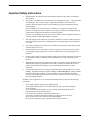
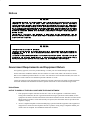
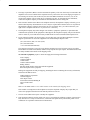
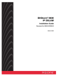
You have accessed an older version of a
Paradyne product document.
Paradyne is no longer a subsidiary of
AT&T. Any reference to AT&T Paradyne
is amended to read Paradyne
Corporation.
AREA CODE CHANGE
Please note that the area code for
Paradyne Corporation in Largo, Florida
has changed from 813 to 727.
For any Paradyne telephone number that
appears in this manual with an 813 area
code, dial 727 instead.
Paradyne
COMSPHERE 3900 Series Modems
Models 3920Plus and 3921Plus
Installation Instructions
Document Number 3920-A2-GK41-10
April 1995
Overview
The COMSPHEREr 392xPlus modems include an integral time division multiplexer (TDM) with a modem
sharing device (MSD) as standard equipment. The TDM provides time division multiplexing of up to four
independent ports over point-to-point lines using the V.34 family or V.32 family modulation. The MSD allows
multiple physical ports on a tributary modem to share a single communication channel using the V.34 family,
V.32 family or TMp modulation. These modems operate over leased-line or dial networks. The multiplexer (mux)
can be enabled or disabled to allow a greater degree of application flexibility. This document provides the
following information:
• Important safety instructions
• Regulatory notices
• Government requirements and equipment return information
• A description of the COMSPHERE 392xPlus models
• A list of equipment supplied with the modem
• A list of customer supplied equipment
• Installation instructions
This document is intended to be used in conjunction with the COMSPHERE 3900 Series Modems,
Models 3920Plus and 3921Plus, Installation and Operation Manual, Document No. 3920-A2-GN31.
Ordering Information
To order AT&T Paradyne documentation, please call 1-800-545-2354, extension 2222.
1
Important Safety Instructions
1.
Read and follow all warning notices and instructions marked on the product or included in
this document.
2.
This product is intended to be used with a three-wire grounding type plug — a plug which has
a grounding pin. This is a safety feature. Equipment grounding is vital to ensure safe
operation. Do not defeat the purpose of the grounding type plug by modifying the plug or
using an adapter.
Prior to installation, use an outlet tester or a voltmeter to check the ac receptacle for the
presence of earth ground. If the receptacle is not properly grounded, the installation must not
continue until a qualified electrician has corrected the problem.
If a three-wire grounding type power source is not available, consult a qualified electrician to
determine another method of grounding the equipment.
3.
Slots and openings in the cabinet are provided for ventilation. To ensure reliable operation of
the product and to protect it from overheating, these slots and openings must not be blocked
or covered.
4.
Do not allow anything to rest on the power cord and do not locate the product where persons
will walk on the power cord.
5.
Do not attempt to service this product yourself, as opening or removing covers may expose
you to dangerous high voltage points or other risks. Refer all servicing to qualified service
personnel.
6.
General purpose cables are provided with this product. Special cables, which may be required
by the regulatory inspection authority for the installation site, are the responsibility of the
customer.
7.
When installed in the final configuration, the product must comply with the applicable Safety
Standards and regulatory requirements of the country in which it is installed. If necessary,
consult with the appropriate regulatory agencies and inspection authorities to ensure
compliance.
8.
A rare phenomenon can create a voltage potential between the earth grounds of two or more
buildings. If products installed in separate buildings are interconnected, the voltage potential
may cause a hazardous condition. Consult a qualified electrical consultant to determine
whether or not this phenomenon exists and, if necessary, implement corrective action prior to
interconnecting the products.
In addition, if the equipment is to be used with telecommunications circuits, take the following
precautions:
–
–
–
–
–
–
Never install telephone wiring during a lightning storm.
Never install telephone jacks in wet locations unless the jack is specifically designed
for wet locations.
Never touch uninsulated telephone wires or terminals unless the telephone line has
been disconnected at the network interface.
Use caution when installing or modifying telephone lines.
Avoid using a telephone (other than a cordless type) during an electrical storm.
There may be a remote risk of electric shock from lightning.
Do not use the telephone to report a gas leak in the vicinity of the leak.
2
Notices
" " " " " " ! " "" ! Government Requirements and Equipment Return
For regulatory approval, refer to the product labeling or contact your local AT&T Paradyne representative.
For the 3900 Series standalone modems, the Universal Service Order Code (USOC) for Permissive mode is
RJ11C. The Canadian equivalent to RJ11C is CA11A. For 3900 Series carrier-mounted modems, the USOC for
Permissive mode is RJ21X. The Canadian equivalent to RJ21X is CA21A.
Certain governments require that instructions pertaining to modem connection to the public switched telephone
network be included in the installation document. Specific instructions are listed in the following sections.
United States
NOTICE TO USERS OF THE PUBLIC SWITCHED TELEPHONE NETWORK
1. This equipment complies with Part 68 of the FCC rules. On the equipment is a label that contains,
among other information, the FCC registration number and ringer equivalence number (REN) for this
equipment. The label is located on the bottom of the Model 3920Plus modem. This label is located on the
Model 3921Plus modem’s circuit card assembly. If requested, this information must be provided to the
telephone company.
2. An FCC compliant telephone cord and modular plug is provided with this equipment. This equipment is
designed to be connected to the telephone network or premises wiring using a compatible modular jack
which is Part 68 compliant. See Installation Instructions for details.
3
3. The ringer equivalence (REN) is used to determine the quantity of devices which may be connected to the
telephone line. Excessive RENs on the telephone line may result in the devices not ringing in response to
an incoming call. In most, but not all areas, the sum of the RENs should not exceed five (5.0). To be
certain of the number of devices that may be connected to the line, as determined by the total RENs,
contact the telephone company to determine the maximum RENs for the calling area.
4. If the 392xPlus modem causes harm to the telephone network, the telephone company will notify you in
advance that temporary discontinuance of service may be required. But if advance notice is not practical,
the telephone company will notify the customer as soon as possible. Also, you will be advised of your
right to file a complaint with the FCC if you believe it is necessary.
5. The telephone company may make changes in its facilities, equipment, operations, or procedures that
could affect the operation of the equipment. If this happens, the telephone company will provide advance
notice in order for you to make the necessary modifications in order to maintain uninterrupted service.
6. If your 392xPlus modem is in need of repair, you can either call your local AT&T Paradyne Customer
Support representative or return the equipment to the AT&T Paradyne Repair Center.
(813) 530-2268 or (800) 772-7691 (USA)
(813) 530-8690 (FAX)
+1 813 530-8099 (International)
The Customer Assistance Center will verify that the equipment is in need of repair. You are provided a
Return Material Authorization (RMA) number to help expedite the repair request. The RMA number must
be clearly marked on the outside of the shipping carton.
To return the equipment, prepare a memo and supply the following information:
Your Company
Company Address
Contact Name
Contact’s Phone Number
Billing Address
Purchase Order Number Associated with the Equipment
Brief Description of the Symptoms
Package the equipment carefully for shipping, including the memo containing the necessary information,
and send to the address below:
AT&T Paradyne Corporation
Customer Support
Attn: Repair Center
8550 Ulmerton Road, Building B
Largo, Florida 34641
USA
Make sure the RMA number is in a visible location on the outside of the shipping carton.
If the trouble is causing harm to the telephone network, the telephone company may request that you
remove the equipment from the network until the problem is resolved.
7. The user is not authorized to repair or modify the equipment.
8. This equipment cannot be used on public coin service provided by the telephone company. Connection to
Party Line Service is subject to state tariffs. (Contact the state public utility commission, public service
commission or corporation commission for information.)
4
Canada
NOTICE TO THE USERS OF THE CANADIAN PUBLIC SWITCHED TELEPHONE NETWORK
The Canadian Department of Communications label identifies certified equipment. This certification means that
the equipment meets certain telecommunications network protective, operational and safety requirements. The
Department does not guarantee the equipment will operate to the user’s satisfaction.
Before installing this equipment, users should ensure that it is permissible to be connected to the facilities of the
local telecommunications company. The equipment must also be installed using an acceptable method of
connection. In some cases, the company’s inside wiring associated with a single line individual service may be
extended by means of a certified connector assembly (telephone extension cord). The customer should be aware
that compliance with the above conditions may not prevent degradation of service in some situations.
Repairs to certified equipment should be made by an authorized Canadian maintenance facility designated by the
supplier. Any repairs or alterations made by the user to this equipment, or equipment malfunctions, may give the
telecommunications company cause to request the user to disconnect the equipment.
Users should ensure for their own protection that the electrical ground connections of the power utility, telephone
line and internal metallic water pipe system, if present, are connected together. This precaution may be
particularly important in rural areas.
CAUTION
Users should not attempt to make such connections
themselves, but should contact the appropriate electric
inspection authority, or electrician, as appropriate.
The Load Number is labeled on the equipment. The Load Number (LN) assigned to each terminal device denotes
the percentage of the total load to be connected to a telephone loop which is used by the device to prevent
overloading. The termination on a loop may consist of any combination of devices subject only to the requirement
that the total of the Load Numbers of all devices does not exceed 100.
If your equipment is in need of repair, contact the AT&T Paradyne Regional Sales Office nearest you. If you
are unable to contact a regional sales office, arrange to have your equipment repaired by contacting Inventory
Control Office, 100 York Blvd., Suite 200, Richmond Hill, Ontario L4B 1J8, telephone (905) 709-5000.
5
COMSPHERE 392xPlus Models
The 392xPlus family is available in two models: the Model 3920Plus, a 4-wire/2-wire standalone modem, and the
Model 3921Plus, a carrier-mounted version of the standalone unit.
Standalone Model 3920Plus 4-Wire/2-Wire Modem
The standalone Model 3920Plus modem (Figure 1) is capable of either 4-wire/2-wire leased-line or dial
operation. The modem is controlled using the diagnostic control panel (DCP). The DCP consists of a liquid
crystal display (LCD), three function keys, four directional keys, and a row of 13 LED status indicators. For a
better understanding of DCP operation, refer to Chapter 3, DCP Operation, in Document No. 3920-A2-GN31.
The rear of the modem contains an ON/OFF power switch, a low voltage dc power connector, an 8-pin modular
connector for leased-line connection, an 8-pin modular connector for dial-line connection, a 4-pin modular
connector for network management, and four DTE connectors.
Figure 1. Model 3920Plus
6
Carrier-Mounted Model 3921Plus 4-Wire/2-Wire Modem
The carrier-mounted Model 3921Plus modem (Figure 2) installs into a COMSPHERE 3000 Series Carrier. The
Model 3921Plus modem’s faceplate covers two slots in the carrier. It has 20 LED status indicators for displaying
modem activity and an audio speaker jack for the carrier’s optional speaker.
The Model 3921Plus modem’s rear has four edge card connectors that mount into two connector plates located on
the rear of the carrier. Each connector plate has two DB-25-S connectors providing four EIA-232-D DTE
interfaces.
Figure 2. Model 3921Plus
7
The Model 3921Plus derives ac power from the COMSPHERE 3000 Series Carrier’s backplane, which is a
common bus to all devices installed in the carrier. The user interface to any Model 3921Plus is through the shared
diagnostic control panel (SDCP), an optional feature which operates in a manner similar to the DCP on the
Model 3920Plus. For a better understanding of DCP operation, refer to Chapter 3, DCP Operation, in Document
No. 3920-A2-GN31.
The COMSPHERE 3000 Series Carrier has a total of 17 slots. The first slot, Slot 0, is reserved for the shared
diagnostic unit (SDU) while the remaining 16 slots can house up to 8 Model 3921Plus modems, or a combination
of Model 3921Plus modems and other units. For more details on the COMSPHERE 3000 Series Carrier, refer to
the COMSPHERE 3000 Series Carrier, Installation Manual, Document No. 3000-A2-GA31.
392xPlus Modem Package
After opening the modem’s package, check for damage and verify that the following items are present:
For the standalone model
• Installation instructions
• Model 3920Plus modem
• Power supply with power cord
• One 6-position, 4-wire modular cord
• One 8-position, 8-wire modular cord
For the carrier-mounted model
• Installation instructions
• Model 3921Plus modem
• Two rear connector plates with two DB-25-S edge card connectors on each plate
If any hardware components are damaged, notify your AT&T Paradyne representative. Return equipment using
the procedures described in the Government Requirements and Equipment Return section.
Customer-Supplied Equipment
The following customer-supplied equipment is required to complete a data communications system using the
Model 3920Plus modem:
• DTEs with available EIA-232-D serial ports.
• Standard EIA-232-D cables with DB-25-P (plug) connectors at one end to attach to the modem.
• One or more of the following modular leased or dial network interfaces:
— JM8 for leased-line applications.
— RJ11C for dial permissive applications.
— One 8-position, 8-wire modular cord (for leased backup purposes).
8
The following customer-supplied equipment is required for the installation of a Model 3921Plus modem:
• A COMSPHEREr 3000 Series Carrier.
• A 50-pin mass termination cable.
• One of the following modular or 50-pin leased or dial network interfaces:
— RJ11C for single line dial permissive applications
— RJ21X for multiple line dial permissive applications
— 66 punchdown block
• One Network Interface Module (NIM) for modems installed in Slots 1–8 and one NIM for modems
installed in Slots 9–16 (required for dial-line applications).
For installation of the COMSPHERE 3000 Series Carrier into a cabinet, refer to the COMSPHERE 3000 Series
Carrier, Installation Manual, Document No. 3000-A2-GA31.
Model 3920Plus Input Voltage Requirements
The power supply used with the Model 3920Plus modem (Figure 3) is auto-sensing and capable of operating
(without reconfiguration) with input voltages from 100 Vac to 250 Vac, and input frequencies from 50 Hz to
60 Hz.
Model 3920Plus Modem Installation
Before installing your standalone modem, make sure your installation site is clean and well-ventilated. Allow
space around the modem for installing cables and telephone cords, and make sure the modem is located within
reach of the ac power outlet. The distance between your modem and DTE should be minimized if DTE data rates
exceed 19,200 bps. Also, low capacitance cables may be necessary for speeds greater than 19,200 bps or distances
greater than 50 feet.
The rear panel of the Model 3920Plus modem (Figure 3) has the following switches and connectors:
• An ON/OFF power switch.
• An 8-pin DIN type power receptacle for the dc power supply.
• An 8-pin modular keyed jack (Lease) for 4-wire/2-wire leased lines.
• An 8-pin modular keyed jack (Dial) for backup lines (2-wire dial or 2-wire lease).
• A 4-pin modular jack for the Network Management System (NMS) connection.
• Four 25-pin DB-25-S receptacles for the DTE interfaces.
9
Connecting Model 3920Plus Modems with Supplied Cables
Figure 3 shows how Model 3920Plus modems are connected to certain TELCO jack types using the appropriate
cables.
DTE 2
DTE 3
LEASED DIAL
8-POSITION,
8-CONDUCTOR
PLUG FOR
LEASED-LINE
NETWORK
OPERATION
6-POSITION,
4-CONDUCTOR
PLUG FOR
PERMISSIVE
DIAL
NETWORK
OPERATION
DTE 1
DTE 4
NMS
PWR
ON OFF
DB-25-P
CONNECTOR
FOR DATA
TERMINAL
EQUIPMENT
OPERATION
SUB-MINIATURE,
4-CONDUCTOR
PLUG FOR
NETWORK
MANAGEMENT
SYSTEM
OPERATION
POWER
SUPPLY
POWER
CORD
NOTE: THE DIAL JACK IS ALSO USED
FOR 2-WIRE LEASED BACKUP.
Figure 3. Model 3920Plus Rear Panel and Power Supply
DTE Connection
Use the following procedures to connect an EIA-232-D cable from the modem to a DTE:
1. Make sure the modem’s rear panel power switch is OFF.
2. Connect the DB-25-P (plug) connector on the cable to the DB-25-S (socket) connector (Figure 3) on the
modem’s rear panel. Use a small screwdriver to secure the cable to the modem.
3. Connect the DB-25-P connector on the cable to the DB-25-S connector on the DTE. Use a small
screwdriver to secure the cable to the DTE.
10
Model 3920Plus 4-Wire/2-Wire Leased-Line Connection
Use the following procedures to connect a Model 3920Plus to the leased-line network interface:
1. Insert the 8-position, 8-conductor modular plug into the jack labeled LEASED (Figure 3).
2. Insert the other end of the modular cord into the leased-line network interface.
3. If the Model 3920Plus has a backup line, follow the steps listed in the Model 3920Plus Backup-Line
Connection section.
Dial Connection
The telephone company provides the line termination jacks for the permissive service you request. Advance
coordination with the telephone company is suggested when connecting the modem to telephone dial lines
(PSTN).
In the Permissive mode, the modem’s transmit output level is fixed at –9 dBm. The telephone company assumes
that the line loss is 3 dB and no compensation is provided for additional losses. A Permissive mode telephone line
is usually terminated with a USOC RJ11C jack.
Model 3920Plus Dial Backup Connection
For the Model 3920Plus, use the following procedures to connect the modem to the dial network interface:
1. Insert the 6-position, 4-conductor modular plug into the jack labeled DIAL (Figure 3).
2. Insert the other end of the modular cord into the dial network interface.
Model 3920Plus Leased Backup Connection
For the Model 3920Plus, use the following procedures to connect the modem to the 2-wire leased backup network
interface:
1. Insert the 8-position, 8-conductor modular plug into the jack labeled DIAL (Figure 1).
2. Insert the other end of the modular cord into the leased-line network interface.
Network Management System Connection
For the Model 3920Plus, use the following procedures to connect the modem to the network management system
interface:
1. Insert the sub-miniature, 4-conductor modular plug of the 3600 Hubbing Device into the jack labeled
NMS (Figure 3). Refer to Document Number, 3610-A2-GZ45, 3600 Hubbing Device Feature Number
3600-F3-300, Installation Instructions, for a description of the 3600 Hubbing Device. Installation for the
3920Plus is the same as for the 3610 DSU.
2. Connect the 3600 Hubbing Device to the network management system.
11
Power Supply Connection
Use the following procedures to connect the modem to an ac power outlet:
1. Make sure the modem’s power switch is in the OFF position.
2. Insert the power supply’s 8-pin DIN connector into the modem’s rear panel dc power receptacle
(Figure 3).
3. Connect the power cord to the power supply.
4. Connect the power cord to a grounded ac power outlet.
Modem Power-Up
Once your modem is properly connected to the power supply, leased and/or dial lines, and the DTE, press the
modem’s rear panel power switch to the ON position. The modem begins a power-up self-test in which all DCP
LEDs light. This test takes several seconds to perform, and verifies the operation of most hardware components
within the modem. If successful, the LCD displays Power on Selftst Passed and continues to the Top-Level
menu screen.
Power On Selftst
Passed
F1
F2
F3
If a failure occurs during the self-test, the LCD displays Power On Selftst Failed for several seconds. The LCD
then displays the Top-Level menu screen with the message Power on Fail appearing on the top line of the LCD.
Although a failure has occurred, the modem will attempt to operate. This allows you to activate a more thorough
self-test using the Test branch. For a better understanding of the Test branch, refer to Chapter 3, DCP Operation,
in Document No. 3920-A2-GN31.
Selecting Factory Configuration Options
After the modem passes the power-up self-test, configure it for operation using one of the six factory preset
configurations.
The purpose of having preset configurations is so that you can have a “head start” in getting your modem
operating and reduce the amount of time required to configure your modem. For a better understanding of DCP
operation and factory preset configuration options, refer to Chapter 4, DCP Configuration, in Document
No. 3920-A2-GN31.
12
Using the Diagnostic Control Panel (DCP)
The DCP’s liquid crystal display (LCD) consists of two 16-character lines which display modem status, control
functions, and configuration options as well as indicating your location in the Top-Level menu tree.
To change a factory template from the Sync Leased preset configuration using the DCP, perform the following
steps:
1. Press the function key below Configure to select the Configure branch.
The LCD now displays Ld EditArea frm.
key until Factory comes into view, then press the F1 key to display the factory preset
2. Press the
configurations.
key until the appropriate factory preset appears on the LCD, and press the corresponding
3. Press the
function key to select your choice. (For certain factory presets you will also need to choose the
appropriate mode.)
4. Choose Function appears and displays the Edit and Save functions.
5. Press the F3 key (Save) to save the new factory preset configuration to one of three configuration areas,
Active (Saved), Customer 1, or Customer 2.
(These three configuration areas are nonvolatile memory locations. Active (Saved) contains the most
recently saved changes to any configuration options. In the event of power loss, the modem retrieves these
configuration options. Customer 1 and Customer 2 are user-defined configuration areas.)
The LCD now displays Sav EditArea to.
key until the appropriate configuration area appears on the LCD, then press the
6. Press the
corresponding function key to select your choice. (Saving configuration options to the Active (Saved)
configuration area automatically saves them to the Active (Operating) configuration area.) The LCD
displays Command Complete.
7. The modem is now configured with the selected factory template. Press the
Top-Level menu.
key to return to the
Removing and Replacing Model 3920Plus Modems
To remove and replace a Model 3920Plus modem, perform the following steps:
1. Make sure the modem is offline, and press the modem’s rear panel power switch to the OFF position.
2. Disconnect the power cord from the ac power outlet, and then disconnect the dc power cable from the
connector on the rear of the modem.
3. Disconnect the dial and leased-line modular cords from the modem’s rear panel.
4. Disconnect the DTE interface cables from the modem’s rear panel.
If the modem is to be removed for service, return it to AT&T Paradyne using the procedures described in
Government Requirements and Equipment Return.
5. Install the replacement modem as described in the Model 3920Plus Modem Installation section, and
configure it the same way as the modem being replaced.
13
Model 3921Plus Modem Installation
CAUTION
If the Model 3921Plus is removed from the carrier, always use a
ground strap when handling the modem. Always store the
Model 3921Plus in an antistatic bag when it is removed from
the carrier.
The Model 3921Plus is designed for installation in a COMSPHERE 3000 Series Carrier which supplies both the
operating power and the leased and/or dial network connections. For additional information about the
COMSPHERE 3000 Series Carrier, refer to the COMSPHERE 3000 Series Carrier, Installation Manual,
Document No. 3000-A2-GA31.
The COMSPHERE 3000 Series Carrier has 17 slots which can hold up to 8 Model 3921Plus modems and one
shared diagnostic unit (SDU). The SDU is required when the modems in the carrier are controlled by an NMS, or
when multiple carriers in a cabinet configuration are to be controlled by a single shared diagnostic control panel
(SDCP). The SDCP of the COMSPHERE 3000 Series Carrier is the user interface to the Model 3921Plus modem.
A single SDCP can control up to eight carriers.
The installation of a Model 3921Plus varies slightly if an SDCP is installed on the front of the carrier. To install a
Model 3921Plus modem into the carrier without an SDCP, perform the following steps:
1. At the rear of the carrier, install the rear connector plates. Make sure the plates use the same slot position
as that intended for the modem.
Loosely fasten the plates. This allows for slight adjustments later when installing the modem.
2. At the front of the carrier, hold the modem vertically, with the latch on its faceplate in the open position,
and insert it into the top and bottom card guides of one of the odd slots numbered 1–15 (Figure 4).
Slide the modem into the slot, aligning the modem with the rear connector plates, until the backplane
connector and DTE connector seat firmly into the back of the carrier. The faceplate latch automatically
closes as you push the modem into the carrier. To lock the modem into the carrier, press the faceplate latch
until a “click” is heard.
3. If the carrier is ON, the Power LED on the faceplate of the 3921Plus lights. After several seconds the
modem completes its power-up self-test, in which all faceplate LEDs light.
Return to the rear of the carrier and tighten the rear connector plates.
14
Figure 4. Installing a Model 3921Plus Modem
If the modem is to communicate with an installed SDCP, install the modem as described above and perform the
following steps:
1. Press the
Select
key on the SDCP. The cursor appears in the slot selection entry.
2. Press the F1 ( ) or F2 ( ) key until the carrier number you want appears on the LCD.
The carrier number selection has a range of 1 to 8 since a single SDCP can control a configuration of up
to eight carriers. (This is only possible if the SDU is installed.)
3. Press the
key to position the cursor on the slot selection entry.
4. Press the F1 ( ) or F2 ( ) key until the slot number you want appears on the LCD.
5. Press the
Select
key to place the SDCP in direct communication with the selected modem.
The LCD displays the Top-Level menu for the selected modem. In addition, the Front Panel LED on the
modem’s faceplate and the OK LED on the SDCP light.
15
6. Once you have determined that the modem is installed properly and completed its power-up self-test,
rotate the circuit pack lock until it covers the faceplate latch (Figure 5) and tighten the retention screw on
the circuit pack lock. This prevents the modem from accidently being removed once it is installed in a
carrier.
7. Configure the modem as described in the Selecting Factory Configuration Options section.
Figure 5. Circuit Pack Lock
16
Removing and Replacing Model 3921Plus Modems
CAUTION
If the Model 3921Plus is removed from the carrier, always use a
ground strap when handling the modem. Always store the
Model 3921Plus in an antistatic bag when it is removed from
the carrier.
It is not necessary to power down the carrier to remove and replace a Model 3921Plus modem. Perform the
following steps:
1. Rotate the circuit pack lock until the release tab is exposed.
2. Press down on the release tab and pull the modem away from the carrier’s backplane.
Menu Tree
The following page provides a graphic representation of the general menu structure of the front panel or SDCP
display. Use the Menu Tree for reference when performing the modem’s various functions.
17
18