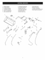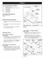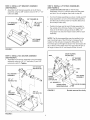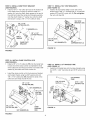
1
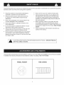
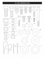
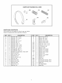
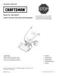
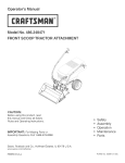
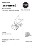
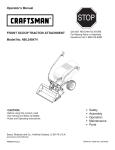
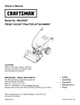
Operator's Manual
CRAFr. MAN®
FRONT SCOOP TRACTOR ATTACHMENT
DO NOT RETURN
TO STORE
For Missing Parts or Assembly
Questions Call 1-866-576-8388
Model No. 486.248474
,,
,,
,,
,,
,,
CAUTION:
Before using this product, read
this manual and follow all Safety
Rules and Operating Instructions.
Sears, Roebuck
and Co., Hoffman
Safety
Assembly
Operation
Maintenance
Parts
Estates, IL 60179 U.S.A.
www.sears.com/craftsman
PRINTED IN U.S.A.
FORM
NO. 42086
(02/02/09)
WARRANTY ....................................................................
2
SAFETY RULES ..............................................................
3
FULL SIZE HARDWARE CHART .................................... 4
CARTON CONTENTS .....................................................
6
ASSEMBLY ......................................................................
7
OPERATION ..................................................................
17
MAINTENANCE ............................................................
18
TROUBLESHOOTING ...................................................
19
REPAIR PARTS ILLUSTRATION .................................. 20
REPAIR PARTS LIST .....................................................
21
SLOPE GUIDE ..............................................................
23
PARTS ORDERING/SERVICE ......................... Back Page
ONE YEAR FULL WARRANTY
When operated and maintained according to the instructions supplied with it, if this Front Scoop Tractor Attachment fails
due to a defect in material or workmanship within one year from the date of purchase, call 1-800-4-MY-HOME® to arrange
for free repair (or replacement if repair proves impossible).
If this product is used for commercial or rental purposes, this warranty applies for only 90 days from the date of purchase.
This warranty gives you specific legal rights, and you may also have other rights which vary from state to state.
Sears, Roebuck
and Co., D817WA, Hoffman Estates, IL 60179
The model number and serial number will be found on a
decal attached to the bucket.
You should record both the serial number and the date of
purchase and keep in a safe place for future reference.
MODEL NUMBER:
SERIAL NUMBER:
DATE OF PURCHASE:
486.248474
Anypowerequipment
cancauseinjuryifoperated
improperly
oriftheuserdoesnotunderstand
howtooperatetheequipment.
Exercisecautionatalltimeswhenusingpowerequipment.
o Readthisoperator'smanualbeforeattempting
to
assemble
or operatethescoopattachment.
o Readthevehicleowner'smanualandknowhow
tooperateyourvehiclebeforeusingthescoop
attachment.
o Nevercarrypassengers
inthescoopbucket.Ithas
notbeendesignedtocarrypassengers.
o Neverallowchildrentooperatethevehicleorthe
scoopattachment.
o Donotallowadultstooperatethevehicleor scoop
attachment
withoutproperinstructions.
o Alwaysbeginwiththetransmission
infirst(low)and
graduallyincreasespeedasconditions
permit.
o Drivethetractoratreducedspeedoverroughterrain
andhillsidesor nearcreeksandditchestoprevent
tippingoverandlossofcontrol.Donotdrivetooclose
toa creekor ditch.
[_
o Neverramthescoopintomaterialat highspeed.
o Vehiclebrakingandstabilitymaybeaffectedwith
theattachment
ofthisscoop.Donotfillthescoop
to maximum
weightcapacitywithoutcheckingthe
capabilityofthevehicletosafelydriveandstopwith
thescoopattached.
o Beforeoperating
vehicleonanygrade(hill)refer
tothesafetyrulesinthevehicleowner'smanual
concerning
safeoperationonslopes.Referalsotothe
slopeguideonpage23ofthismanual.Stayoff steep
slopes!
o Followmaintenance
andlubricationinstructions
as
outlinedinthismanual.
alert!!
ookforthissymbol
Your safety is
topoint
involved.
outimportant
safetyprecautions.
Itmeans--Attention!! Become
These and other accessories are recommended for use with your unit. Call 1-800-4-MY-HOME® to find out if they are available.
If available, they may be purchased at most Craftsman outlets or by calling 1-800-4-MY-HOME®.
WHEEL
WEIGHT
TIRE CHAINS
"-i3
3
______-------
E _
._____-------
jG
F
/
/
/
F
/
/
/
/
I
i
i
/
/
I
/
/
/
/
i
/
.______-----/
____.____..-----
IV]
DD
EE
GG
HH
P
jQ
JJ
R
KK
/BB
Z
AA
CC
LL
PARTS NOT SHOWN
FULL SIZE
[ViM
QQ
RR
PP
PARTS BAG CONTENTS
Not all parts will be needed for fit-up to any one tractor.
Discard unneeded parts after assembly is finished.
REF
A
B
C
D
E
F
G
H
I
J
K
L
M
N
O
P
Q
R
S
T
U
V
QTY
2
2
3
2
6
4
5
1
3
8
2
1
2
1
2
2
2
10
11
2
3
1
DESCRIPTION
Hex
Hex
Hex
Hex
Hex
Hex
Hex
Hex
Hex
Bolt,
Bolt,
Bolt,
Bolt,
Bolt,
Bolt,
Bolt,
Bolt,
Bolt,
5/8" x 1-1/2"
1/2" x 1-3/4"
1/2" x 1"
3/8" x 1-1/4"
3/8" x 1"
5/16" x 1"
5/16" x 1-3/4"
5/16" x 3-1/2"
1/4" x 1-3/4"
Carriage Bolt, 3/8" x 1"
Carriage Bolt, 5/16"x 1"
Slotted Truss Head Bolt, 10-32 x 5/8"
Nylock Nut, 5/8"
Hex Lock Nut, 1/2"
Nylock Nut, 1/2"
Nylock Jam Nut, 1/2"
Hex Nut, 3/8"
Nylock Nut, 3/8"
Nylock Nut, 5/16"
Hex Nut, 5/16"
Nylock Nut, 1/4"
Hex Nut, 1/4"
REF
W
X
Y
Z
AA
BB
CC
DD
EE
FF
GG
HH
II
JJ
KK
LL
MM
NN
OO
PP
QQ
RR
QTY
1
2
4
3
4
6
2
6
8
8
3
2
6
8
2
2
2
1
1
6
2
1
DESCRIPTION
Nylock Nut, #10-32
Spacer, 5/8" Long
Spacer, 1/2" Long
Hairpin Cotter, Long
Hairpin Cotter, Short
Cotter Pin, 1/8" x 1-1/4"
Cotter Pin, 1/8" x 1-1/2"
Lock Washer, 3/8"
Washer, 5/16"
Washer,
Washer,
Washer,
Washer,
3/8" (Small)
1/2" (Small)
3/8" (Large)
5/8"
Washer, 1/2" (Large)
Washer, 3/4"
Washer, 1"
Clevis Pin
Compression Spring, Short
Compression Spring, Long
Cable Tie
Tilt Stop Bracket
Hose Clip
1.
2.
3.
4.
5.
6.
7.
BucketAssembly
PinStopBracket
LiftFrameAssembly
LiftBracketAssembly
TiltAnchorAssembly
Right(Long)SidePlate
Left(Long)SidePlate
8. Right(Short)SidePlate
9. Left(Short)SidePlate
10.DumpControlRod
11.LiftStrapAssembly
(2)
12.TiltBracketAssembly
13.AttachmentRod
14.DumpHandleTube
15.LiftHandleTube
16.DumpControlPin
17.DumpPivotBracket
18.DumpHandleTubeExtension
19.LiftHandleTubeExtension
19
16
TOOLS
(!)
(2)
(2)
(2)
(2)
(2)
(1)
REQUIRED
FOR ASSEMBLY
Standard Screwdriver
15/16" Wrenches (one should be box-end)
3/4" Wrenches
9/16" Wrenches
1/2" Wrenches
7/16" Wrenches
3/8" Wrench
ADDITIONAL
5/16" WASHERS
(EE)
ITEMS NEEDED
Ruler or Tape Measure
Grease
REMOVE
•
PARTS FROM CARTON
Remove the hardware pack and all loose parts from
the carton.
Lay cardboard on floor to help prevent scratching of
painted parts.
Lay out and identify all the parts and hardware as
shown on pages 4 through 6.
ASSEMBLE
SCOOP
STEP 1 : iNSTALL TWO BOLTS
(SEE FIGURE 1)
• Assemble two 3/8" x 1-1/4" hex bolts (D) and 3/8" hex
nuts (Q), threading the nut all the way onto the bolt
until it is tight against the head of the bolt.
Install a nut/bolt assembly into the bucket assembly
and fasten using a 3/8" nylock nut (R). Tighten.
Repeat for the other side.
5/16"
NYLOCK
NUT (T)
3/8" x 1=1/4"
HEX BOLT (D)
/-
3/8" NYLOCK NUT (R)
3/8" HEX NUT (e)
FIGURE 1
STEP 3: INSTALL LiFT FRAME ASSEMBLY
(SEE FIGURE 2)
• Apply grease to the mounting surface of the bucket
assembly and the inside of the lift frame arms.
Assemble the lift frame assembly to the bucket
assembly using two 5/8" x 1-1/2" hex bolts (A) and
5/8" nylock nuts (M). Tighten, then loosen the nuts
1/4 turn, or until the lift frame pivots freely.
5/8" x 1=1/2"
HEX BOLT (A)
APPLY
GREASE
APPLY
GREASE
LIFT FRAME
ASSEMBLY
/-
STEP 2: iNSTALL PiN STOP BRACKET
(SEE FIGURE 1)
• Install the pin stop bracket to the top of the bucket
assembly using four 5/16" x 1" hex bolts (F), eight
5/16" washers (EE) and four 5/16" nylock nuts (T).
Leave the bolts loose enough that the position of the
pin stop bracket can be adjusted later.
-/
5/8" NYLOCK
NUTS (M)
FIGURE 2
APPLY GREASE
5/8" x 1=1/2"
HEX BOLT (A)
STEP4:
iNSTALL LiFT BRACKET ASSEMBLY
(SEE FIGURE 3)
o
Assemble the lift bracket assembly to the lift frame
assembly using two 5/8" washers (11)and 1/8" x 1-1/4"
cotter pins (BB).
!-...
5/8" WASHER ill)
LiFT BRACKET
ASSEMBLY
1/8" x 1=1/4"
COTTER
(BB)
I'-.. ] ]
I
"4
I
I
I
LiFT FRAME
ASSEMBLY
FIGURE
STEP 6: iNSTALL LIFT STRAP ASSEMBLIES
(SEE FIGURE 5)
• Loosen the bolts and nuts on the lift strap
assemblies 1/4 turn or until the straps will slide back
and forth.You will retighten them later in step 26.
Turn the lift strap assemblies as shown. Install each lift
strap assembly to an arm of the lift bracket assembly
and then secure with a small 1/2" washer (GG) and a
short hairpin cotter (AA).
Position the lower end of each lift strap assembly to
the outside of the lift frame. Fasten to the upper front
holes in the lift frame using a clevis pin (MM), 1/2"
long spacer (Y) and short hairpin cotter (AA) for each
assembly.
NOTE: The lift strap assemblies may be installed in the
rear mounting holes of the lift frame to increase the lift
height, but this will also increase the lifting effort. The
front holes give a lift height of about 6-1/2" and require 28
Ibs. of force to lift a 150 Ib load. The rear holes will give a
lift height of about 8-1/2" and require 35 Ibs. of force.
3
STEP 5: INSTALL TILT ANCHOR ASSEMBLY
SHORT HAiRPiN
COTTER (AA)
ARM
(SEE FIGURE 4)
• Assemble the tilt anchor assembly to the lift bracket
assembly using two 1/2" x 1" hex bolts (C) and 1/2"
nylock jam nuts (P). Tighten.
/
1/2" WASHER
_P_@../
(SMALL) (GG)
1/2" NYLOCK
JAM NUTS (P)
P"_
TiLT ANCHOR _-__
1/2" x 1"
HEX BOLT
LiFT STRAP
ASSEMBLY
SHORT
HAiRPiN
(C)
/ -...
COTTER (AA)
"I
I
I
"'_)
112" SPACER (Y)
X
UPPER FRONT
MOUNTING HOLE
\
LiFT
BRACKET
FIGURE 4
CLEVIS PiN (MM)
I
I
I
1/2" x 1"
HEX BOLT (C)
\
FIGURE 5
Bucket removed for clarity
STEP7:
iNSTALL EXTENSION SPRING
STEP 8: iNSTALL STOP BRACKET
(SEE FIGURE 6)
* Lightly apply grease to the end of the arm on the tilt
anchor assembly and install the tilt bracket assembly
to the arm using a 1/2" x 1" hex bolt (C) and 1/2" hex
lock nut (N). Tighten then loosen the nut 1/4 turn, or
until the tilt bracket assembly pivots freely.
Install a 1/4" x 1-3/4" hex bolt (I) through the end of
the extension spring on the tilt bracket assembly and
then install a 1/4" hex nut (V) onto the bolt. Next,
insert the end of the bolt into the hole in the arm of
the tilt anchor assembly and install a 1/4" nylock nut
(U) onto the bolt. Tighten the nuts to secure the bolt
to the arm.
_1/4"
BOLT
(SEE FIGURE 7A)
For lift straps installed in front holes
*
Install the long compression spring (OO) and then the
two 5/8" spacers (X) onto the 5/16" x 3-1/2" hex bolt (H).
Insert the bolt into the stop bracket and install two 5/16"
hex nuts (T) onto the bolt. Adjust nuts later in step 29.
5116"HEX NUTS (T) j
_
5/8" SPACERS (X) "_
LONG COMPRESSION
SPRING (OO)
5/16" x 3-1/2"
HEX BOLT (H) I._
NYLOCK NUT (U)
Jj
1/4" REX NUT (V)
"-yJj
114"x 1-314"
HEX BOLT (I)
SPRING
FIGURE 7A
(SEE FIGURE 7B)
For lift straps installed in rear holes
* Install the long compression spring (OO) and then a 5/8"
spacer (X) onto the 5/16" x 3-1/2" hex bolt (H). Insert
the bolt into the stop bracket and install a 5/8" spacer
(X) and two 5/16" hex nuts (T) onto the bolt. Adjust nuts
later in step 29.
112" x 1" HEX BOLT (C)
5116"HEX NUTS (T) /
FIGURE 6
_
5/8" SPACERS (X) '_
LONG COMPRESSION
SPRING (OO)
5/16" x 3-1/2"
HEX BOLT (H) I._
FIGURE 7B
STEP 9: iNSTALL DUMP PIVOT BRACKET
STEP 11 : INSTALL TILT STOP BRACKETS
(SEE FIGURE 8)
• Install a 1/8" x 1-1/2" cotter pin (CC) to the inside hole
in the shaft shown in figure 8, and then install a 1"
washer (LL) onto the shaft. Apply grease to the end of
the shaft and install the dump pivot bracket assembly
onto the shaft. Install a 1" washer (LL) onto the shaft
and secure it using a 1/8" x 1-1/2" cotter pin (CC).
(SEE FIGURE 10)
•
Install a tilt stop bracket (QQ) to each side of the
bucket using a 3/8" x 1" carriage bolt (J), a small 3/8"
washer (FF) and 3/8" nylock nut (R). Do not tighten
the nuts until step 28.
TiLT STOP
BRACKET (QQ)
1/8" x 1=1/2"
COTTER PIN (CC)
\
j_'_
1" WASHERS (LL)
1/8" x 1=1/2"
COTTER PIN (CC)
/
3/8" NYLOCK
NUT (R)
DUMP PIVOT
BRACKET
_'_'-_
3/8" x 1" j_o
3/8" WASHER (FF)
CARRIAGE BOLT (J)
FIGURE 10
FIGURE 8
STEP 10: iNSTALL DUMP CONTROL ROD
(SEE FIGURE 9)
• install a 1/8" x 1=1/4" cotter pin (BB) into the inside hole
in each end of the dump control rod. Spread the ends
of the cotter pins and wrap around the rod. Install a 5/8"
washer (11)onto each end of the control rod.
STEP 12: INSTALL LiFT HANDLETUBE
(SEE FIGURE 11)
•
Install the lift handle tube into the index bracket using
two 5/16" x 1-3/4" hex bolts (G) and 5/16" nylock nuts
(s).
Install the dump control rod to the dump pivot bracket
and bucket. Fasten using two 5/8" washers (11)and
1/8" x 1-1/4" cotter pins (BB). Spread the ends of the
cotter pins and wrap around the rod.
LiFT HANDLE
TUBE
5/16" NYLOCK
1/8" x 14/4"
COTTER PiN (BB)
5/16" × 1=3/4"
HEX BOLT (G)
NUTS (S) _\®_
5/8" WASHERS (ll)
iNDEX
BRACKET
1/8" x 1=1/4"
COTTER
PINS (BB)
1/8" x 14/4"
COTTER PiN (BB)
5/8" WASHERS (ll)
DUMP
CONTROL
ROD
FIGURE 11
FIGURE 9
lO
STEP 13: INSTALL LIFT HANDLETUBE
EXTENSION
STEP 15: iNSTALL DUMP HANDLETUBE
(SEE FIGURE 12)
* Install the lift handle tube extension on the lift handle
(SEE FIGURE 14)
•
Install the dump handle tube to the dump pivot bracket
assembly using three 5/16" x 1-3/4" hex bolts (G) and
5/16" nylock nuts (S).
tube using a 1/4" x 1-3/4" hex bolt (I) and 1/4" nylock
nut (U).
LiFT HANDLE
TUBE EXTENSION
1/4" x 1=3/4"
HEX BOLT (I)
LiFT HANDLE
DUMP PIVOT
BRACKET
5/16"
NYLOCK
\
NUT(S)
/
1/4" NYLOCKNUT(U)--
XX
\
5/16"
FIGURE 12
NUTS(S)
STEP 14: INSTALL LiFT CABLE
5/16"
(SEE FIGURE 13)
* Connect the hooked end of the lift cable into the index
HEX BOLTS (G)
rod, and install the threaded cable adjuster into the
notch in the top of the index bracket, placing a nut on
each side of the notch.
FIGURE 14
Adjust the cable adjustment nuts so that when the lift
trigger is squeezed, the bottom of the index rod raises
enough to release from the latched position. The index
rod should also lower far enough to lock in the latched
position when the trigger is released.
•
x 1 =3/4"
STEP 16: INSTALL DUMP HANDLETUBE
EXTENSION
(SEE FIGURE 15)
* Install the dump handle tube extension on the dump
handle tube using a 1/4" x 1-3/4" hex bolt (I) and 1/4"
nylock nut (U).
Attach the lift cable to the lift handle using three cable
ties (PP).
Attach the dump cable to the dump handle tube using
three cable ties (PP).
LIFTTRiGGER
DUMP HANDLE
TUBE EXTENSION
\
1/4" x 1=3/4"
HEX BOLT (I)
LiFT CABLE
\
CABLE
NUTS
USETHiS HOLE
\
DUMP CABLE
1/4" NYLOCK
NUT (U)
iNDEX ROD
DUMP HANDLE TUBE
FIGURE 13
FIGURE 15
11
STEP 17: INSTALL DUMP CONTROL PiN
STEP 18: INSTALL HOSE CLiP AND SPACER
(SEE FIGURE 16)
* install a small 1/2" washer (GG) and then the short
compression spring (NN) onto the dump control pin.
install the dump control pin into the pin stop bracket.
Make sure the fiat side of the pin faces to the front
when finished.
(SEE FIGURE 17)
* Secure the dump cable to the back of the bucket
using a hose clip (RR), a #10 x 5/8" truss-head bolt
(L) and a #10-32 nylock nut (W).
Connect the hooked end of the dump cable into the
hole in the dump control pin. install the threaded cable
adjuster down into the notch in the pin stop bracket,
placing a nut on each side of the notch. Adjust and
tighten the adjuster nuts so that the tapered end of
the dump control pin extends 3/4" through the side of
the pin stop bracket.
#10=32NYLOCK
NUT (W)
/
a..
DUMP CONTROL PIN
HOSE
CLIP (RR)
#10 x 5/8"
TRUSS
HEAD BOLT(L)
PIN STOP
BRACKET
FIGURE 17
/
INSTALL
FRONT SCOOP ON TRACTOR
STEP 19: IDENTIFY YOUR TRACTOR TYPE
(SEE FIGURE 18)
*
Look underneath the front axle of your tractor. If there
is a single mower deck suspension bracket located
under the middle of the front axle, continue on to
step 20. If your tractor does not have a mower deck
suspension bracket underneath the middle of the
front axle, skip to step 22 on page 13 or step 24 on
page 14 for tractors with dual suspension brackets.
PIN STOP
BRACKET
FIGURE 16
f
MOWER DECK
SUSPENSION
BRACKET
FIGURE 18
12
STEP 21: iNSTALL FRAME BRACE
LAWN TRACTORS AND GARDEN TRACTORS
WITH SINGLE SUSPENSION
BRACKETS
(SEE FIGURE 20)
•
Install the frame brace to the inside of the side plates
using two 1/2" x 1-3/4" bolts (B), large 1/2" washers
(JJ), 1/2" spacers (Y) and 1/2" nylock nuts (O).
Install the brace in the bottom holes for Garden (GT)
Tractors and the second from bottom holes for Lawn
(LT) Tractors. Do not tighten yet.
STEP 20: iNSTALL SiDE PLATES
(SEE FIGURE 19)
• Remove any bolts present in the mounting holes on
the left side of the tractor frame. Do not remove bolts
from right side of frame until left side plate has been
installed.
Install the left (long) side plate on the tractor frame
using three 3/8" x 1" carriage bolts (J), three 3/8"
nylock nuts (R), one 5/16"x 1" carriage bolt (K), one
5/16" nylock nut (S) and three large 1/2" washers (JJ)
if needed (see note). Do not tighten yet. Repeat for
the right (long) side plate.
NOTE: If an engine mounting plate is present
dotted lines) that prevents the side plate from
against the tractor frame, place 1/2" washers
front two 3/8" bolts and on the rear 5/16" bolt
•
Tighten all nuts on side plates and frame brace.
•
Skip to step 25 on page 15.
1/2" x 1=3/4"
HEX BOLT (B)
1/2" LARGE
(shown with
resting flat
(11)on the
to serve as
WASHER (JJ)
shims between the side plate and the frame.
5/16" x 1"
(3) 3/8" x 1"
CARRIAGE BOLTS (J)
CARRIAGE BOLT (K)
ENGINE
MOUNTING
5/16"
PLATE
1/2" SPACER
(Y)
FOR LT
NYLOCK
NUT (s)
1/2" NYLOGK
NUT (O)
HOLE FOR GT
FRAME BRACE
FIGURE 20
(SEE NOTE)
LEFT (LONG)
SiDE PLATE
(3) 3/8" NYLOCK
NUTS(R)
FIGURE 19
13
LAWN TRACTORS
BRACKETS
WiTH DUAL SUSPENSION
GARDEN TRACTORS WiTH DUAL
SUSPENSION
BRACKETS
STEP 22: iNSTALL SIDE PLATES
STEP 24: iNSTALL SIDE PLATES
(SEE FIGURE 21)
• Remove any bolts present in the mounting holes on
the left side of the tractor frame. Do not remove bolts
(SEE FIGURE 23)
•
Remove any bolts present in the mounting holes on
the left side of the tractor frame. Do not remove bolts
from right side of frame until left side plate has been
installed.
from right side of frame until done with left side plate.
Fasten the left (long) side plate to the tractor frame
using three 3/8" x 1" hex bolts (E), 3/8" small washers
(FF), and 3/8" lock washers (DD). If there is a bracket
like the one shown with dotted lines, use a 3/8" large
washer (HH) as a shim on the rear bolt. Do not
tighten yet. Repeat for the right (long) side plate.
Install the left (short) side plate with the pin to the
outside using two 3/8" x 1" hex bolts (E) and 3/8" lock
washers (DD). Tighten only until bolts are snug and
lock washers are flattened. Repeat for the right side
plate.
3/8" LARGE
WASHER (HH)
(if
:led)
(3) 3/8" SMALL
WASHERS (FF)
Install a 3/4" washer (KK) and a long hairpin cotter
(Z) to the pin in each side plate. Remove them while
mounting the scoop.
LEFT (GT)
SiDE PLATE
(3) 3/8" × 1"
HEX BOLTS (E)
(3) 3/8" LOCK
WASHERS (DD)
FIGURE 21
d_L_-..@
STEP 23: iNSTALL FRAME BRACE
(SEE FIGURE 22)
• Install the frame brace between the side plates using
two 1/2" x 1-3/4" bolts (B), large 1/2" large washers
(JJ), 1/2" spacers (Y) and 1/2" nylock nuts (O). Use the
second hole from the bottom in the plates. Tighten.
/
_
LONG
HAIRPIN
3/4" WASHER (KK)
COTTE R (Z)
FIGURE
•
Tighten 3/8" x 1" hex bolts (E) in side plates only until
they are snug and the lock washers are flattened.
•
Skip to step 25 on page 15.
1/2" x 1-3/4"
v
HEX BOLT (B)
_ 1/2" SPACER(Y)
/
1/2" LARGE
WASHER (JJ)
1/2" NYLOCK
0.. "%
NUT (O)
FRAME BRACE
FIGURE 22
14
23
_WASHERS
(DD)
(2) 3/8" x 1"
HEX BOLTS(E)
INSTRUCTIONS
STEP 26: ADJUSTTILT
FOR ALL TRACTORS
AND PIN STOP BRACKETS
(SEE FIGURE 25)
• Lower the scoop assembly onto a smooth level surface.
For normal use, let the bottom of the bucket rest flat on
the ground. For more aggressive scraping action, place
1/4" shims under the rear of the bucket at each end.
STEP 25: MOUNT SCOOPTOTRACTOR
(SEE FIGURE 24)
• Align the scoop with the side plates on the front of the
tractor. Lift the rear of the scoop and slide the notches
in the scoop frame onto the bolts or pins in the tractor
side plates. Stand on the left side of the tractor and
push down on the scoop dump handle until the holes
in the scoop frame and the holes in the side plates are
aligned. Install the attachment rod through the holes
from the left side and secure it with a long hairpin
cotter (Z).
Make sure the two smaller bolts in the tilt bracket
and the four bolts in the pin stop bracket are slightly
loosened.
Swing the tilt bracket forward and position the pin stop
bracket so the end of the dump control pin inserts into
the hole in the tilt bracket.
Adjust the pin stop bracket so that it is flush and square
with the front of the bucket. Leave a small gap between
the side of the pin stop bracket and the tilt bracket. The
taper on the end of the dump control pin should now
extend all the way through the tilt bracket. TIGHTEN the
bolts and nuts in the pin stop bracket
DUMP HANDLE
LONG
HAIRPIN
COTTER (Z)
TIGHTEN the two bolts and nuts in the tilt bracket.
DUMP
CONTROL PIN
BOLT OR PiN
ATTACHMENT
ROD
-%
SCOOP
ASSEMBLY
FIGURE 24
SMALLER
BOLTS
TILT BRACKET
PIN STOP BRACKET
FIGURE 25
15
STEP 27: ADJUST LIFT STRAPS
STEP 29: ADJUST STOP BOLT
(SEE FIGURE 26)
* Make sure the nuts and bolts in the lift straps are
loose enough to turn by hand. Stand beside the right
side of the scoop and hold the lift handle as far
forward as it will go until you tighten one of the nuts
in the lift straps. Let go of the lift handle and tighten
the other three nuts in the lift straps.
(SEE FIGURE 28)
* Keep the scoop locked in the TRANSPORT position.
Adjust the nuts on the stop bolt in or out until the
dump control pin is centered in the slot of the tilt
bracket when the tilt bracket is pulled back against the
stop bolt. Securely tighten the two nuts together.
/
LIFT
NOTE: If the lift strap assemblies are moved to the rear
mounting holes, one of the spacers on the stop bolt
will need to be moved to the back side of the bolt stop
bracket. Refer to step 8 on page 9.
HANDLE
BOLT
TIGHTEN
BOLT
DUMP CONTROL
PIN
TILT BRACKET
TIGHTEN
NUTS
FIGURE
LIFT STRAP
ASSEMBLIES
FIGURE 28
26
STEP 30: CHECK DUMPING OPERATION
•
STEP 28: ADJUST TILT STOP BRACKETS
(SEE FIGURE 27)
* Raise the scoop until it locks in the TRANSPORT
position. Push the tilt stop brackets (QQ) on each side
of the bucket down against the lift frame arms, and
tighten the nuts.
NOTE: Readjust the tilt stop brackets if you move the lift
strap assemblies from the front to rear holes or from
the rear to front holes. Refer to step 6 on page 8.
TILT STOP
BRACKET
(QQ)
LIFT FRAME ARM
FIGURE 27
16
With the scoop in the transport position, squeeze the
dump trigger and push down on the dump handle
to dump the bucket. Release the dump trigger and
lift up on the handle to lock the bucket in the upright
position. If the dump control pin does not lock into the
tilt bracket, loosen the bolts tightened in steps 26, 27
and 28 and then repeat steps 26, 27 28 and 29.
KNOWYOUR
FRONT END SCOOP
Always test to make sure your vehicle has adequate
power and braking capabilities whenever hauling a
substantial amount of weight in your front end scoop.
Use extra caution when operating on slopes.
Read this owner's manual and safety rules before
operating your front end scoop.
Compare the illustration below with your front end scoop
to familiarize yourself with the various controls and their
locations.
•
For best handling and traction, distribute the weight of
the load evenly in the bucket.
LIFT
HANDLE
CAUTION:
MATERIAL NEVER
AT HIGHRAMTHE
SPEEDS.SCOOP INTO
DUMP
HANDLE
L IFT
TRIGGER
LEVER
Keep the lift handle locked in the raised position when
tilting the scoop bucket forward to dump.
/
The lift handle must be locked in the raised position to
allow the dump handle to lock the scoop bucket back
in the upright position after dumping.
DUMP
TRIGGER
LEVER
Do not scrape or push material with the scoop bucket
while it is tilted forward.
Add wheel weights for improved traction when using
the scoop.
To dump material from the bucket, squeeze the dump
trigger and push the dump tube handle down. Release
the trigger before returning the bucket to the upright
position.
DUMP TRIGGER LEVER Press to release the dump pin.
DUMP HANDLE Press down to dump the bucket.
LIFTTRIGGER LEVER Press to release the index pin.
LIFT HANDLE Press down to lift the bucket assembly.
To lower the bucket, squeeze the lift trigger and
then lift up on the lift handle. If the trigger is hard
to depress, you may need to push down on the lift
handle while squeezing, and then lift up. Release
the trigger before retuning the bucket to the raised
position.
HOW TO USE YOUR SCOOP
DO NOT EXCEED 200 LB. CAPACITY OF BUCKET
One cubic foot of dirt weighs approximately 80 Ibs.
One cubic foot of dry sand or gravel weighs
approximately 100 Ibs.
&
CAUTION: VEHICLE BRAKING
STABILITY MAY BE AFFECTED
ADDITION OF AN ACCESSORY
ATTACHMENT. BE AWARE OF
CONDITIONS ON SLOPES.
Do not exceed mowing speed (3 mph) when the front
end scoop is attached to the tractor.
AND
WITH THE
OR AN
CHANGING
Refer to the vehicle owner's manual for instructions on
safe operation on slopes.
Use the slope guide provided on page 23 of this manual
to determine whether slope angle is too steep for safe
operation.
17
&
CAUTION: TO AVOID POSSIBLE INJURY,
MAKE SURE THAT NO ONE IS NEAR
THE BUCKET BEFORE DUMPING THE
BUCKET.
&
CAUTION: ALWAYS LOWER THE SCOOP
BUCKET TO THE GROUND BEFORE
LEAVING THE TRACTOR.
CUSTOMER
•
RESPONSiBiLiTiES
Read and follow the maintenance schedule and the maintenance procedures listed in this section.
MAINTENANCE
SCHEDULE
Fill in dates as you
complete regular service.
Check for loose fasteners
__/_,_y
__4
'/"
Service Dates
X
Cleaning
Lubrication
CHECK
e_
!,,,i_,_7_zC,_z_/"
X
X
FOR LOOSE FASTENERS
LUBRICATION
Before each use make a thorough visual check of
the front end scoop for any bolts and nuts which may
have loosened. Retighten any loose bolts and nuts.
Lightly oil all pivot points on the scoop lift mechanism.
Lightly oil the surface on the scoop bucket where the
attachment lift frame pivots.
Apply a good grade of spray lubricant to the trigger
assemblies on the lift handle and dump handle.
CLEANING
After each use, clean off any dirt and debris from the
scoop bucket lift frame.
Before storing at the end of each season, rinse off
the scoop bucket and scoop lift frame. Allow to dry
thoroughly. Paint any exposed metal surfaces to
protect from rust.
Store in a clean, dry area.
18
PROBLEM
CAUSE
CORRECTION
Scoop won't lock into
raised/transport position.
1. Index rod is jamming.
2. Frame is hitting tilt stop
brackets.
1. Apply grease to the bottom slot in the
lift bracket, where the index rod slides
2. Adjust the tilt stop brackets as
instructed on page 16.
1. Dump control pin does not align
with the tilt bracket.
1. Adjust the tilt bracket and lift straps as
instructed on page 16.
Scoop bucket won't lock into level
position after dumping.
2. Adjust the stop bolt as instructed on
page 16.
Lift handle trigger won't release
scoop from the transport position.
1. Index rod is jamming.
2. Lift cable is not adjusted properly.
1. Apply grease to the bottom slot in the
lift bracket, where the index rod slides.
2. Adjust cable nuts as instructed on page
11.
Dump handle trigger won't
release bucket to dump.
1. Dump control cable is not adjusted
properly.
2. Pin stop bracket is not adjusted
properly side to side.
1. Adjust parts as instructed in step 17 on
page 12.
2. Adjust parts as instructed in step 26 on
page 15.
Bucket is becoming more difficult
to tilt up or down.
1. Debris is lodged between bucket
assembly and lift frame.
1. Remove all debris from between the
bucket assembly and the lift frame.
19
REPAIR PARTS FOR MODEL 486.248474
36
/
37
79
15
71
22
69
/
13
/
/
/
30
31 3!
29
67
\l
14
J
/
\
78
4
\
33
38
/
5
/
/
/
/
\
/
77
lO
\
39
\
\
I
I
\
)
19
43
I
I
41
I 26
52
13
/
43
53
42
13
51
52
51
/
5245
52
|
/
/
54
/
59 6
/
61
\
/
/
/
64
/
/
63
/
/
/
/
/
/
/
13
52
45
62
2O
45
45
REPAIR PARTS FOR MODEL 486.248474
REF
1
2
3
4
5
6
7
8
9
10
11
12
13
14
15
16
17
18
19
20
21
22
23
24
25
26
27
28
29
30
31
32
33
34
35
36
37
38
39
40
41
42
PART NO.
1509-69
726-0178
49265
49266
47674
47025
43009
23658
49912
47189
47369
47368
47810
HA21362
43070
25350
43063
25343
741-0192
R19171616
43055
43001
732-0306
43262
66258
48115
63675
25510
43343
R74780828
R19172410
24817
712-3083
43003
712-0261
63568
63569
49270
47066
49271
40173
43601
QTY
3
6
1
2
2
1
2
2
1
3
1
1
14
14
14
4
7
1
2
4
4
10
2
1
1
2
1
2
3
2
8
4
2
6
2
1
1
1
1
1
1
3
DESCRIPTION
REF
Hex Bolt, 1/4-20 x 1-3/4" (Grade 5)
Cable Tie
Lift Handle Extension
43
44
45
Oval Screw, 10-24 x 1-1/2"
Plastic Plug, 1-1/4" O.D. Tube
Hex Bolt, 5/16-18 x 3-1/2" (Gr. 5)
Flat Washer, 3/4"
Spacer, .39" x .56"x .62" L
Cable, Lift
Nylock Nut, 1/4"
Roll Pin, 3/16" x 1-3/4"
Roll Pin, 5/16" x 1-3/4"
46
47
48
49
50
51
52
53
54
Nylock Nut, 5/16-18
Nylock Nut, 3/8-16
Flat Washer, 3/8"
55
56
57
Lift Strap
Hex Bolt, 5/16-18 x 1" (Grade 5)
Lift Bracket
58
59
60
Flange Bearing with Flats
Flat Washer, 1/2" x 1" (Small)
Hairpin Cotter, 3/32" x 1.8"
61
62
63
Hex Bolt, 3/8-16 x 1" (Grade 5)
Spring, Compression
Hex Lock Nut, 1/2-13
Tilt Anchor Assembly
Nylock Jam Nut, 1/2-13
Lift Arm Assembly
Mounting Bracket
Hairpin Cotter, 3/32" x 2-5/16"
Hex Bolt 1/2-13 x 1-3/4" (Grade 5)
Flat Washer, 1/2"x 1-1/2" (Large)
Spacer, 0.52" x 0.75" x 0.5"
Nylock Nut, 1/2-13
Lock Washer, 3/8"
64
65
66
67
68
69
70
71
72
73
74
75
76
Nylock Nut, 5/8-11
Right (Short) Side Plate
Left (Short) Side Plate
Dump Handle Tube Extension
Attachment Rod
77
78
79
80
81
Dump Handle Tube
Dump Control Cable
Washer, 1.59" x 1.032" x 0.60"
82
* Purchase Common Hardware Locally
21
PART NO.
43093
710-0865
R19212016
25852
25851
HA6441
43350
64963
43084
43010
64968
49273
49268
48905
46055
25335
47171
HA23761
43346
64962
43015
43087
47572
26481
25722
43081
44326
710-0367
736-0247
43000
44062
142
R19131316
63773
48049
49264
25562
25563
43064
43178
42086
QTY
3
3
6
1
1
1
8
1
5
6
1
1
1
1
1
1
1
1
1
1
3
3
2
2
1
8
2
2
2
1
2
1
2
1
1
1
1
1
2
1
1
DESCRIPTION
Cotter Pin, 1/8" x 1-1/2"
Hex Bolt, 1/2-13 x 1" (Grade 5)
Flat Washer, 5/8"x 1-1/4" x 16 Ga.
Tilt Bracket Extension Strap
Tilt Bracket
Hex Bolt, 3/8-16 x 2" (Grade 5)
Bolt, Carriage 3/8-16 x 1" (Grade 5)
Lift Frame Assembly
Hex Bolt, 5/16-18 x 1-3/4" (Grade 5)
Cotter Pin, 1/8" x 1-1/4"
Dump Pivot Bracket
Dump Control Rod
Dump Control Pin
Compression Spring
Spring Pin, 1/8" x 1"
Pin Stop Bracket
Nylock Nut, #10-32
Hose Clamp
Truss-Head Bolt #10-32 x 5/8"
Bucket Assembly
Hex Nut, 3/8-16
Hex Bolt, 3/8-16 x 1-1/4" (Grade 5)
Nut, Hex 3/8-16 Lock Flanged
Tilt Stop Bracket
Frame Brace
Flat Washer, 5/16"
Carriage Bolt, 5/16"x 1" (Grade 5)
Hex Bolt, 5/8-11 x 1-1/2" (Grade 5)
Washer, .41"x 1.25"x .156"
Extension Spring
Clevis Pin, 1/2"x 1"
Cotter Pin, 1/8" x 3/4"
Flat Washer, 3/8"x 13/16" x 1/16"
Index Bracket Assembly
Index Rod
Lift Handle Tube
Right (Long) Side Plate
Left (Long) Side Plate
Nut, Hex 5/16-18
Nut, Hex 1/4-20
Owner's Manual
NOTES
22
SUGGESTED GUIDE FOR SIGHTING
OF TRACTOR WITH ATTACHMENT
SLOPES FOR SAFE OPERATION
FOLD ALONG
D(
LINE
SLo
ONLY RIDE UP AND DOWN
NOT ACROSS HILL
HILL,
O3
10 DEGREES
&
MAX.
WARNING: To avoid serious injury, operate your tractor up and
down the face of slopes, never across the face. Do not operate
on slopes greater than 10 degrees. Make turns gradually to
1. Fold this page along dotted line indicated above.
2. Hold page before you so that its left edge is vertically parallel to a tree
trunk or other upright structure.
3. Sight across the fold in the direction of hill slope you want to measure.
4. Compare the angle of the fold with the slope of the hill.
Your Home
For expert troubleshooting
and home solutions
advice:
www.managemyhome.com
For repair - in your home - of all major brand appliances,
lawn and garden equipment, or heating and cooling systems,
no matter who made it, no matter who sold it!
For the replacement parts, accessories and
owner's manuals that you need to do-it-yourself.
For Sears professional installation of home appliances
and items like garage door openers and water heaters.
1-800-4-MY-HOME
Call anytime,
®
(1-800-469-4663)
day or night (U.S.A.
www.sears.com
and Canada)
www.sears.ca
Our Home
For repair of carry-in items like vacuums, lawn equipment,
and electronics, call anytime for the location of your nearest
Sears Parts & Repair Service
1-800-488-1222
(U.S.A.)
1-800-469-4663
www.sears.com
To purchase
a protection
1-800-827-6655
Para pedir servicio
a domicilio,
agreement
on a product serviced
by Sears:
1-800-361-6665
(Canada)
de reparaci6n
Au Canada
piezas:
® Marca
Mc Marque
Trademark
Registrada
/ TM Trademark
/ TM Marca
de commerce
/ SM Service
de Fabrica / SM Marca
/ MD Marque
depos6e
pour service
en fran(;ais:
1-800-LE-FOYER
1-888-S U-H OGAR ®
® Registered
(Canada)
www.sears.ca
(U.S.A.)
y para ordenar
Center
Mc
(1-800-533-6937)
Mark of Sears
de Servicio
de Sears
Brands,
Brands,
de Sears
LLC
LLC
Brands,
LLC
® Sears Brands, LLC