1
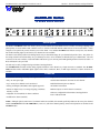
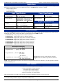
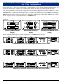
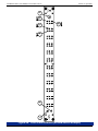
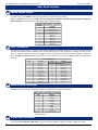
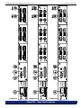
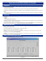
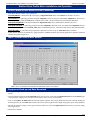
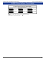
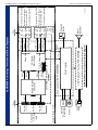
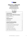
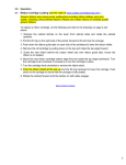
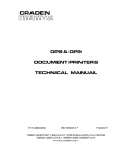
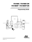
ALARM-24 Series
1U Audio Alarm Monitor
Analog or Digital Inputs, Up To 24-Channels,
Loss-of-Audio/Clipping/Phase Monitoring,
with Visual and Audible Alarm Indication
Document P/N 821542 Rev-A
User Manual
CONTENTS
Title and Contents ........................................................... 1
Introduction ............................................................................................ 2
Section 1: General Features and Specifications ....... 3
Description and Features ....................................................................... 4
Applications, Specifications, Standard Models, and Other Options ...... 5
Rear Panel Configurations ..................................................................... 6
Section 2: Operation ....................................................... 7
Installation ............................................................................................. 9
Alarm Sounder Enable/Disable Instructions .......................................... 9
Front Panel Features .............................................................................. 10
Rear Panel Features ............................................................................... 12
Alarm Profile Editor Installation and Operation .................................... 16
Section 3: Technical Information ................................. 19
RS232 Status and Control ...................................................................... 20
ALARM-24 Internal Settings - Channel Address ................................... 21
ALARM-24A (Analog) Interconnect Block Diagram ............................. 22
ALARM-24D (Digital) Interconnect Block Diagram ............................. 23
© 2003 Wohler Technologies Inc. ALL rights reserved
1
Important Safety Instructions
1)
Read these instructions.
2)
Keep these instructions.
3)
Heed all warnings.
4)
Follow all instructions.
5)
Do not use this apparatus near water.
6)
Clean only with dry cloth.
7)
Do not block any ventilation openings. Install in accordance with the manufacturer's instructions.
8)
Do not install near any heat source such as radiators, heat registers, stoves, or other apparatus (including
amplifiers) that produce heat.
9)
Do not defeat the safety purpose of the polarized or grounding-type plug. A polarized plug has two blades
with one wider than the other. A grounding type plug has two blades and a third grounding prong. The
wide blade or the third prong are provided for your safety. If the provided plug does not fit into your outlet,
consult an electrician for replacement of the obsolete outlet.
10) Protect the power cord from being walked on or pinched, particularly at plugs convenience receptacles
and the point where they exit from the apparatus.
11) Only use attachments/accessories specified by the manufacturer.
12) Use only with the cart stand, tripod, bracket, or table specified by the manufacturer, or sold with the
apparatus. When a cart is used, use caution when moving the cart/apparatus combination to avoid injury
from tip-over.
13) Unplug this apparatus during lightning storms or when unused for long periods of time.
14) Refer all servicing to qualified service personnel. Servicing is required when the apparatus has been
damaged in any way, such as when power-supply cord or plug is damaged, liquid has been spilled or
objects have fallen into the apparatus, the apparatus has been exposed to rain or moisture, does not
operate normally, or has been dropped.
15) Do not expose this apparatus to rain or moisture.
16) The apparatus shall be connected to a mains socket outlet with a protective earthing connection.
CAUTION!
In products featuring an audio amplifier and speakers, the surface at the side of the
unit, where the audio amplifier heat sink is internally attached, may get very hot after
extended operation. When operating the unit excercise caution when touching this
surface and ensure that external materials which may be adversely affected by heat
are not in contact with it. There is a Hot Surface label (see diagram) attached to the
aforementioned surface of the product.
Introduction
Congratulations on your selection of a Wohler Technologies product. We are confident it represents the best performance and value
available, and we guarantee your satisfaction with it.
If you have questions or comments you may contact us at:
Wohler Technologies, Inc.
31055 Huntwood Avenue
Hayward, CA 94544
Phone: (510) 870-0810
Fax: (510) 870-0811
US Toll-Free: 1-888-596-4537
www.wohler.com
2
[email protected]
© 2007 Wohler Technologies, Inc. ALL rights reserved
ALARM-24 Series User Manual P/N 821542 Rev-A
Section 1
General Features
and Specifications
Description
Features
Applications
Specifications
Standard Models
Other Options
© 2003
Wohler Technologies Inc. ALL rights reserved
3
ALARM-24 Series User Manual P/N 821542 Rev-A
Section 1: General Features and Specifications
ALARM-24 Series
1U Audio Alarm Monitor
1
2
3
5
4
6
7
8
9
11
10
12
13
14
15
16
17
18
19
20
21
22
23
24
POWER
CLIP
WOHLER
TECHNOLOGIES
X
Φ
X
Φ
X
Φ
X
Φ
X
Φ
Φ
X
X
Φ
X
Φ
X
Φ
X
Φ
X
Φ
X
LOSS
Φ
RESET
ALARM-24
SERIES
ALL
ALARM-24xS/x
Description
The Wohler ALARM-24 audio error alarm systems provide audible and visual alarms for loss of audio, over-range (clipping), and
phase/polarity reversal. When a fault condition occurs, it activates individual channel LEDs and sets off an acoustic alarm. It also
energizes a rear-panel relay contact closure(s) for remote alarm. The standard ALARM model features twenty-four (24) channels
but models featuring eight (8) and sixteen (16) channels are also available
The alarm is activated by audio levels falling outside of a pre-determined range for a pre-determined period of time. They allow for
the setting of both level and time delay on a per-channel pair basis. Error conditions are identified on a per-channel basis. After the
occurrence of an error condition, visual and audible indication is given via front panel LED signaling and Piezo buzzer activation. A
Reset All button is also provided.
The unit may be easily configured using a Windows based application.
The ALARM-24Ax/x models monitor analog signals and feature "mini" Phoenix stye input connectors as standard. The ALARM24Dx/x models monitor AES/EBU digital signals with a choice of Phoenix, BNC, or XLR input connectors. Custom variations are
available.
Features
• Centralized monitoring of facility-wide signal conditions
• Eight, twelve, or twenty-four channel models available
• Only one rack space high
• Visible alarm indication via LEDs for each channel
• Up to twenty-four channels can be monitored
• Individual channel pair reset buttons
• Analog and Digital (AES/EBU) audio signals supported
• All channel clear button
• Alarms for Signal Loss, Over-range (clipping), and Phase/
Polarity reversal
• Balanced inputs on "mini" Phoenix connectors
• Adjustable level thresholds for alarm conditions
• Software configurable with Windows based application
• Power indication LED
• Audible Piezo alarm (mutable)
NOTE: Although eight (8) and sixteen (16) channel models are available, this manual specifically addresses the twenty-four channel
models (ALARM-24Ax/x and ALARM-24Dx/x). However, aside from channel quantity, function and operation are identical for all
ALARM models.
4
© 2003 Wohler Technologies Inc. ALL rights reserved
ALARM-24 Series User Manual P/N 821542 Rev-A
Section 1: General Features and Specifications
Applications
The ALARM-24 audio alarm monitor units are an adaptable and effective way to monitor any analog or AES/EBU digital audio
application. The following are some of the applications where an ALARM-24 unit would prove valuable.
·
Radio Broadcast Station
·
TV Control Room
·
Remote Monitoring
Input Specifications
Power Specifications
AC mains power:
100-250 VAC, 50/60 Hz universal
input, auto switching
Power consumption:
25W
Input Sampling Rate:
32k - 48k Auto (AES)
Input Connector(s):
Analog (standard): "Mini" Phoenix (6-pin)
Digital (standard): Phoenix (3-pin)
Digital (optional): BNC or XLR (3-pin)
Digital Input Impedance:
(AES/EBU)
Phoenix: 110 Ω, balanced
XLR:
110 Ω, balanced
BNC:
75 Ω, unbalanced
Dimensions (H x W x D): 1.75 x 19 x 8 inches
45 x 483 x 203 mm
Analog Input impedance:
"Mini" Phoenix: >10K Ω, balanced
Weight:
Physical Specifications
6 lbs./2.7 kg
Standard Models
The standard ALARM model features twenty-four (24) channels, but models featuring eight (8) and sixteen (16) channels are also
available as options. Below are the model names as denominated for the ALARM-24 models.
ALARM-24AM/P:
ALARM-24AS/P:
ALARM-24DM/P:
ALARM-24DS/P:
ALARM-24DM/B:
ALARM-24DS/B:
ALARM-24DM/X:
ALARM-24DS/X:
Analog inputs, Mono, on Phoenix connectors
Analog inputs, Stereo, on Phoenix connectors
Digital (AES) inputs, Mono, on Phoenix connectors
Digital (AES) inputs, Stereo, on Phoenix connectors
Digital (AES) inputs, Mono, on BNC connectors
Digital (AES) inputs, Stereo, on BNC connectors
Digital (AES) inputs, Mono, on XLR connectors
Digital (AES) inputs, Stereo, on XLR connectors
Model Option Naming Key
1st Appended Letter.......... Signal
{ AD == Analog
Digital
2nd Appended Letter...... Monitor
Mono
{MS == Stereo
/P = Phoenix*
/B = BNC (Female)
/X = XLR (3-Pin Female)
{
3rd Appended Letter... Connector
*Analog models use 6-pin "mini" Phoenix connectors,
Digital models use standard 3-pin Phoenix connectors.
NOTE: In the model names throughout this manual, the unspecified stereo/mono is indicated by "x" and unspecified connector
option is indicated by "/x".
Other Options
Other options are available by special order including:
• Custom combinations of input connectors
• 26-segment high resolution displays
• 53-segment high resolution displays
• Eight (8) and sixteen (16) channel models
Other custom options are possible. Call your dealer or Wohler Technologies to discuss your specific needs.
Units are designed to meet, at time of manufacture, all currently applicable product safety and EMC requirements, such as those of
CE. Features and specifications subject to improvement without notice.
© 2003
Wohler Technologies Inc. ALL rights reserved
5
ALARM-24 Series User Manual P/N 821542 Rev-A
Section 1: General Features and Specifications
Rear Panel Configurations
The 1U ALARM-24 rear panels are comprised of modular panel sections. In any given ALARM-24 model, three of the modular
panel sections have the audio input connectors, with the fourth remaining section containing the alarm controller features. This
arrangement permits mixing of different types of input modules, although such mixes are considered special order items.
The following illustration shows three types of input panel section modules (two digital and one analog) available for use in the
ALARM-24 series. Analog models are referred to with an "A" appended to the standard product name and Digital (AES) models are
referred to with a "D" appended. Stereo models append an "S" after the input type and Mono models append an "M". Models featuring
Phoenix connector inputs use a "P" as the last letter of the model name. BNC connector inputs use a "B". XLR connector inputs use
an "X". See page 5 for a list of all standard models in the ALARM-24 series.
AES (110 )
TERM
TERM
CH A
AES
75
1-2
CH A
CH B
CALIB
TERM
TERM
AES
75
7-8
5-6
BNC Input Modular Section
for ALARM-24Dx/B
(Digital)
"Mini" Phoenix Input Modular Section
for ALARM-24Ax/P
(Analog)
Below are illustrations showing three standard configurations of the ALARM-24 series rear panels.
AES (110 )
AES (110 )
AES (110 )
PORT 1
INTERNAL POWER
TERM
17
18
11
12
21
22
15
16
TERM
TERM
9
10
3
4
13
14
7
8
1
2
TERM
TERM
UNDERWRITERS LABS
SEE POWER SUPPLY
LABEL ON SIDE
TERM
RS232
OPT
TERM
TERM
TERM
5
6
TERM
TERM
TERM
ALARM-24Dx/P Rear Panel (24-Channel Digital with Standard Phoenix Inputs)
19-20
17-18
TERM
TERM
AES
11-12
AES
75
75
9-10
TERM
TERM
AES
3-4
75
75
75
23-24
INTERNAL POWER
75
75
15-16
RS232
OPT
AES
AES
UNDERWRITERS LABS
SEE POWER SUPPLY
LABEL ON SIDE
75
TERM
TERM
AES
21-22
PORT 1
AES
75
TERM
TERM
AES
1-2
TERM
TERM
AES
AES
75
TERM
TERM
AES
AES
75
75
13-14
5-6
7-8
CH B
CALIB
CH A
23-24
CH A
CH A
17-18
11-12
21-22
15-16
CH B
CH A
CH B
CH B
CH A
CH A
CH B
CH A
9-10
3-4
13-14
7-8
CH B
CH B
CALIB
CH B
PORT 1
CH A
INTERNAL POWER
CH B
UNDERWRITERS LABS
SEE POWER SUPPLY
LABEL ON SIDE
1-2
CH A
CH B
CALIB
CH A
CALIB
CH B
CALIB
CH A
CALIB
ALARM-24Dx/B Rear Panel (24-Channel Digital with BNC Inputs)
19-20
OPT
CH A
RS232
CH B
5-6
ALARM-24Ax/P Rear Panel (24-Channel Analog with "mini" Phoenix Inputs)
6
CH B
TERM
Phoenix Input Modular Section
for ALARM-24Dx/P
(Digital)
23
24
CH A
AES
75
19
20
CH B
3-4
TERM
TERM
CH A
AES
75
TERM
CH B
CALIB
Note: Models configured with XLR connectors are limited to 12 channels (or less) due to space constraints when using these larger
connectors.
© 2003 Wohler Technologies Inc. ALL rights reserved
ALARM-24 Series User Manual P/N 821542 Rev-A
Section 2
Operation
Installation
Alarm Sounder Enable/Disable Instructions
Front Panel Features
Rear Panel Features
Wohler Alarm Profile Editor Installation and Operation
© 2003
Wohler Technologies Inc. ALL rights reserved
7
ALARM-24 Series User Manual P/N 821542 Rev-A
8
© 2003 Wohler Technologies Inc. ALL rights reserved
Section 2: Operation
ALARM-24 Series User Manual P/N 821542 Rev-A
Section 2: Operation
Installation
Mounting
The unit should be mounted where convenient for operating persons, ideally at approximately eye level for best visual monitoring.
Heat Dissipation
No special considerations for cooling are necessary as long as the ambient temperature inside the rack area does not exceed
approximately 40°C (104°F).
Mechanical Bracing
The chassis is securely attached to the front panel at five points along its surface, not just at the four corners of the chassis ears.
This feature will reduce or eliminate rear bracing requirements in many mobile/portable applications. The weight of internal
components is distributed fairly evenly around the unit.
Audio Connections
Connection of the audio feeds is straightforward. Please refer to the system interconnect block diagram on pages 22 and 23 for
clarification of the general signal paths into the ALARM-24 series units.
Care should be exercised to avoid mis-matched cable types and other similar causes of undesired reflections in RF signal systems.
Electrical Interference
As with any audio equipment, maximum immunity from electrical interference requires the use of shielded cable; however,
satisfactory results can sometimes be obtained without it. The internal circuitry common is connected to the chassis.
AC Power
The unit's AC mains connection is via a standard IEC inlet, with safety ground connected directly to the unit's chassis. The
universal AC input (100-240VAC, 50/60Hz) switching power supply is a self-resetting sealed type, with automatic over-voltage
and over-current shutdown. There is no user-replaceable fuse in either the primary or secondary circuit.
Alarm Sounder Enable/Disable Instructions
All ALARM-24 Series units feature a Piezo Alarm Sounder located on the front panel (Item 1, page 10). This sounder produces an
audible alarm when the configured alarm threshold has been exceeded. This sounder may be disabled or enabled using the instructions
below.
To ENABLE the acoustic sounder in the unit, perform the following steps on the front panel:
1) Hold down the Reset All button (Item 7, page 10)
2) Press and release the Channel 3 Reset Alarm button (Item 3, page 10)
3) Release the Reset All button
To DISABLE the acoustic sounder in the unit, perform the following steps on the front panel:
1) Hold down the Reset All button (Item 7, page 10)
2) Press and release the Channel 1 Reset Alarm button (Item 3, page 10)
3) Release the Reset All button
© 2003
Wohler Technologies Inc. ALL rights reserved
9
ALARM-24 Series User Manual P/N 821542 Rev-A
Section 2: Operation
Front Panel Features
Please refer to the example in Figure-2a on the following page to familiarize yourself with the front panel features of the ALARM24 Series units. The following sections describe these functions and are referenced, by number, to Figure-2a.
1
Alarm Sounder
The Piezo Alarm Sounder produces an audible alarm when the the alarm threshold has been exceeded. See page 9 for
instructions for how to disable or enable the Alarm Sounder.
2
Loss (of Audio) Indication LED
This RED LED lights up to indicate that the loss of audio alarm threshold has been exceeded in the associated channel.
3
Channel Reset Button
ALARM-24xS/x: For the stereo product, this momentary push-button resets the alarm for the associated channel pair.
ALARM-24xM/x: For the mono product, this momentary push-button resets the alarm only for each single channel.
4
Phase/Polarity Reversal Indication LED OR Channel Reset Button
ALARM-24xS/x: For the stereo product, this is a YELLOW LED, which lights up to indicate that the phase alarm threshold
has been exceeded in each associated channel pair.
ALARM-24xM/x: For the mono product, this is a Channel Reset Button (see Item 4, above), which resets the alarm for
each single channel.
5
Clipping Indication LED
This RED LED lights up to indicate that the audio clipping alarm threshold has been exceeded in the associated channel.
6
Power Indication LED
This GREEN LED lights up to indicate the ALARM-24 model is connected to operational mains power.
7
Reset All Push-Button
This momentary push-button simultaneously resets the alarm for ALL the channels in the unit.
10
© 2003 Wohler Technologies Inc. ALL rights reserved
ALARM-24 Series User Manual P/N 821542 Rev-A
Section 2: Operation
WOHLER
TECHNOLOGIES
1
2
X
1
5
2
Φ
3
X
3
4
Φ
X
4
5
6
Φ
X
7
8
Φ
X
9
10
Φ
X
11
12
Φ
CLIP
LOSS
X
13
14
Φ
X
15
16
Φ
X
17
18
Φ
X
19
20
Φ
X
21
22
Φ
X
6
23
24
Φ
POWER
ALL
RESET
ALARM-24
SERIES
7
Figure-2a: Front Panel Features (ALARM-24xS/x Example)
© 2003
Wohler Technologies Inc. ALL rights reserved
11
ALARM-24 Series User Manual P/N 821542 Rev-A
Section 2: Operation
Rear Panel Features
Please refer to Figure-2b on the following page to familiarize yourself with the rear panel features of the ALARM-24 Series units.
The following sections describe these features and are referenced, by letter, to Figure-2b.
A
Digital (AES) Audio Input Connectors
(ALARM-24Dx/x Only)
Each input connector receives an AES digital signal from which two channels are derived.
A1 Phoenix Connectors (Standard)
These Phoenix (or XLR) connectors are configured for a balanced (110 Ω impedance) connection. Channel numbers
are displayed on a label to the side of each connector and correspond to the channel numbers above the associated LED
indicators on the front panel. Connector pinout information is silk-screened just below each connector.
A2 BNC Connectors (Optional)
These BNC connectors are configured for an unbalanced (75 Ω impedance) connection. Channel numbers displayed
on a label above or below each connector and correspond to the channel numbers above the associated LED indicators
on the front panel.
B
Input Termination DIP Switch
(ALARM-24Dx/x Only)
This DIP switch sets the Termination for the input connectors. Each DIP switch module affects only the four channels (two
input connectors) within the section in which it is located. See below for setting information.
Switch sections 1 (left connector) and 6 (right connector) respectively set the termination for the connector inputs in each 4channel input section. The respective DIP switch section should be moved to the UP position to UNTERMINATE the
connector if the input signal is fed to downstream equipment. The respective DIP switch section should be moved to the
DOWN position to TERMINATE the connector if the input signal is not fed to downstream equipment. The factory default
setting is TERMINATED for each input connector. See diagam below for settings.
ALARM-24 Termination DIP Switch Settings
Left Side Input Termination
Right Side Input Termination
1xxxx6
1x x x x6
Term
Term
Unterm
123456
Unterm
123456
Note: Positions 2, 3, 4, & 5 of DIP switch are not functional
C
Analog Audio Input Connectors
(ALARM-24Ax/P Only)
The Analog units have balanced (>10K Ω impedance) inputs terminated in 6-pin "mini" Phoenix connectors. There are
two signals; one signal to the left three pins (CH A) and the second signal to the right three pins (CH B). There are two input
connectors per input section (4 channels). Channel numbers are displayed on a label to the side of each connector and
correspond to the channel numbers above the associated bargraph meters on the front panel. Pin-out information is silkscreened on the rear panel directly below each connector.
D
DIP Switch Module
(ALARM-24Ax/x Only)
This DIP switch is not functional in the ALARM-24Ax/x Series models.
(Continued)
12
© 2003 Wohler Technologies Inc. ALL rights reserved
19
20
23
24
19-20
TERM
TERM
AES (110 )
TERM
TERM
TERM
TERM
17-18
21-22
CH B
17
18
21
22
11
12
15
16
11-12
TERM
TERM
AES (110 )
TERM
TERM
TERM
TERM
9-10
9
10
13
14
3
4
7
8
3-4
TERM
TERM
AES (110 )
TERM
TERM
TERM
TERM
TERM
TERM
1-2
1
2
5
6
5-6
1-2
75
AES
AES
5-6
CH B
CH B
AES
CH A
75
AES
CH B
CH A
75
7-8
CH A
AES
3-4
7-8
CH B
75
9-10
13-14
CH A
75
AES
13-14
CH B
CH B
AES
AES
TERM
TERM
CH A
75
AES
CH B
CH A
75
15-16
CH A
CH B
75
11-12
15-16
CH A
75
17-18
21-22
CALIB
OPT
OPT
OPT
PORT 1
PORT 1
PORT 1
RS232
RS232
RS232
INTERNAL POWER
UNDERWRITERS LABS
SEE POWER SUPPLY
LABEL ON SIDE
INTERNAL POWER
UNDERWRITERS LABS
SEE POWER SUPPLY
LABEL ON SIDE
INTERNAL POWER
UNDERWRITERS LABS
SEE POWER SUPPLY
LABEL ON SIDE
13
Wohler Technologies Inc. ALL rights reserved
© 2003
AES
TERM
TERM
CH A
CH B
CALIB
ALARM-24Dx/P
ALARM-24Dx/B
ALARM-24Ax/P
AES
CH B
CH A
CALIB
75
CH A
CH B
CALIB
75
23-24
CH A
CALIB
AES
75
19-20
23-24
CALIB
Section 2: Operation
ALARM-24 Series User Manual P/N 821542 Rev-A
Figure-2b: Rear Panel Features
ALARM-24 Series User Manual P/N 821542 Rev-A
Section 2: Operation
Rear Panel Features
(Continued)
E
Option Select Switch
This 10-position BCD rotary switch is used to set operation of the unit. It can be accessed using a small flathead screwdriver
or similar tool. Set to position 3 for normal operation. See table below for settings.
Note: For position 2, see page 17 (Wohler Alarm Profile Editor Installation and Operation: Equipment hookup and
Data Download) for instructions for downloading alarm threshold settings.
BCD Option Rotary Switch - 10-Position
Position
Function
Factory Only
Factory Only
Alarm Threshold Download
Normal Operation
Not Used
Not Used
Not Used
Not Used
Not Used
Not Used
0
1
2
3
4
5
6
7
8
9
F
Port 1 Connector
This DB-25 connector (Port 1) is used to convey alarm conditions to outboard equipment. This port has isolated contact
closures which indicate Alarm conditions for the assiciated channel pairs. These contacts are normally open and close on
alarm. A summary contact pair exists between pins 1 and 14. If any relay pair in the unit closes, the summary contacts also
close. Example: If channel 15 or 16 trips into alarm, a contact closure will occur between pins 9 and 21 for the duration of
the alarm.
G
Port 1 DB-25 Pinout
Pin#
Pin#
Function
1
2
3
4
5
6
7
8
9
10
11
12
13
Unit Alarm A
CH 1-2 A
CH 3-4 A
CH 5-6 A
CH 7-8 A
CH 9-10 A
CH 11-12 A
CH 13-14 A
CH 15-16 A
CH 17-18 A
CH 19-20 A
CH 21-22 A
CH 23-24 A
14
15
16
17
18
19
20
21
22
23
24
25
Function
Unit Alarm B / CH 1-2 B
CH 3-4 B
CH 5-6 B
CH 7-8 B
CH 9-10 B
CH 11-12 B
CH 13-14 B
CH 15-16 B
CH 17-18 B
CH 19-20 B
CH 21-22 B
CH 23-24 B
Serial Control Connector
This connector is used for Remote Control and for software upgrades of the product. See page 20 (RS232 Status and
Control) for more information about this connector. See table below for pinout information.
RS232 Serial Control DB-9 Pinout (DCE)
Pin#
Function
1
2
3
4
5
6
7
8
9
DCD
Rx Data
Tx Data
DTR
Ground
DSR
RTS
CTS
Not Used
Note: Pins 1, 4, and 6 are linked and pins
7 and 8 are linked.
H
Power Input Connector
Attach a standard IEC-320 power cord between this connector and mains power (100 - 240VAC nominal, 50/60 Hz). The
front panel Power Indication LED (Item 6, page 10) will glow GREEN to indicate operating voltages are present.
14
© 2003 Wohler Technologies Inc. ALL rights reserved
19
20
23
24
19-20
TERM
TERM
AES (110 )
TERM
TERM
TERM
TERM
17-18
21-22
CH B
17
18
21
22
11
12
15
16
11-12
TERM
TERM
AES (110 )
TERM
TERM
TERM
TERM
9-10
9
10
13
14
3
4
7
8
3-4
TERM
TERM
AES (110 )
TERM
TERM
TERM
TERM
TERM
TERM
1-2
1
2
5
6
5-6
1-2
75
AES
AES
5-6
CH B
CH B
AES
CH A
75
AES
CH B
CH A
75
7-8
CH A
AES
3-4
7-8
CH B
75
9-10
13-14
CH A
75
AES
13-14
CH B
CH B
AES
AES
TERM
TERM
CH A
75
AES
CH B
CH A
75
15-16
CH A
CH B
75
11-12
15-16
CH A
75
17-18
21-22
CALIB
OPT
OPT
OPT
PORT 1
PORT 1
PORT 1
RS232
RS232
RS232
INTERNAL POWER
UNDERWRITERS LABS
SEE POWER SUPPLY
LABEL ON SIDE
INTERNAL POWER
UNDERWRITERS LABS
SEE POWER SUPPLY
LABEL ON SIDE
INTERNAL POWER
UNDERWRITERS LABS
SEE POWER SUPPLY
LABEL ON SIDE
15
Wohler Technologies Inc. ALL rights reserved
© 2003
AES
TERM
TERM
CH A
CH B
CALIB
ALARM-24Dx/P
ALARM-24Dx/B
ALARM-24Ax/P
AES
CH B
CH A
CALIB
75
CH A
CH B
CALIB
75
23-24
CH A
CALIB
AES
75
19-20
23-24
CALIB
Section 2: Operation
ALARM-24 Series User Manual P/N 821542 Rev-A
Figure-2b: Rear Panel Features
ALARM-24 Series User Manual P/N 821542 Rev-A
Section 2: Operation
Wohler Alarm Profile Editor Installation and Operation
Background
The Wohler Alarm Profile Editor is a Windows application designed to allow the user of the Wohler Alarm products to be able
to change alarm trip thresholds.
The application targets the following operating systems: WIN 95, WIN 98, WIN 2000, WIN NT4.0 and WIN XP.
The application is distributed with product on CD-ROM, or may be downloaded from the Wohler Web site (see Factory for
details).
A Wintel architecture machine with at least 10M bytes of hard disk space and a spare COM1 port are required for this application
to be installed correctly.
Installation
The installation package is supplied as three files:
• setup.exe
• setup.1st
• wohler_alarm_profile_editor.cab
Load all three files into a temporary directory (c:\temp on most machines) then start the installation process by running setup.exe
(from Windows Explorer, double click on Setup.exe).
The application installer will take you through the process step by step. It is recommended that you accept defaults where
possible. The default installation path is c:\Program Files\Wohler_Alarm_Profile_Editor\.
Application Operation
Execute the Alarm Profile Editor by selecting : Start Menu : Programs : Wohler_Alarm_Profile_Editor :
Wohler_Alarm_Profile_Editor.
Select Stereo or Mono mode - depending upon how your unit was ordered.
Note: For Analog units, Full Scale Input (0 dBFS) is +24dBu.
Example 1: To set an Analog unit to an Audio Loss threshold of -10 dB ref given a studio reference level of 0 dBu, set the
Loss parameter to 34 dB in the Alarm Profile Editor.
Example 2: To set an Analog unit to an Audio Loss threshold of -20 dB ref given a studio reference level of +4 dBu, set the
Loss parameter to 40 dB in the Alarm Profile Editor.
Stereo: Alarm Profile Editor Screen
In Stereo, the Main Editor Screen is similar to the following:
(Continued)
16
© 2003 Wohler Technologies Inc. ALL rights reserved
ALARM-24 Series User Manual P/N 821542 Rev-A
Section 2: Operation
Wohler Alarm Profile Editor Installation and Operation
Stereo: Alarm Profile Editor Screen (Continued)
Each Alarm Profile consists of five parameters:
Loss Amplitude: A threshold in dB (with respect to Digital Full Scale) below which Silence is deemed to be active.
Loss Duration: A qualifying period that the Loss Amplitude criteria has been met. When Loss Amplitude has been met for
Loss Duration then a Loss of Audio alarm condition has been met. The unit will then trip into and report that alarm.
Over(load) Amplitude: A threshold in dB (below Digital Full Scale) above which Over is deemed to be active.
Over(load) Duration: A qualifying period that the Over Amplitude criteria has been met. When Over Amplitude has been
met for Over Duration then an Overload Audio alarm condition has been met. The unit will then trip into and report that alarm.
Phase Duration: A period that average signal out of phase has to be met to trip an Audio Phase alarm condition.
Notice that the odd and even channels are "ganged together" for Stereo operation. By selecting profile 2 for channel 3, channel 4
also has that profile assigned to it.
Mono : Alarm Profile Editor Screen
In Mono, the Main Editor Screen is similar to the following:
Unlike Stereo, each channel is independent and the Phase option is not enabled.
Equipment Hook up and Data Download
• A "straight through" cable should be used for hookup between the PC running the Alarm Profile Editor and the unit receiving the
profile.
• To put the Wohler Alarm unit into Load Profile mode, remove power, set the rear panel Option Select BCD switch (Item E, page
14) to position 2, reapply power. The unit is then ready to receive its' new set of profiles.
• Click on the Update ALARM Unit button and the profile will load. The process should take less than a minute. During the
download process, the text Status (bottom left of the screen) will be replaced with a single line progress report of the download.
• Once the download is compete, remove power from the Alarm Unit, return the Option Select BCD switch to its previous setting
then reapply power.
• Download is complete.
© 2003
Wohler Technologies Inc. ALL rights reserved
17
ALARM-24 Series User Manual P/N 821542 Rev-A
18
© 2003 Wohler Technologies Inc. ALL rights reserved
Section 2: Operation
ALARM-24 Series User Manual P/N 821542 Rev-A
Section 3
Technical Information
• RS232 Status and Control
• ALARM-24 Internal Settings - Channel Address
• ALARM-24A (Analog) Interconnect Block Diagram
• ALARM-24D (Digital) Interconnect Block Diagram
© 2003
Wohler Technologies Inc. ALL rights reserved
19
ALARM-24 Series User Manual P/N 821542 Rev-A
Section 3: Technical Information
RS232 Status and Control
1) Interface Type
The RS232 connector on the ALARM units is a female DB9, configured for Data Communications Equipment (DCE). This port
will connect directly to a COM port on an IBM compatible computer with a "straight through" 9-way RS232 cable.
2) Serial Form
Data is sent and received without any handshaking using the following data format:
Rate:
9600 Baud
Format:
8 bits
Stop Bits: 1
Parity:
None
3) Messages from ALARM unit
Data is sent out of the ALARM units formatted as ASCII Hex, most significant data first, length is 32 bits, the string is terminated
by Carriage Return, Line Feed.
The 32 bit message contains an 8 bit Command Code (B31..24) and 24 bits of Channel Data (B23..0).
Command Codes:
00NNNNNN
Carrier Loss Alarm
01NNNNNN
Audio Loss Alarm
02NNNNNN
Phase Alarm
03NNNNNN
Over(load) Alarm
Channel Data:
MM000001
Channel 1
MM800000
Channel 24
B0 set represents Channel 1 Alarm
B1 set represents Channel 2 Alarm
B2 set represents Channel 3 Alarm
B22 set represents Channel 23 Alarm
B23 set represents Channel 24 Alarm
Where MM indicates 1 byte of Command code and NNNNNN indicates 3 bytes of channel data.
Examples:
ALARM unit reports that Channel 3 has just tripped into Phase Alarm. Unit sends out the following message: 02000004<cr><lf>.
ALARM unit reports that Channel 23 has just tripped into Overload Alarm. Unit sends out the following message:
03400000<cr><lf>.
4) Messages to ALARM unit
Data is sent to the ALARM unit using the same data format as in part 3, above. The initial command code the unit can accept is 80,
which is channel reset. Any number of channels may be reset using this one command:
Command Code:
80NNNNNN
Channel Reset
Channel Data:
80000001
Channel 1 Alarm Reset
80800000
Channel 24 Alarm Reset
80FFFFFF
All channels Alarm Reset
5) Notes
1) Hexadecimal notation is indicated in this section.
2) The ALARM units only generate and respond to RS232 commands when the Option Select Switch (Item E, page 14) is set
to Normal Operation (DIP section 3).
3) The ALARM unit will only generate messages when a check of state occurs with the unit, i.e., Acquisition or Loss of
and Alarm state.
20
© 2003 Wohler Technologies Inc. ALL rights reserved
ALARM-24 Series User Manual P/N 821542 Rev-A
Section 3: Technical Information
ALARM-24 Internal Settings - Channel Address
ALARM-24 Internal 10-Position DIP Switch Settings
Channel Address (Factory Set)
1 2 3 4 x x x x x x
1 2 3 4 x x x x x x
Chan. 1 to 4
1 2 3 4 x x x x x x
Chan. 9 to 12
1 2 3 4 5 6 7 8 9 10
1 2 3 4 5 6 7 8 9 10
1 2 3 4 x x x x x x
1 2 3 4 x x x x x x
Chan. 5 to 8
1 2 3 4 5 6 7 8 9 10
Chan. 17 to 20
1 2 3 4 5 6 7 8 9 10
1 2 3 4 x x x x x x
Chan. 13 to 16
1 2 3 4 5 6 7 8 9 10
Chan. 21 to 24
1 2 3 4 5 6 7 8 9 10
NOTES:
1) DIP switch is located on Analog Input PCB (919174) or Digital Input PCB (919175).
2) DIP sections 5, 6, 7, 8, 9, and 10 are not used.
© 2003
Wohler Technologies Inc. ALL rights reserved
21
22
Bal. Input
(CH.3-4)
DIP Switch
© 2003 Wohler Technologies Inc. ALL rights reserved
Alarm
Relay
BCD Switch
-Alarm Out
-Alarm Reset In
-Unit Configure
4
3&4
1&2
RS232
Alarm Section 1 of 6
Channels
1-2-3-4
Input
Bal. Input
(CH.1-2)
Rear
Panel
CH.4
CH.3
Chan.1-2
1 2 3 4 5 6 7 8 9 10
DIP Switch
(Internal)
2
I C
Reset
x6
Loss
Phase
Clip
Loss
Phase
Clip
ALARM-24 Analog Interconnect Block Diagram
Alarm Relay and Sounder PCB (919180)
MicroComputer
Micro Controller PIC PCB (919183)
Chan.3-4
4-Channel
Alarm Engine
Level Meter DSP Engine PCB
(919174)
Analog to Digital
Converter
CH.2
CH.1
2
2
2
2
X
X
ALARM-24A (Analog) Interconnect Block Diagram
3
1
Φ
Φ
Alarm
Sounder
03/18/03 Rev-C
Loss Indication (Red LEDs)
Reset Button and Phase
Indication (Yellow LED)
Clip Indication (Red LEDs)
Loss Indication (Red LEDs)
Reset Button and Phase
Indication (Yellow LED)
Clip Indication (Red LEDs)
Clear All
Button
Front
Panel
PCB
(919184)
4
2
Front
Panel
ALARM-24 Series User Manual P/N 821542 Rev-A
Section 3: Technical Information
© 2003
*Bal. Input
(CH.3-4)
Wohler Technologies Inc. ALL rights reserved
Alarm
Relay
BCD Switch
-Alarm Out
-Alarm Reset In
-Unit Configure
4
3&4
1&2
RS232
DIP Switch
Alarm Section 1 of 6
*Also available
with balanced
XLR or unbalanced BNC
input connectors
Channels
1-2-3-4
Input
*Bal. Input
(CH.1-2)
Rear
Panel
CH.4
CH.3
Chan.1-2
1 2 3 4 5 6 7 8 9 10
DIP Switch
(Internal)
2
I C
2
2
2
Reset
x6
Loss
2
Phase
Clip
Loss
Phase
Clip
ALARM-24 Digital Interconnect Block Diagram
Alarm Relay and Sounder PCB (919180)
MicroComputer
Micro Controller PIC PCB (919183)
Chan.3-4
4-Channel
Alarm Engine
Digital Input, 4-Channel Level
Meter Engine PCB (919175)
AES Receiver
CH.2
CH.1
ALARM-24D (Digital) Interconnect Block Diagram
X
X
3
1
Φ
Φ
Alarm
Sounder
03/18/03 Rev-C
Loss Indication (Red LEDs)
Reset Button and Phase
Indication (Yellow LED)
Clip Indication (Red LEDs)
Loss Indication (Red LEDs)
Reset Button and Phase
Indication (Yellow LED)
Clip Indication (Red LEDs)
Clear All
Button
Front
Panel
PCB
(919184)
4
2
Front
Panel
ALARM-24 Series User Manual P/N 821542 Rev-A
Section 3: Technical Information
23
ALARM-24 Series User Manual P/N 821542 Rev-A
Wohler Technologies, Inc.
Wohler
Technologies, Inc.
713 Grandview Drive
31055 Huntwood Avenue
South San Francisco, CA 94080
Hayward, CA 94544
650 589-5676 Fax: 650 589-1355
Phone: (510) 870-0810 Fax: (510) 870-0811
web: www.wohler.com
US Toll-Free: 1-888-596-4537
e-mail: [email protected]
www.wohler.com [email protected]
© 2003 Wohler Technologies Inc. ALL rights reserved