1
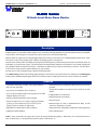
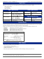
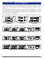
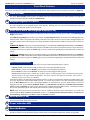
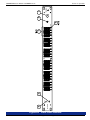
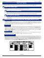
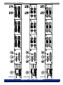
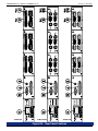
ALM26 Series
1U Audio Level Meter Alarm Monitor
Analog or Digital Inputs, Up To Twenty-Four
Channels, Loss-of-Audio/Clipping/Phase
Monitoring, with Audible and Visual Alarm
and 26-Segment Hi-Resolution Level Meters
Document P/N 821644 Rev-A
User Manual
CONTENTS
Title and Contents ........................................................... 1
Introduction ............................................................................................ 2
Section 1: General Features and Specifications........ 3
Description and Features ....................................................................... 4
Applications, Specifications, Standard Models, and Other Options ...... 5
Rear Panel Configurations ..................................................................... 6
Section 2: Operation ....................................................... 7
Installation ............................................................................................. 9
Alarm Sounder Enable/Disable Instructions .......................................... 9
Front Panel Features .............................................................................. 10
Rear Panel Features ............................................................................... 12
Section 3: Technical Information ................................. 19
LED Bargraph Display Specifications .................................................. 20
ALM26 Internal Settings - Address, Peak Hold, PPM Characteristics... 20
Level Meter Alternative Scales ............................................................. 21
ALM26 (Analog) Interconnect Block Diagram ......................................... 22
ALM26 (Digital) Interconnect Block Diagram .......................................... 23
© 2006 Wohler Technologies Inc. ALL rights reserved
1
Important Safety Instructions
1)
Read these instructions.
2)
Keep these instructions.
3)
Heed all warnings.
4)
Follow all instructions.
5)
Do not use this apparatus near water.
6)
Clean only with dry cloth.
7)
Do not block any ventilation openings. Install in accordance with the manufacturer's instructions.
8)
Do not install near any heat source such as radiators, heat registers, stoves, or other apparatus (including
amplifiers) that produce heat.
9)
Do not defeat the safety purpose of the polarized or grounding-type plug. A polarized plug has two blades
with one wider than the other. A grounding type plug has two blades and a third grounding prong. The
wide blade or the third prong are provided for your safety. If the provided plug does not fit into your outlet,
consult an electrician for replacement of the obsolete outlet.
10) Protect the power cord from being walked on or pinched, particularly at plugs convenience receptacles
and the point where they exit from the apparatus.
11) Only use attachments/accessories specified by the manufacturer.
12) Use only with the cart stand, tripod, bracket, or table specified by the manufacturer, or sold with the
apparatus. When a cart is used, use caution when moving the cart/apparatus combination to avoid injury
from tip-over.
13) Unplug this apparatus during lightning storms or when unused for long periods of time.
14) Refer all servicing to qualified service personnel. Servicing is required when the apparatus has been
damaged in any way, such as when power-supply cord or plug is damaged, liquid has been spilled or
objects have fallen into the apparatus, the apparatus has been exposed to rain or moisture, does not
operate normally, or has been dropped.
15) Do not expose this apparatus to rain or moisture.
16) The apparatus shall be connected to a mains socket outlet with a protective earthing connection.
CAUTION!
In products featuring an audio amplifier and speakers, the surface at the side of the
unit, where the audio amplifier heat sink is internally attached, may get very hot after
extended operation. When operating the unit excercise caution when touching this
surface and ensure that external materials which may be adversely affected by heat
are not in contact with it. There is a Hot Surface label (see diagram) attached to the
aforementioned surface of the product.
Introduction
Congratulations on your selection of a Wohler Technologies product. We are confident it represents the best performance and value
available, and we guarantee your satisfaction with it.
If you have questions or comments you may contact us at:
Wohler Technologies, Inc.
31055 Huntwood Avenue
Hayward, CA 94544
Phone: (510) 870-0810
Fax: (510) 870-0811
US Toll-Free: 1-888-596-4537
www.wohler.com
2
[email protected]
© 2007 Wohler Technologies, Inc. ALL rights reserved
ALM26 Series User Manual P/N 821644 Rev-A
Section 1
General Features
and Specifications
Description
Features
Applications
Specifications
Standard Models
Other Options
© 2006 Wohler Technologies Inc. ALL rights reserved
3
ALM26 Series User Manual P/N 821644 Rev-A
Section 1: General Features and Specifications
ALM26 Series
1U Audio Level Meter Alarm Monitor
RESET
1
2
3
4
5
6
7
8
9
10
11
12
13
14
15
16
17
18
19
20
21
22
23
24
POWER
RESET
WOHLER
TECHNOLOGIES
ALM26-24D
ALL
ALM26-24Dxx Front Panel
Description
The Wohler ALM26 Series systems provide audio level metering and audible and visual alarms for loss of audio, over-range (clipping),
and phase/polarity reversal. When a fault condition occurs, it activates individual channel level meter LED behavior and sets off a mutable
acoustic alarm. It also energizes a rear-panel relay contact closure(s) for external alarm indication.
High-resolution 26-segment tri-color LED bargraph display level meters provide a choice of VU and PPM display characteristics. These
level meters are also used to display alarm conditions by flashing groups of red segments.
An alarm is activated by audio levels falling outside a pre-determined range for a pre-determined period of time. Each channel may be set
individually, or grouped in stereo pairs. Clip and loss alarms are independently indicated on each channel. Carrier alarms (digital units
only) and phase alarms are linked in stereo pairs. Individual reset buttons are provided for each channel, as well as a “reset all” button.
A Piezo buzzer sounds when any channel indicates any type of alarm.
The unit may by easily configured using a Windows-based application.
The ALM26 Analog models monitor analog signals and feature "mini" Phoenix stye input connectors as standard. The ALM26 Digital
models monitor AES/EBU digital signals with a choice of Phoenix, BNC, or XLR input connectors. Custom variations are available.
Features
• Centralized monitoring of facility-wide signal conditions
• Only one rack space high
• Channel pairs may be configured as either mono or stereo on a perpair basis
• Up to twenty-four channels can be monitored
• Visible alarm indication via LED level meter behavior for each
channel
• Up to twenty-four high-resolution 26-segment tri-color LED
bargraph display level meters
• Full duplex RS-232 control/status
• Analog or Digital (AES/EBU) models available
• Alarms for Signal Loss, Over-range (clipping), and Phase
(polarity) reversal. Alarm for loss-of-carrier (loss of
digital signal) is available on digital units.
• Individual channel reset buttons
• Reset All button
• Balanced inputs on "mini" or standard Phoenix, BNC, or XLR
connectors (depending on model)
• Adjustable level thresholds for alarm conditions
• Alarm parameters configurable with Windows-based application
• Audible piezo alarm (mutable)
• Power indication LED
NOTE: In the model names throughout this manual, the unspecified channel quantity is indicated by "nn", the unspecified stereo/
mono is indicated by "x", and unspecified connector option is indicated by "/x".
4
© 2006 Wohler Technologies Inc. ALL rights reserved
ALM26 Series User Manual P/N 821644 Rev-A
Section 1: General Features and Specifications
Applications
The ALM26 Series audio alarm monitor units are an adaptable and effective way to monitor any Analog or AES/EBU digital audio
application. The following are some of the applications where an ALM26 Series unit would prove valuable.
·
·
·
Radio Broadcast Station
TV Control Room
Remote Monitoring
Power Specifications
Input Specifications
AC mains power:
100-250 VAC, 50/60 Hz universal
input, auto switching
Power consumption:
25W
Input Sampling Rate:
32k - 48k Auto (AES)
Input Connector(s):
Analog: "Mini" Phoenix (standard)
AES/EBU: Phoenix (standard)
AES/EBU: BNC or XLR (optional)
AES Input Impedance:
Phoenix: 110 Ω, balanced
XLR:
110 Ω, balanced
BNC:
75 Ω, unbalanced
Dimensions (H x W x D): 1.75 x 19 x 8 inches
45 x 483 x 203 mm
>10K Ω, balanced
Weight:
Analog Input impedance:
Physical Specifications
8 lbs./3.5 kg
Standard Models
ALM26 Series models may be ordered with a choice of 8, 16, and 24 channels standard. Other channel quantities (up to 24) may be
ordered as special options. However, ALM26 Models utilizing XLR connector inputs are limited to twelve (12) or fewer channels
due to space constraints resulting from the comparatively large size of XLR connectors.
NOTE: In the model names below and throughout this manual, the unspecified channel quantity is indicated by "nn".
ALM26-nnA:
ALM26-nnD:
ALM26-nnD/B:
ALM26-nnD/X:
Analog inputs on "mini" Phoenix connectors
Digital (AES/EBU) inputs on standard Phoenix connectors
Digital (AES/EBU) inputs on BNC connectors
Digital (AES/EBU) inputs on XLR connectors
Model Option Naming Key
1st Appended Letter........... Signal
2nd Appended
Letter............................. Connector
Analog
{ AD ==Digital
(none) = Phoenix (3-Pin Male)
/B = BNC (Female)
/X = XLR (3-Pin Female)
{
NOTE: Analog models use 6-pin "mini" Phoenix connectors,
Digital models use standard 3-pin Phoenix connectors.
Other Options
Other options are available by special order including:
• Custom combinations of input connectors
• 53-segment high resolution displays in 2U rack size
• Alternative color boundries
Other custom options are possible. Call your dealer or Wohler Technologies to discuss your specific needs.
Units are designed to meet, at time of manufacture, all currently applicable product safety and EMC requirements, such as those of
CE. Features and specifications subject to improvement without notice.
© 2006 Wohler Technologies Inc. ALL rights reserved
5
ALM26 Series User Manual P/N 821644 Rev-A
Section 1: General Features and Specifications
Rear Panel Configurations
The 1U ALM26 rear panels are comprised of modular panel sections. In any given ALM26 model, from one to three of the modular
panel sections contain the audio input connectors (unused sections have blank panels), with a fourth remaining section containing the
alarm controller features. This arrangement permits mixing of different types of input modules, although such mixes are considered
special order items. The number of channels is designated by a number following the ALM26 (i.e., ALM26-24 = twenty-four
channels).
The following illustration shows three types of input panel section modules (two digital and one analog) available for use in the ALM26
Series. Analog models are referred to with an "A" appended to the standard product name and Digital (AES) models are referred to with
a "D" appended. Models featuring Phoenix connector inputs do not append any letter to the model name as these connectors are
considered standard. BNC connector inputs append a "/B" to the model name and XLR connector inputs append an "/X". See page 5
for a list of all standard models in the ALM26 series.
AES (110 )
TERM
TERM
CH A
AES
75
CH B
3-4
TERM
TERM
CH A
AES
CH B
CALIB
1-2
TERM
CH A
CH B
AES
75
TERM
CH A
AES
75
TERM
CH B
CALIB
Please note that XLR models are limited to twelve channels (or less) due to space constraints when using the larger XLR connectors.
75
7-8
5-6
TERM
BNC Input Modular Section
for ALM26-nnD/B
Phoenix Input Modular Section
for ALM26-nnD
"Mini" Phoenix Input Modular Section
for ALM26-nnA
Below are examples showing three standard configurations of the ALM26 series rear panels for twenty-four channel units.
AES (110 )
AES (110 )
AES (110 )
PORT 1
INTERNAL POWER
19
20
TERM
17
18
11
12
21
22
15
16
TERM
TERM
9
10
3
4
13
14
7
8
1
2
TERM
TERM
UNDERWRITERS LABS
SEE POWER SUPPLY
LABEL ON SIDE
TERM
RS232
OPT
23
24
TERM
TERM
TERM
5
6
TERM
TERM
TERM
ALM26-24D Rear Panel (24-Channel Digital with Standard Phoenix Inputs)
19-20
17-18
TERM
TERM
AES
11-12
AES
75
75
9-10
TERM
TERM
AES
3-4
75
TERM
TERM
AES
75
23-24
INTERNAL POWER
15-16
RS232
OPT
AES
AES
75
UNDERWRITERS LABS
SEE POWER SUPPLY
LABEL ON SIDE
75
TERM
TERM
AES
75
21-22
PORT 1
AES
75
TERM
TERM
AES
75
1-2
TERM
TERM
AES
AES
75
AES
75
75
13-14
5-6
7-8
CH B
CALIB
CH A
23-24
CH A
CH A
17-18
11-12
21-22
15-16
CH B
CH A
CH B
CH B
CH A
CH A
CH B
CH A
9-10
3-4
13-14
7-8
CH B
CH B
CALIB
CH B
PORT 1
CH A
INTERNAL POWER
CH B
UNDERWRITERS LABS
SEE POWER SUPPLY
LABEL ON SIDE
1-2
CH A
CH B
CALIB
CH A
CALIB
CH B
19-20
CALIB
CH A
CALIB
ALM26-24D/B Rear Panel (24-Channel Digital with BNC Inputs)
OPT
CH A
RS232
CH B
5-6
ALM26-24A Rear Panel (24-Channel Analog with "mini" Phoenix Inputs)
6
© 2006 Wohler Technologies Inc. ALL rights reserved
ALM26 Series User Manual P/N 821644 Rev-A
Section 2
Operation
Installation
Alarm Sounder Enable/Disable Instructions
Front Panel Features
Rear Panel Features
© 2006 Wohler Technologies Inc. ALL rights reserved
7
ALM26 Series User Manual P/N 821644 Rev-A
(This page intentionally left blank)
8
© 2006 Wohler Technologies Inc. ALL rights reserved
Section 2: Operation
ALM26 Series User Manual P/N 821644 Rev-A
Section 2: Operation
Installation
Mounting
The unit should be mounted where convenient for operating persons, ideally at approximately eye level for best visual monitoring.
Heat Dissipation
No special considerations for cooling are necessary as long as the ambient temperature inside the rack area does not exceed
approximately 40°C (104°F).
Mechanical Bracing
The chassis is securely attached to the front panel at five points along its surface, not just at the four corners of the chassis ears.
This feature will reduce or eliminate rear bracing requirements in many mobile/portable applications. The weight of internal
components is distributed fairly evenly around the unit.
Audio Connections
Connection of the audio feeds is straightforward. Please refer to the system interconnect block diagram on pages 22 and 23 for
clarification of the general signal paths into the ALM26 series units.
Care should be exercised to avoid mismatched cable types and other similar causes of undesired reflections in RF signal systems.
Electrical Interference
As with any audio equipment, maximum immunity from electrical interference requires the use of shielded cable; however,
satisfactory results can sometimes be obtained without it. The internal circuitry common is connected to the chassis.
AC Power
The unit's AC mains connection is via a standard IEC inlet, with safety ground connected directly to the unit's chassis. The
universal AC input (100-240VAC, 50/60Hz) switching power supply is a self-resetting sealed type, with automatic over-voltage
and over-current shutdown. There is no user-replaceable fuse in either the primary or secondary circuit.
Alarm Sounder Enable/Disable Instructions
All ALM53 Series units feature a Piezo Alarm Sounder located on the front panel (Item 1, page 10). This sounder produces an audible
alarm when any channel goes into any alarm condition. This sounder may be disabled or enabled using the instructions below. The
sounder may also be enabled and disabled with the WAC software (see Section 5.6, System Settings in the WAC manual for details).
To ENABLE the acoustic sounder in the unit, perform the following steps on the front panel:
1) Hold down the Reset All button (Item 6, page 10)
2) Press and release the Channel 3 Reset Alarm button (Item 4, page 10)
3) Release the Reset All button
To DISABLE the acoustic sounder in the unit, perform the following steps on the front panel:
1) Hold down the Reset All button (Item 6, page 10)
2) Press and release the Channel 1 Reset Alarm button (Item 4, page 10)
3) Release the Reset All button
© 2006 Wohler Technologies Inc. ALL rights reserved
9
ALM26 Series User Manual P/N 821644 Rev-A
Section 2: Operation
Front Panel Features
Please refer to the example in Figure-2a on the following page to familiarize yourself with the front panel features of the ALM26
Series units covered by this manual. The following sections describe these functions and are referenced, by number, to Figure-2a.
1
Alarm Sounder
This piezo Alarm Sounder speaker produces an audible alarm when any channel detects any alarm condition. See page 9 for
instructions for how to disable or enable the Alarm Sounder.
2
Bargraph Brightness Trim Pot
This control is recessed into the front panel and can be accessed using a small screwdriver. Turning it clockwise will increase
the relative brightness of the bargraph display LED segments. Adjusting this one control will simultaneously affect the
brightness of all bargraph displays on the front panel.
3
Audio Level Meter LED Bargraph Displays (1-24)
Audio levels for the audio input sources are displayed via these 26-segment tri-color (green, amber, red) LED Bargraph
Display level meters.
Each LED Bargraph Display represents a single channel. Each Reset Button (Item 4), located above the LED bargraphs, has a
channel number, which corresponds to the numbers found next to the input connectors on the rear panel. Bargraph displays are
arranged in groups of four on the front panel, four being the number of input channels available in each input section on the rear
panel.
ALM26-nnD (Digital): Each group of four bargraph displays is user adjustable for Reference Level calibration and PPM/VU
Display Mode via a DIP switch module on the rear panel. This DIP switch module is located between the two input connectors in
each input section on the rear panel. See Item B, page 12 for more information regarding the rear panel DIP switch locations and
settings.
ALM26-nnA (Analog): Each group of four bargraph displays is user adjustable for Reference Level calibration and PPM/VU
Display Mode via a DIP switch module on the rear panel. This DIP switch module is located between the two input connectors in
each input section on the rear panel. See Item D, page 14 for more information regarding the rear panel DIP switch locations and
settings.
Alarm Indication Behavior
Alarm conditions are indicated by lit LEDs in the 26-segment LED bargraph displays as follows:
• Clipping Alarm is indicated in the Top one third region of the bargraph LED segments.
• Phase Alarm is indicated in the Middle one third region of the bargraph LED segments.
• Loss of Audio is indicated in the Bottom one third region of the bargraph LED segments.
• Carrier Loss in a digital unit is indicated by all three regions of LED segments in the left channel, and the top and
bottom regions in the right channel turning RED. The center region on the right side is left dark. This creates a
flashing red “C” between the two channels.
In an alarm condition, the applicable bargraph LED segments (see above) will alternately flash between RED and the color
previously displayed in the individual LED segments. To reset the alarm behavior for each individual LED bargraph,
press the Reset Button directly above the bargraph (Item 4). To simultaneously reset the alarm behavior of ALL the
bargraphs in the unit, press the Reset All Button (Item 6). See Alarm Resets in Section 7.0 in the Wohler Alarm Controller
(WAC) manual (P/N 821642) for details on reset function modes available through the WAC software. Note that these buttons
also reset the peak-hold segment when manual peak hold mode is enabled (see page 20).
NOTE: Each of the alarm features described above may be enabled or disabled on a per channel basis or on a unit wide
basis through the WAC (Wohler Alarm Control) software. See Setting Alarm Channel Parameters, Section 5.5 and
System Settings, Section 5.6 in the WAC manual (P/N 821642) for details.
4
Reset Button (1-24)
These momentary push-buttons reset the level meter alarm function for each individual channel. When a button is pushed, only
the level meter located directly below it is reset.
5
Power Indication LED
This LED lights up GREEN to indicate the ALM26 Series model is connected to operational mains power.
6
Reset All Button
This momentary push-button simultaneously resets the level meter alarm function for ALL the channels in the unit. Note that
this button will also reset the peak-hold segment of all the meters with manual peak hold mode enabled (see page 20).
10
© 2006 Wohler Technologies Inc. ALL rights reserved
ALM26 Series User Manual P/N 821644 Rev-A
Section 2: Operation
WOHLER
TECHNOLOGIES
1
2
4
RESET
1
2
3
3
4
5
6
7
8
9
10
11
12
13
14
15
16
17
18
19
20
21
22
23
24
5
POWER
RESET
ALL
ALM26-24D
6
Figure-2a: Front Panel Features
© 2006 Wohler Technologies Inc. ALL rights reserved
11
ALM26 Series User Manual P/N 821644 Rev-A
Section 2: Operation
Rear Panel Features
Please refer to Figure-2b on the following page to familiarize yourself with the rear panel features of the ALM26 Series units
covered by this manual. The following sections describe these features and are referenced, by letter, to Figure-2b.
A
Digital (AES) Audio Inputs
(ALM26-nnD Only)
Each input connector receives an AES digital signal from which two channels are derived.
A1 Phoenix Connectors (Standard)
These Phoenix (or XLR) connectors are configured for a balanced (110 Ω impedance) connection. Channel numbers are
displayed on a label to the side of each connector and correspond to the channel numbers above the associated LED
indicators on the front panel. Connector pinout information is silk-screened just below each connector.
A2 BNC Connectors (Optional)
These BNC connectors are configured for an unbalanced (75 Ω impedance) connection. Channel numbers displayed
on a label above or below each connector and correspond to the channel numbers above the associated LED indicators
on the front panel.
B
Digital AES Termination, Reference Level, and Display Mode DIP Switch
(ALM26-nnD Only)
This DIP switch sets the Termination for the input connectors, and the bargraph Display Mode and Reference Level for the
associated bargraph displays. Each DIP switch module affects only the four channels (two input connectors) within the
section in which it is located. See the descriptions and diagram below for setting information.
Termination:
Switch sections 1 (left connector) and 6 (right connector) respectively set the termination for the connector inputs in each 4channel input section. The respective DIP switch section should be moved to the UP position to UNTERMINATE the
connector if the input signal is fed to downstream equipment. The respective DIP switch section should be moved to the
DOWN position to TERMINATE the connector if the input signal is not fed to downstream equipment. The factory default
setting is TERMINATED for each input connector. See diagam below for settings.
Reference Level:
DIP switch sections 2 and 3 determine the Reference Level, which adjusts the level of the input signal and the resultant level
displayed on the LED bargraphs. Factory setting is -20 dBfs. See diagam below for settings.
Bargraph Display Modes:
DIP switch sections 4 and 5 determine how peak levels are displayed for the four associated meters on the front panel. There
are four possible settings; VU Bargraph Only, VU Bargraph with PPM Floating Segment, PPM Bargraph Only, and
PPM Bargraph with PPM Floating Segment. The factory default setting is VU Bargraph with PPM Floating Segment.
See diagam below for settings. See the ALM26 Internal Settings - Address, Peak Hold, PPM Characteristics diagram
on page 23 for how to set the Peak Hold and PPM Ballistics characteristics.
(Continued)
12
© 2006 Wohler Technologies Inc. ALL rights reserved
TERM
TERM
AES (110 )
TERM
TERM
17-18
17
18
21
22
11
12
15
16
11-12
TERM
TERM
AES (110 )
TERM
TERM
TERM
TERM
9-10
9
10
13
14
3
4
7
8
3-4
TERM
TERM
AES (110 )
TERM
TERM
TERM
TERM
TERM
TERM
1-2
1
2
5
6
5-6
1-2
75
AES
AES
AES
AES
5-6
CH B
CH B
AES
CH A
75
AES
CH B
CH A
75
7-8
CH A
CH B
75
3-4
7-8
CH A
75
9-10
13-14
OPT
OPT
OPT
PORT 1
PORT 1
PORT 1
RS232
RS232
RS232
INTERNAL POWER
UNDERWRITERS LABS
SEE POWER SUPPLY
LABEL ON SIDE
INTERNAL POWER
UNDERWRITERS LABS
SEE POWER SUPPLY
LABEL ON SIDE
INTERNAL POWER
UNDERWRITERS LABS
SEE POWER SUPPLY
LABEL ON SIDE
13
© 2006 Wohler Technologies Inc. ALL rights reserved
19
20
23
24
TERM
TERM
13-14
CH B
CH B
AES
AES
TERM
TERM
CH A
75
AES
CH B
CH A
75
15-16
CH A
CH B
75
11-12
15-16
CH A
75
17-18
21-22
CALIB
19-20
21-22
CH B
CH B
AES
TERM
TERM
CH A
AES
CH B
CH A
CALIB
75
CH A
CH B
CALIB
75
23-24
CH A
CALIB
AES
75
19-20
23-24
CALIB
ALM26-24D
ALM26-24D/B
ALM26-24A
CALIB
Section 2: Operation
ALM26 Series User Manual P/N 821644 Rev-A
Figure-2b: Rear Panel Features
ALM26 Series User Manual P/N 821644 Rev-A
Section 2: Operation
Rear Panel Features
(Continued)
C
Analog Audio Inputs
(ALM26-nnA Only)
The Analog units have balanced (>10K Ω impedance) inputs terminated in 6-pin "mini" Phoenix connectors. There are two
separate analog signals; one signal to the left three pins (CH A) and the second signal to the right three pins (CH B). There are two
input connectors per input section (4 channels). Channel numbers are displayed on a label to the side of each connector and
correspond to the channel numbers above the associated bargraph meters on the front panel. Pin-out information is silk-screened on
the rear panel directly below each connector.
D
Analog Line Level, Reference Level, and Display Mode DIP Switch
(ALM26-nnA Only)
This DIP switch sets the Line Level Calibration, Reference Level, and PPM/VU Display Mode. Each DIP switch module
affects only the four channels within the section in which it is located. See the descriptions and diagram below for setting
information.
Line Level (Auto) Calibration:
The unit is calibrated at the factory. To recalibrate:
1) Turn on the power.
2) Apply the desired reference level (nominal 0) signal to all four channels.
3) Make sure the Reference Level DIP sections (2 and 3) are set to the nearest level of the input signal being applied for
calibration (i.e., 0, +4, +6 or +8). The user should make sure that the signal applied to all four channels is within +/- 4 dB of the
reference level selected by DIP switch sections 2 and 3.
4) Place DIP section 1 in the DOWN position.
5) Wait 10 seconds. The unit will remove the previous calibration and the new calibration will be applied.
6) Place DIP section 1 in the UP position and return unit to service.
7) Only ONE auto-calibration attempt may be made for each cycling of AC power to the unit. Once the Line Level Calibration
DIP switch has been placed in the CAL position, it is necessary to cycle the power before that DIP switch will be functional again,
EVEN if a calibration attempt was unsuccessful.
If one wishes to calibrate again, turn off the power to the unit and repeat steps 1 through 6.
Reference Level:
DIP switch sections 2 and 3 determine the Reference Level, which adjusts the level of the input signal and the resultant level
displayed on the LED bargraphs. Factory setting is +4 dB. See diagram below for settings.
Bargraph Display Mode:
DIP switch sections 4 and 5 determine how peak levels are displayed for the four associated meters on the front panel.
There are four possible settings; VU Bargraph Only, VU Bargraph with PPM Floating Segment, PPM Bargraph
Only, and PPM Bargraph with PPM Floating Segment. The factory default setting is VU Bargraph with PPM Floating
Segment. See diagam below for settings. See the ALM26 Internal Settings - Address, Peak Hold, PPM Characteristics
diagram on page 23 for how to set the Peak Hold and PPM Ballistics characteristics.
NOTE: For more accurate indication of signal levels, analog meters are tuned to effect a “rounding” function which occur BETWEEN the
thresholds of any two bargraph segments. This means the level meter zero LED segment will turn on at one-half the smallest spacing between
LED segments (mid-scale resolution) before that segment's scale indication. This "rounding offset" is 0.5 dB for the Analog (extended VU),
Digital, Nordic, BBC, and DIN scales. It is 0.25 dB for the VU scale. For example, using the Analog (extended VU) scale, a meter
calibrated for a +4 dBu nominal level will actually turn the zero LED segment of the level meter on at 3.5 dBu and all segments will turn on at
0.5 dBu before that segment's silk-screened scale indication.
(Continued)
14
© 2006 Wohler Technologies Inc. ALL rights reserved
TERM
TERM
AES (110 )
TERM
TERM
TERM
TERM
17-18
21
22
17
18
15
16
11
12
11-12
TERM
TERM
AES (110 )
TERM
TERM
TERM
TERM
9-10
13
14
9
10
7
8
3
4
3-4
TERM
TERM
AES (110 )
TERM
TERM
TERM
TERM
1-2
1
2
5
6
75
1-2
5-6
OPT
OPT
OPT
PORT 1
PORT 1
PORT 1
RS232
RS232
RS232
INTERNAL POWER
UNDERWRITERS LABS
SEE POWER SUPPLY
LABEL ON SIDE
INTERNAL POWER
UNDERWRITERS LABS
SEE POWER SUPPLY
LABEL ON SIDE
INTERNAL POWER
UNDERWRITERS LABS
SEE POWER SUPPLY
LABEL ON SIDE
15
© 2006 Wohler Technologies Inc. ALL rights reserved
19
20
23
24
19-20
CH B
AES
AES
TERM
TERM
AES
AES
CH B
AES
AES
5-6
AES
7-8
CH A
CH B
75
3-4
7-8
CH A
75
9-10
13-14
CH B
AES
TERM
TERM
13-14
CH A
AES
AES
CH B
CH B
CALIB
AES
CH A
CH B
CALIB
75
CH A
CALIB
75
11-12
15-16
CH B
75
15-16
CH A
75
21-22
CH B
75
TERM
TERM
CH A
17-18
21-22
CH A
75
CH B
CH B
CH A
75
CH A
CH B
CH A
75
23-24
CH A
CALIB
AES
75
19-20
23-24
CALIB
ALM26-24D
ALM26-24D/B
ALM26-24A
CALIB
Section 2: Operation
ALM26 Series User Manual P/N 821644 Rev-A
Figure-2b: Rear Panel Features
ALM26 Series User Manual P/N 821644 Rev-A
Section 2: Operation
Rear Panel Features
(Continued)
E
Option Select Switch
This 10-position BCD (Binary Coded Decimal) rotary switch is used to set operation of the unit. It can be accessed using
a small flathead screwdriver or similar tool. See table below for settings.
Please note that choosing alternate scales may require a change to the scale indication silk-screening next to the bargraph
display level meters on the front panel. See page 24 (Level Meter Alternative Scales) for more information.
F
Port 1 Connector
This DB-25 connector (Port 1) is used to convey alarm conditions
to outboard equipment. This port has isolated contact closures,
which indicate Alarm conditions for the associated channel or
channel pair. These contacts are normally open and close on
alarm.
In units with twelve or fewer channels, each relay represents a
single channel. In units with more than twelve channels, each
relay represents a pair of channels.
A summary contact pair exists between pins 1 and 14. If any
relay pair in the unit closes, the summary contacts also close.
Example: If channel 15 or 16 trips into alarm, a contact closure
will occur between pins 9 and 21 and between pins 1 and 14 for
the duration of the alarm.
See the table to the right for connector pinout details.
NOTE: An option is available to make the relay operation
independent of the alarm indications and resets. Contact the
factory for details and instructions on enabling this option.
G
Serial Control Connector
This connector is used for Remote Control and for software upgrades of the product. See table below for pinout information.
H
Power Input Connector
Attach a standard IEC-320 power cord between this connector and mains power (100 - 240VAC nominal, 50/60 Hz). The
front panel Power Indication LED (Item 5, page 10) will glow GREEN to indicate operating voltages are present.
16
© 2006 Wohler Technologies Inc. ALL rights reserved
TERM
TERM
AES (110 )
TERM
TERM
TERM
TERM
17-18
21
22
17
18
15
16
11
12
11-12
TERM
TERM
AES (110 )
TERM
TERM
TERM
TERM
9-10
13
14
9
10
7
8
3
4
3-4
TERM
TERM
AES (110 )
TERM
TERM
TERM
TERM
1-2
1
2
5
6
75
1-2
5-6
OPT
OPT
OPT
PORT 1
PORT 1
PORT 1
RS232
RS232
RS232
INTERNAL POWER
UNDERWRITERS LABS
SEE POWER SUPPLY
LABEL ON SIDE
INTERNAL POWER
UNDERWRITERS LABS
SEE POWER SUPPLY
LABEL ON SIDE
INTERNAL POWER
UNDERWRITERS LABS
SEE POWER SUPPLY
LABEL ON SIDE
17
© 2006 Wohler Technologies Inc. ALL rights reserved
19
20
23
24
19-20
CH B
AES
AES
TERM
TERM
75
AES
CH B
AES
AES
5-6
75
7-8
CH A
CH B
75
3-4
7-8
CH A
75
9-10
13-14
CH B
AES
TERM
TERM
13-14
CH A
75
AES
CH B
CH B
CALIB
AES
CH A
CH B
CALIB
75
CH A
CALIB
75
11-12
15-16
CH B
AES
15-16
CH A
75
21-22
CH B
AES
TERM
TERM
CH A
17-18
21-22
CH A
75
CH B
CH B
CH A
AES
CH A
CH B
CH A
75
23-24
CH A
CALIB
AES
75
19-20
23-24
CALIB
ALARM-24D
ALARM-24D/B
ALARM-24A
CALIB
Section 2: Operation
ALM26 Series User Manual P/N 821644 Rev-A
Figure-2b: Rear Panel Features
ALM26 Series User Manual P/N 821644 Rev-A
(This page intentionally left blank)
18
© 2006 Wohler Technologies Inc. ALL rights reserved
Section 2: Operation
ALM26 Series User Manual P/N 821644 Rev-A
Section 3
Technical Information
LED Bargraph Display Specifications
ALM26 Internal Settings - Address, Peak Hold, PPM Characteristics
Level Meter Alternative Scales
ALM26 (Analog) Interconnect Block Diagram
ALM26 (Digital) Interconnect Block Diagram
© 2006 Wohler Technologies Inc. ALL rights reserved
19
ALM26 Series User Manual P/N 821644 Rev-A
Section 3: Technical Information
LED Bargraph Display Specifications
Level meter type:
LED bargraph
Segment quantity:
26
Level gain (DIP switch selectable):
0, +4, +6, +8 dB
Bargraph Length:
1.078" (27.85 mm)
LED segment size:
0.14" x 0.028" (3.57 x 0.7 mm)
LED segment pitch:
0.041" (1.05 mm)
Segment display color:
Tri-color (red, amber, green)
Peak emmision wavelength:
Green: 570 nm, Red: 630 nm
Segment brighness, (If = 20 mA):
3.5 mcd
Segment brightness, uniformity:
<10% difference between segments
Adjacent segment "Off" brightness:
<1% of brightness of active segment
Notes:
1) For level meter Input Reference and Display Mode settings, see pages 12 (Digital) and 14 (Analog).
2) For level meter Addressing, Peak Hold, and PPM Characteristics settings, see this page, below.
3) For level meter Alternate Scales information, see page 21.
ALM26 Internal Settings - Address, Peak Hold, PPM Characteristics
ALM26 Internal 10-Position DIP Switch Settings
Address (Factory Set)
Peak Hold (Bargraph Display)
PPM Ballistics (Bargraph Display)
5 6
1 2 3 4
7 8
Peak Hold - Manual
Channels 1 to 4
1 2 3 4 5 6 7 8 9 10
1 2 3 4 5 6 7 8 9 10
IEC268-10, Type 1
1 2 3 4 5 6 7 8 9 10
5 6
1 2 3 4
7 8
Channels 5 to 8
1 2 3 4 5 6 7 8 9 10
IEC268-10, Type 2
Peak Hold - 3 Second
1 2 3 4 5 6 7 8 9 10
1 2 3 4
1 2 3 4 5 6 7 8 9 10
7 8
5 6
Channels 9 to 12
1 2 3 4 5 6 7 8 9 10
DIN 45406
Peak Hold - 10 Second
1 2 3 4 5 6 7 8 9 10
1 2 3 4
1 2 3 4 5 6 7 8 9 10
7 8
5 6
Peak Hold - Off
Channels 13 to 16
1 2 3 4 5 6 7 8 9 10
1 2 3 4 5 6 7 8 9 10
Single Sample Return
Time (SSRT)
1 2 3 4 5 6 7 8 9 10
1 2 3 4
Factory Settings
Channels 17 to 20
1 2 3 4 5 6 7 8 9 10
10
9
1 2 3 4
Channels 21 to 24
RM (Not Used)
PC (Not Used)
1 2 3 4 5 6 7 8 9 10
1 2 3 4 5 6 7 8 9 10
1 2 3 4 5 6 7 8 9 10
Note: DIP switch is located on Analog Input PCB (919174) or Digital Input PCB (919175) .
NOTE: The Peak Hold feature (if enabled) will only be visible if a floating segment
is also enabled (see Bargraph Display Modes sections on pages 12 and 14).
PPM Characteristics (Ballistics):
The PPM characteristics determine the Integration Time (rise time) and Return Time (fall time) of the level meter. The
Integration Time is the time it takes for the lighted segments of the level meter, after application of a 5 Khz tone at a certain
reference level, to rise within a specified number of dB of that level. Return Time is the time it takes for the lighted segments of
the level meter to fall a certain number of dB after removal of a 5 Khz tone of a certain reference level. The PPM characteristics
available for selection using DIP switch sections 7 and 8 of the 10-position Internal DIP Switch (as shown in the above diagram)
are as follows:
20
IEC268-10, Type 1:
Integration Time is 5 ms (-2 dB),
Return Time is 1.7 seconds (20 dB)
IEC268-10, Type 2:
Integration Time is 10 ms (-2 dB),
Return Time is 2.8 seconds (24 dB)
DIN 45406:
Integration Time is 5 ms (-2 dB),
Return Time is 1.5 seconds (20 dB)
Single Sample:
Integration Time is a single sample,
Return Time is 1.5 seconds (20 dB)
© 2006 Wohler Technologies Inc. ALL rights reserved
ALM26 Series User Manual P/N 821644 Rev-A
Level Meter Alternative Scales
The standard scales used on the ALM26 Series level meters are the Extended VU scale for analog models and AES scale for digital
models (see diagram below). However, if alternative scale characteristics are selected for the level meters using the Option Select
Switch (Item F, page 16), it is recommended that a label with the appropriate scale be applied to the front panel LED bargraph level
meters. Alternative scales include the VU, BBC, NORDIC, and DIN scales (see diagram below for scale comparison). Contact
Wohler Technologies for information about alternative scale labels for the ALM26 Series units. Note that the color boundaries for all
of the scales (standard and non-standard) can be modified. Contact the factory for instructions.
0
1
2
3
4
5
6
7
8
9
10
11
12
13
14
15
16
17
18
19
20
21
22
23
24
25
26
-6
-12
-18
-24
-30
-36
-42
-48
AES
(Digital)
Scale
(Standard)
1
2
3
4
5
6
7
8
9
10
11
12
13
14
15
16
17
18
19
20
21
22
23
24
25
26
+12
+6
0
-6
-12
-18
-24
-30
-40
-50
Extended VU
(Analog)
Scale
(Standard)
1
2
3
4
5
6
7
8
9
10
11
12
13
14
15
16
17
18
19
20
21
22
23
24
25
26
0
-3
-6
-9
-12
-15
-18
-21
-24
-27
-30
-40
-50
Alternate AES
Scale
(Custom)
+3
1
2
3
4
5
6
7
8
9
10
11
12
13
14
15
16
17
18
19
20
21
22
23
24
25
26
+2
+1
0
-1
-2
-3
-5
-7
-10
-20
VU
Scale
1
2
3
4
5
6
7
8
9
10
11
12
13
14
15
16
17
18
19
20
21
22
23
24
25
26
7
6
5
4
3
2
1
BBC
Scale
© 2006 Wohler Technologies Inc. ALL rights reserved
+12
1
2
3
4
5
6
7
8
9
10
11
12
13
14
15
16
17
18
19
20
21
22
23
24
25
26
+9
+6
+3
T
-3
-6
-9
-18
-24
-30
-36
-42
NORDIC
Scale
1
2
3
4
5
6
7
8
9
10
11
12
13
14
15
16
17
18
19
20
21
22
23
24
25
26
+5
0
-5
-10
-20
-30
-40
-50
DIN
Scale
21
ALM26 (Analog)
Interconnect Block Diagram
ALM26 Series User Manual P/N 821644 Rev-A
22
© 2006 Wohler Technologies Inc. ALL rights reserved
Section 3: Technical Information
Section 3: Technical Information
ALM26 (Digital) Interconnect Block Diagram
ALM26 Series User Manual P/N 821644 Rev-A
© 2006 Wohler Technologies Inc. ALL rights reserved
23
ALM26 Series User Manual P/N 821644 Rev-A
Wohler Technologies, Inc.
Wohler
31055Technologies,
Huntwood Avenue Inc.
31055
Huntwood
Avenue
Hayward,
CA 94544
Hayward,
CA(510)
94544
1-888-596-4537
Fax:
870-0811
web:
www.wohler.com
Phone: (510)
870-0810
Fax: (510) 870-0811
e-mail:
[email protected]
US Toll-Free:
1-888-596-4537
www.wohler.com [email protected]
24
© 2006 Wohler Technologies Inc. ALL rights reserved