1
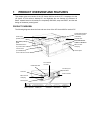
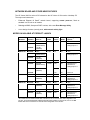
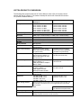
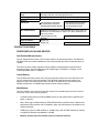
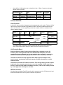
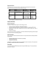
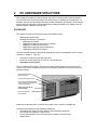
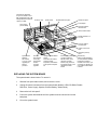
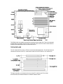
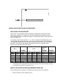
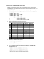
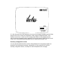
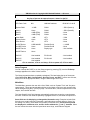
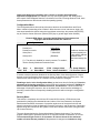
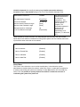
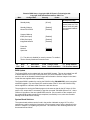
Familiarization Guide
HP Vectra XM 5/xx
series 4 PC
This guide is for experienced HP Support Center personnel CEs and reseller technicians.
That is, personnel who have already completed the HP Vectra PC family training course, or
equivalent, and have at least six months of experience servicing the HP Vectra PCs.
It is a self-paced training guide designed to train you to install, configure, and repair the PC.
You can follow it without having any equipment available.
Table of Contents
1 PRODUCT OVERVIEW AND FEATURES
4
PRODUCT OVERVIEW
NETWORK BOARD AND OTHER NEW FEATURES
MODELS AVAILABLE AT PRODUCT LAUNCH
VECTRA PRODUCTS COMPARISON
PRODUCT FEATURES
PROCESSOR-LOCAL BUS DEVICES
PCI BUS DEVICES
ISA BUS DEVICES
SOFTWARE
DOCUMENTATION
CHECKPOINT: PRODUCT OVERVIEW AND FEATURES
4
5
5
6
7
7
8
9
10
11
12
2 PC HARDWARE STRUCTURE 13
PACKAGING
REPLACING THE SYSTEM BOARD
THE BACKPLANE
INSTALLING OR REPLACING ACCESSORIES
REPLACING THE PROCESSOR
INSTALLING OR REPLACING MAIN MEMORY MODULES
UPGRADING TO 2 MB OF VIDEO MEMORY
INSTALLING OR REPLACING MASS-STORAGE DRIVES
INSTALLING THE D3979A COAX ADAPTER
CHECKPOINT: PC HARDWARE STRUCTURE
13
14
15
16
16
16
17
17
17
18
3 TROUBLESHOOTING AND REPAIR 20
SYSTEM ROM AND SECURITY SUPPORT
HP BIOS
CHECKPOINT: TROUBLESHOOTING AND REPAIR
A CHECKPOINT ANSWERS
20
20
27
28
CHECKPOINT ANSWERS
28
B FINAL TEST 31
FINAL TEST
D ANSWERS TO THE FINAL TEST
ANSWERS TO THE FINAL TEST
31
33
33
NOTICE
Information contained in this document is subject to change without notice.
Hewlett-Packard makes no warranty of any kind with regard to this material, including, but not
limited to, the implied warranties of merchantability and fitness for a particular purpose.
Hewlett-Packard shall not be liable for errors contained herein or for incidental or
consequential damages in connection with the furnishing, performance, or use of this material.
Hewlett-Packard shall not be liable for errors contained herein or for incidental or
consequential damages in connection with the furnishing, performance, or use of this material.
Hewlett-Packard assumes no responsibility for the use or reliability of its software on
equipment that is not furnished by Hewlett-Packard.
This document contains proprietary information which is protected by copyright. All rights are
reserved. No part of this document may be photocopied, reproduced, or translated into
another language without the prior written consent of Hewlett-Packard Company.
Centronics® is a U.S. registered trademark of Centronics Data Computer Corporation.
Microsoft®, Windows® and MS-DOS® are registered trademarks of Microsoft Corporation.
NextStep™ is a trademark of Next Incorported.
Novell® and Netware® are registered trademarks of Novell Inc.
O/S2™ is a trademark of International Business Machines Corporation.
PENTIUM™ is a trademark of Intel Cor[oration.
SCO UNIX® is a registered trademark of the Santa Cruz Operation.
Solaris™ is a trademark of Sun Microsystems Incorporated.
SoundBlaster™ is a trademark of Creative Technology Limited.
©1996 Hewlett-Packard Company
1
PRODUCT OVERVIEW AND FEATURES
This chapter gives an overview of the HP Vectra XM 5/xx series 4 PC. It compares it to the
HP Vectra VL 5/xx series 4 desktop PC, and highlights the new features: the Ethernet 10
BaseT network board on all models; the completely new BIOS, setup and POST; and the new
design of the status (control) panel.
PRODUCT OVERVIEW
The following diagrams show the front and rear views of the HP Vectra XM 5/xx series 4 PC.
Power supply
Double-sided backplane
with 5 accessory slots
(4 standard)
Speaker position
Hard disk drive
New status (control)
panel
Enhanced Ethernet
10 Base T LAN board
Flexible disk drive in
top 3.5-inch shelf
BNC coax hole
metal plug
5.25-inch shelf
(for CD-ROM drive)
New I/O panel
Vacant 3.5/5.25-inch shelf
RJ-45 network
connector
IIdentification label
4 accessory slot
panel blanks
Cover lock
Power connector
BNC coax hole
metal plug
New I/O panel
Mouse Keyboard
Parallel port
Serial Port A
Serial Port B
Display
NETWORK BOARD AND OTHER NEW FEATURES
The HP Vectra XM 5/xx series 4 PC is based on the HP Vectra VL 5/xx series 4 desktop PC.
The major new features are:
•
Enhanced Ethernet 10 BaseT network board, supporting remote power-on, fitted as
standard in a PCI slot on all models.
•
Redesigned BIOS, Setup and POST routines, with a new Error Message Utility.
•
A new design of status (control) panel, with network activity light.
MODELS AVAILABLE AT PRODUCT LAUNCH
Platform*
Product
Number
Hard
Drive C:
Std.
RAM
Cache
MultiMedia
Operating
System
XM4 5/75
D3961A
None
8 MB
No
No
none
D3962A
840 MB
(D2908-60xxx)
1.2 GB
(D2930A)
D3963A
XM4 5/100
XM4 5/120
Windows for
Workgroups 3.11
D3964A
None
8 MB
D3965A
840 MB
(D2908-60xxx)
XM4 5/150
XM4 5/166
No
none
D3966A
1.2 GB
(D2930A)
D3967A
None
8 MB
Yes
No
none
D3968A
840 MB
(D2908-60xxx)
16 MB
Yes
No
Windows 95 or
Windows for
Workgroups 3.11
D3975A
1.2 GB
(D2930A)
Yes
No
Yes
No
OS/2 3.0
Windows for
Workgroups 3.11
D3975S
XM4 5/133
No
D3970A
None
8 MB
Yes
No
none
D3977A
1.2 GB
(D2930A)
16 MB
Yes
No
Windows 95 or
Windows for
Workgroups 3.11
D3972A
None
8 MB
Yes
No
none
D3978A
1.2 GB
(D2930A)
16 MB
Yes
No
Windows 95 or
Windows for
Workgroups 3.11
D4220A
None
8 MB
Yes
No
none
D4221A
1.2 GB
(D2930A)
16 MB
Yes
No
Windows 95 or
Windows for
Workgroups 3.11
*All models have an Enhanced IDE disk controller and an S3 Trio 64 Ultra VGA integrated on the
PCI bus, an Enhanced Ethernet 10BaseT Network board installed on the PCI bus, and a 1.44 MB
flexible disk drive connected to a controller that is integrated on the ISA bus.
VECTRA PRODUCTS COMPARISON
The following table compares the new HP Vectra XM 5/xx series 4 PC (in the white, central
column) with the HP Vectra VL 5/xx series 4 desktop PC and the HP Vectra XM 5/xx series 3
PC (in the two shaded columns).
Component
HP Vectra VL 5/xx series 4
Desktop PC
HP Vectra XM 5/xx series 4 PC
Microprocessor
5/90: Pentium 90 MHz
5/100: Pentium 100 MHz
5/120: Pentium 120 MHz
5/133: Pentium 133 MHz
5/150: Pentium 150 MHz (due)
5/166: Pentium 166 MHz (due)
5/75: Pentium 75 MHz
5/100: Pentium 100 MHz
5/120: Pentium 120 MHz
5/133: Pentium 133 MHz
5/150: Pentium 150 MHz
5/166: Pentium 166 MHz
Main memory
32-bit EDO (60 ns) modules
Standard
8 MB (a pair of 4 MB modules) or 16 MB (a pair of 8 MB modules)
Maximum
128 MB (chipset limitation)
Upgrades
Must be installed in pairs
Sockets
Six (3 banks, one pair in each)
Error protection
Not supported
Level 1 cache memory
8 KB for instruction-code, 8 KB for data (both caches on the
microprocessor)
Level 2 cache memory
256 KB synchronous pipeline
burst cache memory (socketed
on system board)
256 KB synchronous pipeline
burst cache memory (D3659A)
(socketed on system board)
Video controller
Integrated 64-bit Ultra VGA on
PCI bus (S3 Trio 76564V+) or
Matrox MGA Millennium video
card on PCI bus
Integrated 64-bit Ultra VGA on
PCI bus (S3 Trio 64 PnP)
Video memory
1 MB (expandable to 2 MB) for
S3Trio 76564V+, or
2 MB (expandable to 8 MB) for
Matrox models.
1 MB (expandable to 2 MB) for
S3Trio 64 PnP.
Video upgrade socket
Two 512K chips (use D3500A)
for S3Trio 76564V+, or
2 MB upgrade card (use
D3557A) for Matrox models.
Two 512K chips (use D3500A)
for S3Trio 64 PnP.
Disk controller
Master Fast IDE controller on PCI local bus (integrated in system
board chip-set)
Hard disks
Fast IDE 540 MB, 12 ms
Fast IDE 640 MB, 12 ms
Fast IDE 1 GB, 12 ms
Fast IDE 1.2 GB, 11 ms
Mass storage shelves
One front access 3.5-inch shelf, one front access 5.25-inch shelf, one
front access 5.25-inch/3.5-inch (1-inch high) shelf, and one internal
3.5-inch shelf
Network interface
None
Audio capability
On specific multimedia models only
Integrated ports
1 parallel port (bi-directional, ECP/EPP capable), 2 serial ports (UART
16650), Keyboard connector, Mouse connector
Fast IDE 840 MB, 10 ms
Fast IDE 1.2 GB, 11 ms
Enhanced Ethernet 10 Base T
PCI Network board (5063-8790)
Standard accessory
slots
One 32-bit PCI; one 32-bit PCI / full-length 16-bit ISA Combinationone
full-length 16-bit ISA; one third-length 16-bit ISA
Power supply
100 W (full range 90-264 VAC)
Security
Power-on password, mechanical cover lock, disk and port disabling
Passwords
User Password (8 characters)
and Administrator Password
(standard delay between failures)
Pre-loaded software
Windows for Workgroups 3.11 (with MS-DOS 6.22), with an option for
Windows 95 on some models, or OS/2 3.0 on others; Dashboard, HP
User Tools, Drivers
BIOS ROM
HP/Phoenix BIOS, Flash
EEPROM
Setup localization
English only
EMU localization
English only
User Password (32 characters)
and Administrator Password
(increasing delay between
failures)
Phoenix BIOS, Flash EEPROM
Localized
PRODUCT FEATURES
PROCESSOR-LOCAL BUS DEVICES
Intel Pentium Microprocessor
The HP Vectra XM 5/xx series 4 PC is the first series to be introduced with the 166 MHz and
150 MHz Pentium processors.Models are also introduced with processor frequencies down to
75 MHz.
The choice of which voltage regulator module (VRM) to install depends on which Pentium
processor is fitted. This is summarized under “Replacing the Processor” in Chapter 2, and
“Field Replaceable Parts” in Chapter 3.
Cache Memory
The 120 MHz and faster models of the HP Vectra XM 5/xx series 4 PC have 256 KB of leveltwo (L2) cache memory fitted as standard. The 100 MHz model and slower models work
without L2 cache, but have sockets to allow 256 KB to be installed as an accessory (order
D3659A synchronous, or D4049A asynchronous cache memory modules).
Main Memory
The main memory of the HP Vectra XM 5/xx series 4 PC resembles that of the HP Vectra VL
5/xx series 4 PC, in the following respects:
•
6 double interline memory module (DIMM) sockets on the system board, organized as 3
banks: A, B and C.
•
60ns, 32-bit wide, extended data out (EDO) DRAM memory modules used. Classical fast
page mode (FPM) modules can be installed in pairs, but performance is decreased for all
memory accesses.
•
8 MB (using a pair of 4 MB modules) or 16 MB (using a pair of 8 MB modules) of memory
is supplied as standard, expandable to 128 MB.
•
Memory modules must be installed in pairs of identical modules.
•
Only 4 MB or 16 MB modules can be installed in bank C. Bank C supports only single
density memory modules.
Part Number
Part
Type
Description
Installable
in Bank C
D3646B
8 MB kit
32-bit EDO, 60 ns
2 5 4 MB
yes
D3647B
16 MB kit
32-bit EDO, 60 ns
2 5 8 MB
no
D3648B
32 MB kit
32-bit EDO, 60 ns
2 5 16 MB
yes
PCI BUS DEVICES
Video Controller
A 64-bit PCI video controller is integrated on the system board on all models. This has 1 MB of
video memory fitted as standard, up-gradable to 2 MB. The following table summarizes the
video resolutions that can be supported, provided that suitable drivers are available for the
chosen operating system.
Number of
Colors
16
Bits per Pixel
256
4
8
640 x 480
64 K
Hi-Color
15
16
1 MB
800 x 600
1 MB
1024 x 768
1280 x 1024
32 K
1 MB
1 MB
2 MB
1 MB (2 MB
for OS/2)
16.7 M
True-Color
Maximum
Refresh Rates
32
2 MB
75 Hz
(60 Hz in VGA)
2 MB
75 Hz
2 MB
75 Hz
Not supported
75 Hz
*Your display might not support the maximum refresh rates that are shown here. Refer to the
User’s Guide supplied with the display for details of the refresh rates which it supports.
LAN Controller Board
Enhanced Ethernet 10 BaseT network board (5063-8790) is installed in a new PCI
accessory slot, on the right-hand side of the double-sided backplane. The board
occupies the space underneath the internal, hard disk drive rear shelf. It supports the
IEEE 802.3 standard (10-BaseT, giving a data transfer rate of 10 Mbits per second).
The new set of drivers not only supports remote wake-up (from standby or sleep
mode), but also remote power-on (from the power-off state) activated from a remote
network console.
The board has an RJ-45 UTP network connector. This emerges through a new I/O panel
at the back of the computer, just below the cover lock assembly. The I/O panel has a
hole in it, ready to accept a BNC coax adapter accessory. This hole is normally covered
by a metal plug when the adapter is not fitted.
IDE Disk Controller
All models have an Master Fast IDE controller which supports up to four IDE devices, for hard
disk and CD-ROM drives, but only three connectors are provided.
Supported Drives
The computer has one internal shelf (for a hard disk drive) and three front-access drive
shelves (for front-access disk drives and hard disk drives).
Shelf
Drive
Description
Part Number
Top
Flexible disk drive
3.5-inch 1.44 MB
D2035B
Middle
CD-ROM drive
Tape drive (QIC-3020)
Quadruple speed
IDE
5.25-inch 1.36 GB
D2896B
C4330CA
Bottom
Tape drive
3.5-inch 800 MB
C4320B
Rear internal or
Bottom
Hard disk drive
3.5-inch 540 MB IDE
3.5-inch 840 MB IDE
3.5-inch 1 GB IDE
3.5-inch 1.2 GB IDE
D2918A
D2925A
D2919A
D2930A*
*When available as a stand-alone accessory.
ISA BUS DEVICES
Ultra I/O Controller
The Ultra I/O chip provides support for the following devices:
•
•
•
•
two 9-pin serial ports (RS-232-C, 16550 UART buffered)
one 25-pin parallel port (ECP/EPP bi-directional Centronics, supporting IEEE 1284)
flexible drive controller (FDC), supporting up to two drives (either flexible disk or tape, or
one of each)
keyboard and mouse.
A new keyboard (C3758A) is supplied for use with the Windows 95 operating system (though it
will also work with other operating systems).
Audio Controller
Some models of the HP Vectra XM 5/xx series 4 PC may be fitted with the following D3567B
multimedia kit:
•
•
•
Quadruple-speed (45) IDE CD-ROM drive (D2896B)
Sound card (5063-7913)
Headphones (5182-3552)
(Information on multimedia models was not available at the time of printing. The components
are liable to variation until the time of introduction).
Flash ROM
The 256 KB flashable EEPROM chip holds the System ROM firmware. This new software is
described in Chapter 3.
SOFTWARE
Firmware
The BIOS, Setup program and POST routines for the HP Vectra XM 5/xx series 4 PC are
completely new. They are described in detail in Chapter 3.
Preloaded Software
Models with hard disk drives are preloaded with one of the operating systems listed in the
following table. The first time the PC is turned on, a software initialization program runs
to allow the user to set up the preloaded software. For the models with Windows 95, the user
has a once-only choice between Windows 95 and Windows 3.11 during the first power-on.
Models with 8 MB main memory
Windows for Workgroups 3.11 +
DOS 6.22
Models with 16 MB of main memory
Windows 95 or
Windows for Workgroups 3.11 +
DOS 6.22
Models with product numbers ending in ‘S’ (such as D3975S)
OS/2
These operating systems are supplied with the following utilities:
Windows for
Workgroups
Windows 95
OS/2
HP video drivers
yes
yes
yes
HP user tools (with video
configuration utility
yes
yes
Not needed, since
this functionality is
directly managed
within the operating
system.
Mouse control center
yes
Not needed, since
this functionality is
directly managed
within the
operating system.
Advanced power management (APM)
yes
IDE disk drivers (for 32-bit disk and
file access)
yes
ISA Plug and Play configuration utility
(ICU)
yes
Remote desktop management
interface (DMI)
yes
Not yet available
Not yet available
On models without a hard disk drive, online utilities and drivers are available in the HP BBS
Library and HP’s FTP library services, as well as on diskettes.
Supported Operating Systems
•
•
•
•
•
MS-DOS version 6.22 and above
Microsoft Windows 95
Microsoft Windows for Workgroups 3.11
Microsoft Windows NT 3.51
OS/2 version 2.11 and OS/2 version 3.0 (WARP)
Certified Network Operating Systems
•
Novell 3.12/4.10 Workstation/Client
Note, however, that HP Vectra PCs are not supported as network servers.
DOCUMENTATION
The table below summarizes the documentation that is available for the HP Vectra XM 5/xx
series 4 PC.
Only selected publications are available in paper-based form. Most are available as printable
files from the HP regional support servers, or from the Support Assistant CD-ROM.
Regional Support
Servers
Support Assistant
CD-ROM
Paper-based
HP Vectra XM 5/xx series 4 PC
User’s Guide
yes
yes
D3960A
HP Vectra XM 5/xx series 4 PC
Technical Reference Manual:
Hardware and BIOS
yes
yes
no
HPVectra PC Service
Handbook (9th Edition)
yes
yes
5963-8033
HPVectra Accessory Service
Handbook (5th Edition)
yes
yes
5963-8034
Network Administrators Guide
WinHelp format
yes
no
Title
CHECKPOINT: PRODUCT OVERVIEW AND FEATURES
Now that you have read this chapter, check your understanding. Draw a circle around the
initial letter of each correct answer below. Any number of the given answers (from none, to all
of them) may be correct.
1
What new Intel processors are introduced with this series of PCs?
a
b
c
d
Pentium processors of higher frequencies.
Pentium processors containing more L1 cache memory.
Pentium processors containing more L2 cache memory.
Pentium Pro processors (P6).
2
Which of the following could normally be ordered for an HP Vectra XM
5/120 series 4 PC which is supplied with 16 MB of main memory?
a
b
c
3
What type of network interface is fitted as standard?
a
b
c
d
4
10/100 VG Selectable PC LAN Adapter on a PCI board.
10/100 VG Selectable PC LAN Adapter integrated on the system board.
Enhanced Ethernet 10 BaseT on a PCI board.
Enhanced Ethernet 10 BaseT integrated on the system board.
Which of the following combinations of full length accessory boards can you install on an
HP Vectra XM 5/100 series 4 PC?
a
b
c
d
5
One D3647B kit (32-bit EDO, 60 ns).
Two D3647B kits (32-bit EDO, 60 ns).
Three D3647B kits (32-bit EDO, 60 ns).
One PCI accessory board and three ISA accessory boards.
Two PCI accessory boards and two ISA accessory boards.
Two PCI accessory boards and one ISA accessory board.
Three PCI accessory boards and one ISA accessory board.
Which of the following combinations of extra drives can you install on a model which has
no hard disk (such as a D4221A)?
a
b
c
d
One CD-ROM drive, and one 3.5-inch 800 MB tape drive.
One CD-ROM drive, and one 5.25-inch 1.36 GB tape drive.
One CD-ROM drive, and one 3.5-inch 1.0 GB hard disk drive.
One CD-ROM drive, and two 3.5-inch 1.0 GB hard disk drives.
2
PC HARDWARE STRUCTURE
After reading this chapter you will be familiar with the PC’s package and hardware assembly.
You will know where its principle parts are (for fault finding, or upgrade and configuration, for
example), and you will know where and how to install accessories. In particular, the new status
(control) panel is described, and information about installing the BNC Coax adapter on to the
Ethernet 10 BaseT Network board is given.
PACKAGING
This chapter covers the following servicing and installation topics:
•
•
replacing the system board
installing and replacing accessories:
• replacing the processor
• installing and replacing main memory modules
• upgrading to 2 MB of video memory
• installing and replacing mass-storage drives
• installing the D3979A coax adapter.
The main external features of the desktop package are shown in the diagrams under "Product
Overview" in chapter 1. They are:
•
•
•
connectors for I/O devices on the rear panel
three front-access shelves for 3.5-inch or 5.25-inch devices
new status (control) panel.
The HP Vectra XM 5/xx series 4 PC has a mid-profile desktop package, like that of the HP
Vectra VL 5/xx series 4 desktop PC, but has a completely new status (control) panel, with the
following features:
Keyboard lock button with
integral status light
Press-and-hold RESET button
Power on/off button with integrated
on/error status light (which flickers
in power-saving mode)
LAN activity light (for the
network board)
Hard disk activity light
(for IDE drives)
Multimedia models also have a volume control button and a socket for headphones.
The main internal features of the desktop package are:
•
removable power supply for easy access to system board components
•
one internal rear shelf for 3.5-inch devices
•
four accessory board slots for accessories (for example, an audio board)
•
system board.
Video Memory (D3500A):
One pair of sockets for the 1
MB upgrade (taking the 1 MB
already fitted to the maximum
capacity of 2 MB)
Accessory slots
System board
Doubled-sided back-plane
Network I/O panel
Coax adapter
Power supply
(shown dotted)
Ethernet 10 BaseT
network board
Internal network cable
Flexible disk drive in a
3.5 shelf
5.25-inch shelf for
CD-ROM drive
Vacant 3.5/5.25-inch
shelf
New status (control)
panel
System Board
Switches
Set switches
1,2,3,4 & 7 when
upgrading the
Pentium
processor
Processor:
Zero Insertion
Force (ZIF)
socket allows
Pentium
processor
upgrades
Voltage Regulator Module
(VRM):
must match the Pentium
processor voltage
requirement, as indicated
in the system board parts
list
Cache Memory (D3659A):
1 socket containing a
256 KB module, on the
120 MHz, and faster,
models; empty socket, for
an upgrade module, on the
100 MHz and slower
models
Main Memory:
8 MB or 16 MB, depending
on model, fitted as standard.
Install pairs of identical
modules in each bank, up to
a maximum of 128 MB. Use
only 4 MB or 8 MB modules
in bank C.
REPLACING THE SYSTEM BOARD
The system board is shown below. To remove it:
1
Slide the front panel tabs inwards, and remove the cover.
2
Unplug all internal connectors from the system board (Network, HDD, CD-ROM, Flexible
Disk Drive, Power Supply, Speaker, External Battery, Status Panel).
3
Remove the left “side panel”.
4
Pull on the system board handle until the system board is levered free from the
backplane.
5
Lift out the system board.
The ROM on the new system board will have a blank serial number field. This will be detected
automatically by the BIOS, which will then prompt the user to enter the serial number which is
printed on the identification label on the back of the PC.
THE BACKPLANE
The HP Vectra XM 5/xx series 4 PC has a new double-sided backplane. The left-hand side, as
viewed from the front of the PC, is the same as that for the HP Vectra VL 5/xx series 4 PC.
The right-hand side, as viewed from the front of the PC, has the new PCI slot that
accommodates the Enhanced Ethernet 10 BaseT Network board.
INSTALLING OR REPLACING ACCESSORIES
REPLACING THE PROCESSOR
The 75, 100, 133 and 150 MHz Pentium processors need a passive shorting block VRM
(5063-7939), providing VCC voltage. The 120 and 166 MHz Pentium processors need an
active VRM (5063-7940), providing VRE voltage. The appropriate VRM is provided with each
processor upgrade kit.
The settings of system board switches 1, 2, 3, 4 and 7, as listed in the following table, must
correspond with the operating frequency of the processor that is installed. (You will not need
to change these switches if the new processor is an Intel Overdrive for the old Intel Pentium
processor.) The location of the system board switches is shown in the diagram under
"Replacing the System Board" in this chapter.
Switch
Frequency
Ratio
Switch
Local Bus
Frequency
3
Processor :
Local Bus
Processor
Frequency
Open
1.5 : 1
75 MHz
Open
Closed
1.5 : 1
90 MHz*
1
2
4
Closed
Closed
50 MHz
Open
Open
Closed
Open
60 MHz
Open
7
Open
Closed
66 MHz
Open
Open
Closed
1.5 : 1
100 MHz
Closed
Open
60 MHz
Closed
Open
Closed
2:1
120 MHz
Open
Closed
66 MHz
Closed
Open
Closed
2:1
133 MHz
Closed
Open
60 MHz
Closed
Closed
Closed
2.5 : 1
150 MHz
Open
Closed
66 MHz
Closed
Closed
Closed
2.5 : 1
166 MHz
*The 90 MHz model is not available for the HP Vectra XM 5/xx series 4 PCs at the time of printing.
This information is provided for completeness only.
INSTALLING OR REPLACING MAIN MEMORY MODULES
When additional memory modules are installed, the following rules must be applied:
1
Memory modules must be installed in pairs.
2
The two modules sharing a bank must be identical.
3
Different banks can contain memory module pairs of different sizes.
4
Install only 4 or 16 MB memory modules in bank C.
UPGRADING TO 2 MB OF VIDEO MEMORY
The upgrade kit comprises two modules of 512 KB. These two modules are identical and must
be installed together, in the position shown under "Replacing the System Board" in this
chapter. When inserting the modules, carefully align the corner dot on the module with the
corner marker on the socket. If a module is incorrectly inserted, you will need the PLLC
Extraction Tool (part number 5041-2553) to remove the module from the socket.
INSTALLING OR REPLACING MASS-STORAGE DRIVES
The integrated IDE hard disk controller has two channels (primary, HDD-recommended, with
two grey connectors, and secondary, CD-ROM-recommended, with one red connector).
INSTALLING THE D3979A COAX ADAPTER
The Ethernet 10 BaseT network board is installed underneath the internal, hard disk drive,
rear-shelf. It is plugged into the PCI accessory slot that is situated on the right-hand side of the
double-sided backplane board.
To use a BNC coax connection, instead of the RJ-45 connection, a coax adapter (D3979A) is
required. Its installation is described in the HP Vectra Accessory Service Handbook (59638034).
CHECKPOINT: PC HARDWARE STRUCTURE
Now that you have read this chapter, check your understanding. Draw a circle around the
initial letter of each correct answer below. Any number of the given answers (from none, to all
of them) may be correct.
1
Which of the following choices of upgrade steps is available from HP when upgrading
main memory?
a
b
c
d
e
f
g
h
2
2 MB or
2 MB or
4 MB or
4 MB or
4 MB or
4 MB or
8 MB or
8 MB or
8 MB or
8 MB or
a
1X
b
2X
c
4X
32 MB.
32 MB.
32 MB or 64 MB.
32 MB or 64 MB.
32 MB or 64 MB or 128 MB.
X12 KB chips
d
1X
e
2X
f
4X
1 MB chips
g
1X
h
2X
i
4X
2 MB chips
j
1X
k
2X
l
4X
Where do you install extra video memory?
a
b
c
d
4
16 MB.
What is the HP upgrade for extending video memory?
2X6 KB chips
3
8 MB.
8 MB or
16 MB.
16 MB or
16 MB or
16 MB or
16 MB or
16 MB or
next to the main memory modules
next to the I/O panel
next to the IDE connectors
on a board in an accessory slot.
You are installing a hard disk drive (HDD) and a CD-ROM drive. Which data cable
connections do you use?
a
b
c
d
e
HDD to a red connector, CD-ROM to a red connector
HDD to a red connector, CD-ROM to a grey connector
HDD to a grey connector, CD-ROM to a red connector
HDD to a grey connector, CD-ROM to a grey connector
HDD to a SCSI connector, CD-ROM to a grey connector.
14
What type of network connection is fitted as standard on the back panel?
a
b
c
d
RJ-45 UTP for 10 BaseT on all models
RJ-45 UTP for 100 VG on all models
BNC coax on all models
it depends on the model
3
TROUBLESHOOTING AND REPAIR
After reading this chapter you will know which sub-assemblies can be replaced, and
understand the new features of the POST and Setup.
SYSTEM ROM AND SECURITY SUPPORT
The System ROM consists of a 256 KB flash programmable EEPROM. This contains the
HP Vectra XM 5/xx series 4 PC BIOS program, containing the POST and Setup programs.
These are described in the next section of this chapter.
In addition, the System ROM provides support for the following securityfeatures, to protect
against unauthorized access to the computer and its data:
•
•
•
•
•
•
•
•
•
•
power-on prompt, with User or System Administrator password
power-on keyboard lock, with User or System Administrator password
communications port protection (ports can be disabled in SETUP)
disabling or enabling the network interface, the flexible disk drive, the IDE interface, the
hard disk drive boot sector
write protection of flexible disk drives
disabling or enabling re-booting from the network interface, the flexible disk drive, the
CD-ROM drive, the hard disk drive
system configuration protection, with administrator password
disabling or enabling space bar power-on
cover lock
on the desktop models, a security bracket.
After turning on the PC, the POST informs the user if there have been any unsuccessful
attempts at running the PC. It gives the date and time at which the last successful attempt was
made, and the number of unsuccessful attempts.
If, on the other hand, the user has forgotten the User and System Administrator passwords,
they can be cleared by using the system board switches (SW-5 to clear the User and System
Administrator passwords, as indicated under "System Board and Switches" later in this
chapter).
HP BIOS
The system BIOS is identified by the version number GW.07.xx. It incorporates a new field to
represent the “CPU date code”. If the POST routines run without finding any error, the user is
only presented with the following screen.
If, on the other hand, the POST detects an error, the error message is displayed and the Setup
program can be run to check the configuration. POST reports its diagnosis inside a view
system errors screen, in which the error message utility (EMU) not only displays the error
code, but the error diagnosis and the suggestions for corrective action. Details of these can be
found in the Technical Reference Manual for the HP Vectra XM 5/xx series 4 PC.
Summary configuration screen
You can press [F2] while the above screen is being displayed to run the Setup program (as
described in the following sub-sections). Alternatively, you can press [ESC] to view the
summary configuration screen, an example of which is depicted on the next page.
XM/100 series 4 Copyright 1995 Hewlett-Packard — QA.xx.xx
Any line of text can be entered here as a ‘tatoo’ for the PC
BIOS version
GW.07.xx
PC Serial Number
FR54011111
CPU Date Code
N/A
LAN MAC address
0B.00.0C.13.44.45
System RAM
: 16 MB
COM1
: 3F8H (Serial A)
Bank A
: None
COM2
: 2F8H (Serial B)
Bank B
: 8 MB (EDO)
COM3
: None
Bank C
: 8 MB (FPM)
COM4
: None
Video RAM
: 1 MB
LPT1
: 378H
System Cache
: None
LPT2
: None
Video Device
: S3
LPT3
: None
1st IDE Device
: HDD 848 MB
Flexible Disk A
: 1.44 MB
2nd IDE Device
: None
Flexible Disk B
: None
3rd IDE Device
: None
Display type
: Not Available
4th IDE Device
: None
ISA PnP
: Not Installed
PCI Slot #1
: Not Installed
ISA PnP
: Not Installed
PCI Slot #2
: Not Installed
ISA PnP
: Not Installed
<F1> to continue, <F2> to run Setup, <F10> to power off, <F5> to retain
Setup Program
You can interrupt the POST to run the Setup program by pressing [F2] once the F2=Setup
message appears on the initial “Vectra” screen.
The Setup program has been completely redesigned. The band along the top of the screen
offers five menus: Main, Configuration, Security, Power, and Exit. To select one of these,
simply move to the appropriate name, using the left and right arrow keys.
Main Menu
The Main Menu presents the user with a list of fields, such as “System Time” and “Key autorepeat speed”. These can be selected using the up and down arrow keys, and can have their
values changed using the [F7] and [F8] keys. The Power Menu, which is depicted later in this
chapter, has a similar structure.
The “Item-Specific Help” field changes automatically as the user moves the cursor between
the fields. It tells the user what the presently highlighted field is for, and what the options are.
Some fields are for displaying unchangeable information only. Examples include fields
that only ever contain read-only information, and fields whose contents become “frozen” by
the setting of a value in some other field, possibly on another menu. Such read-only fields
are displayed in a different color, and are shown without the “[” and “]” brackets. When
the user moves the cursor with the up and down arrow keys, such fields are skipped.
Other fields disappear completely when a choice in another field makes their
appearance inappropriate (for example, the “Key auto-repeat speed” and “Delay before
auto-repeat” fields disappear when the user selects Yes in the “Running Windows” field, since
these parameters can then be set within the operating system).
Configuration Menu
The Configuration Menu does not have the same structure as the Main Menu and Power
Menu. Instead of presenting a list of fields, it offers the user a list of sub-menus. Again, the
user steps between the options using the up and down arrow keys, but presses the [ENTER]
key to enter the chosen sub-menu (and the [ESC] key to go back again when finished).
Phoenix BIOS Setup Copyright 1985-95 Phoenix Technologies Ltd.
Copyright 1995 Hewlett-Packard Rev. GW.07.xx
Configuration
Integrated I/O Ports
Parallel port
[378h IRQ7]
Parallel port mode
[Centronix™]
Serial port A
* 3F8h IRQ4
Serial port B
[Disabled]
[*] = The device is disabled for security reasons. To enable it,
use the Security/Hardware Protection menu
F1
ESC
Help
Exit
b
↔
Select Item
Select Menu
F7/F8 Change Values
Enter Select >Sub-Menu
Item-Specific Help
Enables or disables the
on-board parallel port
at the specific address.
‘Disabled’ frees
resources used by the
port.
F9 Setup Defaults
F10 Previous Values
If access to devices has been disabled in the Security Menu, then theconfiguration of those
devices on the Configuration Menu becomes frozen, as shown above for Serial port A. The
field becomes starred, appears in a different color and cannot be changed.
Disabling a device in the Configuration Menu (as has been done for Serial port B) has the
advantage of freeing the resources (such as IRQs and peripheral addresses). Disabling a
device in the Security Menu disables the access, not the device. It does not have the
advantage of freeing the resources, but on the other hand, it does have the advantage of
providing a useful means of temporarily disabling the device without losing the configuration
settings.
Security Menu
This section is completely new with the HP Vectra XM 5/xx series 4 PC.Sub-menus are
presented for changing the characteristics and values of the User Password, the System
Administrator Password, the amount of protection against use of the system’s drives and
network connections (using the Hardware Protection sub-menu), and the amount of protection
against being able to boot from the system’s drives and network connections (using the StartUp Centre sub-menu).
The next diagram depicts the System Administrator Password sub-menu. The minimum
lengths of either type of password can be set to a specific number of characters, or to none.
The maximum length of each is 32 characters. A limit can be set for the maximum
number of retries that are permitted if the password is mistyped, and whether a delay
should be imposed (of a steadily increasing length) before successive retries are
accepted (using the exponential setting for the “Lock Time Between Attempts” field).
Administrator Password is
Disabled
Set Administrator Password
[Press Enter]
Power-On Password
[At Start-up]
Minimum Admin Password Length
[None]
Minimum User Password Length
[None]
Maximum Number of Attempts
[3]
Lock Time Between Attempts
[Exponential]
This password prevents
unauthorized access to
the computer’s
configuration. This
password can also be
used to start the
computer, The
administrator password
can be up to 32
characters and
capitalization is not
important (‘T’ is the same
as ‘t’).
Under the Start-Up Center sub-menu, the Setup program not only allows the user to select
which devices are enabled or disabled for booting up the system, but also indicates their order
of precedence when more than one is enabled:
The start-up priority follows the order of the devices listed below.
Boot on Network
[Disabled]
Boot on Flexible Disk
[Enabled]
Boot on CD-ROM
[Enabled]
Boot on Hard Disk
[Enabled]
Power Menu
The “Power” menu allows the user to set the standby delay. It also allows the system
administrator to decide whether the network, serial ports, mouse, or space bar are enabled as
a means of reactivating the system from standby or sleep. New with the HP Vectra XM 5/xx
series 4 PC, it is possible to specify whether the network is enabled as a means of
reactivating the system from power-off.
Phoenix BIOS Setup Copyright 1985-95 Phoenix Technologies Ltd.
Copyright 1995 Hewlett-Packard Rev. GW.07.xx
Main
Configuration
Security
Power
Exit
Item-Specific Help
Standby delay
[30 min]
Standby Wakeup
[Enabled]
Mouse PS/2 IRQ12
[Enabled]
Enables or disables
remote power-on. This
feature works only with
the integrated network
interface.
Suspend Wakeup
IRQ3 (Serial port)
[Enabled]
IRQ4 (Serial port)
[Enabled]
Integrated Network
[Enabled]
Power-On
Network
[Enabled]
Space-bar
[Enabled]
[*] = The device is disabled for security reasons. To enable it,
use the Security/Hardware Protection menu
F1
ESC
Help
Exit
b
↔
Select Item
Select Menu
F7/F8 Change Values
Enter Select >Sub-Menu
F9 Setup Defaults
F10 Previous Values
BIOS Update
The System ROM can be updated with the latest BIOS firmware. This can be ordered from HP
or downloaded from one of HP’s online services. (For more information on HP’s online
services, refer to the Hewlett-Packard Support and Information Services chapter in the User’s
Guide that was supplied with the computer.)
The System ROM is updated by running the PHLASH utility (PHLASH.EXE) which is supplied
with BIOS upgrade. You must specify the model number of the PC since the PHLASH utility
which supplied for a different model cannot be used with this one.
The procedure for running the Phlash program is the same as that for the HP Vectra VL 5/xx
series 4 PC, except that it is necessary to type the command “PHLASH GWxxxx.FUL”, where
GWxxxx is the name of the new update BIOS code file. (Do not switch off the computer until
the system BIOS update procedure has completed, successfully or not, since irrecoverable
damage to the ROM can be caused).
System Board Switches
The system board switches can be found in the position indicated on page 16. Five of the
switches are used for setting the frequencies of the processor buses, and are described in the
section in Chapter 2 on replacing the processor. The functions of the remaining switches can
be summarized as follows:
Switch
Function
Default
1-4
-
Processor frequency, see table under "Installing or Replacing Accessories"
-
5
Open
Enables User and Administrator passwords
Open
Closed
Clears User and Administrator passwords
Open
CMOS memory acts as non-volatile store for the Setup data
6
Open
Closed
Clears the Setup configuration data in the CMOS memory
7
-
Processor frequency, see the table on page 18
-
8
Open
Disables secure mode
Open
Closed
Enables secure mode - prevents modification of the Setup data and flashing
of the BIOS
Open
Disables keyboard power-on
Closed
Enables keyboard power-on
Open
Not used
9
10
Open
Open
CHECKPOINT: TROUBLESHOOTING AND REPAIR
Now that you have read this chapter, check your understanding. Draw a circle around the
initial letter of each correct answer below. Any number of the given answers (from none, to all
of them) may be correct.
1
Which of the following switches can be changed on the system board?
a
b
c
d
2
If a POST detects an error, how can you find out what it is?
a
b
c
d
e
3
That the field is for information only, and cannot be changed.
That the field has been over-ridden by the settings on another menu.
That the System ROM has become corrupted.
If “Boot” permission is enabled on all devices, and the flexible disk and CD-ROM drives
are both loaded, where does the PC attempt to boot from first?
a
b
c
d
5
Press [ESC]
Press [ENTER]
Press [F1]
Look the error code up in the Technical Reference Manual.
A diagnosis is displayed on the screen without further user intervention.
What does it mean if the cursor skips over a field in the Setup program?
a
b
c
4
Security mode on/off, error detection on/off, flash enable/disable
Error detection on/off, flash enable/disable, CMOS retain/clear
Flash enable/disable, CMOS retain/clear, password enable/clear
CMOS retain/clear, password enable/clear, security mode on/off
hard disk drive
CD-ROM drive
flexible disk drive
network.
Which of the following is able to start the PC from power off?
a
b
c
d
network.
serial port.
keyboard.
mouse.
A
CHECKPOINT ANSWERS
This appendix contains the answers for the questions which are located at the ends of each
chapter in this HP Vectra XM 5/xx series 4 PC Familiarization Guide.
CHECKPOINT ANSWERS
Chapter 1: Product Overview and Features
1
What new Intel processors are introduced with this series of PCs?
a Pentium processors of higher frequencies.
150 MHz and 166 MHz processors are introduced in the 5/150 and 5/166 models. There
is no L2 cache memory on the processor chip, and the L1 cache memory is of a fixed
size. The Pentium Pro is not pin-compatible with the Pentium.
2
Which of the following could normally be ordered for an HP Vectra XM 5/120 series 4 PC
which is supplied with 16 MB of main memory?
a One D3647B kit (32-bit EDO, 60 ns).
Ordering three D3647B kits would not be advisable, since there are only three banks, of
which one is already occupied. Ordering two D3647B kits would not be advisable either,
since the last one cannot be used effectively in the C memory bank.
3
What type of network interface is fitted as standard?
c Enhanced Ethernet 10 BaseT on a PCI board.
Although it is a board that is installed on the PCI bus, it must be fitted in the slot on the
double-sided back-plane that is dedicated exclusively for its use.
4
Which of the following combinations of full length accessory boards can you install on an
HP Vectra XM 5/100 series 4 PC?
a One PCI accessory board and three ISA accessory boards and
c Two PCI accessory boards and one ISA accessory board.
There are two free PCI sockets, so (d) is impossible. (b) is also impossible, since
occupying the combination slot with the second PCI board would leave space only for one
full length ISA accessory board, and one third length ISA accessory board.
5
Which of the following combinations of extra drives can you install on a model which has
no hard disk (such as a D4221A)?
a One CD-ROM drive, and one 3.5-inch 800 MB tape drive and
c One CD-ROM drive, and one 3.5-inch 1.0 GB hard disk drive and
d One CD-ROM drive, and two 3.5-inch 1.0 GB hard disk drives.
The CD-ROM drive needs to be installed in the middle front accessible shelf, as does the
1.36 GB tape drive. The first hard disk drive can be installed in the rear internal shelf.
The 800 MB tape drive, and the second hard disk drive can each be installed in the
bottom front-accessible shelf.
Chapter 2: PC Hardware Structure
1
Which of the following sets of choices of upgrade steps is available when upgrading main
memory?
e 8 MB or 16 MB or 32 MB.
These are respectively composed of: kits containing pairs of 4 MB, 8 MB and 16 MB EDO
parts, and a pair of kits containing a 32 MB FPM part.
2
What is the HP upgrade for extending video memory?
e 2 5 512 KB chips.
Thus extending the video memory from 1 MB to 2 MB.
3
Where do you install extra video memory?
b
4
Next to the I/O panel.
You are installing a hard disk drive (HDD) and a CD-ROM drive. Which data cable
connections do you use?
c HDD to a grey connector, CD-ROM to a red connector.
Connecting a CD-ROM drive to a grey connector would work, but might impede the
performance of any hard disk drives that are connected on the same cable. There is no
SCSI controller.
5
What type of network connection is fitted as standard on the back panel?
a RJ-45 UTP for 10 BaseT on all models.
The BNC coax connector is available as an accessory, as is the RJ-45 UTP for 100 VG.
Chapter 3: Troubleshooting and Repair
1
Which of the following can be changed on the system board switches?
d CMOS retain/clear, password enable/clear, security mode on/off.
The security mode on/off switch combines the functions of a CMOS retain/clear switch
and a flash enable/disable switch. However, the HP Vectra XM 5/xx series 4 PC also has
a separate CMOS retain/clear switch. The HP Vectra XM 5/xx series 4 PC does not
provide support for error detection in its main memory modules.
2
If a POST detects an error, how can you find out what it is?
b Press [ENTER] and
e A diagnosis is displayed on the screen without further user intervention.
The answer in (e) is correct, inasmuch that a short message is printed. The answer in (b)
is correct, inasmuch that a more detailed diagnosis can be obtained this way.
3
What does it mean if the cursor skips over a field in the Setup program?
a That the field is for information only, and cannot be changed and
b That the field has been over-ridden by the settings on another menu.
In particular, (b) could be appropriate if a device is being viewed on the Configuration
Menu, but has been disabled on the Security Menu; and (a) is appropriate for read-only
information about the system.
4
If “Boot” permission is enabled on all devices, and the flexible disk and CD-ROM drives
are both loaded, where does the PC attempt to boot from first?
d network.
The devices in the question are tried in the order: d, c, b, a.
5
Which of the following is able to start the PC from power off?
a network and
c keyboard.
Response (a) is the important one which sets the HP Vectra XM 5/120 series 4 PC apart
from other members of the HP Vectra PC family.
B
FINAL TEST
This appendix contains the Final Quiz for this HP Vectra XM 5/xx series 4 PC Familiarization
Guide.
Working through the Final Quiz will help you consolidate and strengthen your knowledge of
the HP Vectra XM 5/xx series 4 PC.
FINAL TEST
Now that you have read this familiarization guide, complete the following questionnaire to
check your understanding. Draw a circle around the letter that corresponds to the one
completely correct answer.
1
Which of the following video controllers is supplied with the HP Vectra XM 5/xx series 4
PC?
a Integrated Ultra VGA controller
b Ultra VGA accessory board in ISA slot
c Ultra VGA accessory board in PCI slot
d Both a and c.
2
How much video memory is supplied as standard?
a b56 KB
b 512 KB
c a MB
d b MB
3
What is the maximum capacity of video memory that can be fitted?
a a MB
b b MB
c d MB
4
What is the maximum capacity of main memory that can be fitted?
a 64 MB
b 96 MB
c a28 MB
d a92 MB
5
Which memory modules can be installed in bank C?
a d and 16 MB modules
b 8 and 32 MB modules
c 4, 8, 16 and 32 MB modules
6
You are installing an IDE hard disk drive and an IDE CD-ROM. Assuming that the PC has
no previously installed drives, which data cable connections do you use?
a Hard disk drive on inside HDD connector,
CD-ROM on outside (end) HDD connector.
b Hard disk drive on outside (end) HDD connector,
CD-ROM on inside HDD connector.
c Hard disk drive on inside HDD connector,
CD-ROM on a red CD-ROM connector.
d Hard disk drive on outside (end) HDD connector,
CD-ROM on a red CD-ROM connector.
7
From which of the following modes can the arrival of network packets cause the
HP Vectra XM 5/120 series 4 PC to become re-activated?
a The PC is in standby mode.
b The PC is in sleep mode.
c The PC is turned off, but the power cord remains connected.
d The PC is turned off, and the power cord is disconnected.
e Answers (a) and (b).
f
Answers (a), (b) and (c).
g Answers (a), (b), (c) and (d).
8
How would you disable “Numlock on Power-On”?
a On the Main Menu
b On the Configuration Menu
c On the Security Menu
d On the Power Menu.
9
Which of the following combinations of rear connectors is fitted as standard?
10
Serial ports
Parallel ports
IDE connectors
a
0
1
0
b
1
1
0
c
2
1
0
d
0
1
1
e
1
1
1
f
2
1
1
Which of the following combinations of rear connectors is fitted as standard for networks?
10 MB/s LAN
RJ-45
connectors
100 MB/s LAN
RJ-45
connectors
BNC LAN
Coax
connectors
a
0
0
0
b
0
0
1
c
0
1
0
d
0
1
1
e
1
0
0
f
1
0
1
g
1
1
0
h
1
1
1
Student Name:
Company Name:
Company Address:
D
ANSWERS TO THE FINAL TEST
This appendix contains the answers to the Final Test for this HP Vectra VL 5/xx series 4 PC
Familiarization Guide.
ANSWERS TO THE FINAL TEST
1
Which of the following video controllers is supplied in the HP Vectra XM 5/xxx series 4
PC models?
a
2
How much video memory is supplied as standard?
c
3
On the Main Menu.
Which of the following combinations of rear connectors is fitted as standard?
c
10
Answers (a), (b) and (c).
How would you disable “Numlock on Power-On”?
a
9
Hard disk drive on inside HDD connector, CD-ROM on a red CD-ROM connector.
From which of the following modes can the arrival of network packets cause the HP
Vectra XM 5/120 series 4 PC to become re-activated?
f
8
4 and 16 MB modules
You are installing a hard disk drive and a CD-ROM. Assuming that the PC has no
previously installed drives, which data cable connections do you use?
c
7
128 MB
Which memory modules can be installed in bank C?
a
6
2 MB
What is the maximum capacity of main memory that can be fitted?
c
5
1 MB
What is the maximum capacity of video memory that can be fitted?
b
4
Integrated Ultra VGA controller.
2 serial ports, 1 parallel port, 0 IDE connectors.
Which of the following combinations of rear connectors is fitted as standard for networks?
e
One 10 Mb/s LAN RJ-45 connector, no 100 Mb/s LAN RJ-45 connectors, no BNC
LAN Coax connectors.