1
QP state machine frameworks for M16C
QDK™
Renesas R8C/Tau-NC30
Document Revision A
August 2008
Copyright © Quantum Leaps, LLC
www.quantum-leaps.com
www.state-machine.com
Table of Contents
1
1.1
1.2
Introduction.................................................................................................... 1
What’s Included in the QDK? .............................................................................. 2
Licensing QP .................................................................................................... 2
2
Getting Started ............................................................................................... 3
2.1
Installation ...................................................................................................... 3
2.2
Building the QP Libraries .................................................................................... 5
2.3
Building the Examples ....................................................................................... 6
2.3.1
Loading the Project into HEW........................................................................ 6
2.4
Running the Examples ....................................................................................... 7
3
The Vanilla QP Port ....................................................................................... 10
3.1
The qep_port.h Header File .............................................................................. 10
3.2
The qf_port.h Header File................................................................................. 10
3.2.1
The QF Object Size Configuration ................................................................ 11
3.2.2
The QF Critical Section .............................................................................. 11
3.3
ISRs in the Non-preemptive “Vanilla” Configuration ............................................. 12
3.4
QP Idle Loop Customization in QF_onIdle() ......................................................... 13
4
4.1
4.2
4.3
The QK Port................................................................................................... 14
The qk_port.h Header File ................................................................................ 14
ISRs in the Preemptive Configuration with QK ..................................................... 15
Idle Loop Customization in the QK Port .............................................................. 15
5
Board Support Package................................................................................. 17
5.1
Compiler Options Used .................................................................................... 17
5.2
Linker Options Used ........................................................................................ 18
5.2.1
Specifying Program Sections ...................................................................... 18
5.2.2
Specifying Stack and Heap Sizes ................................................................. 19
5.3
The BSP header file bsp.h ................................................................................ 19
5.4
BSP initialization ............................................................................................. 19
5.5
Starting Interrupts in QF_onStartup() ................................................................ 20
5.6
Assertion Handling Policy in Q_onAssert() .......................................................... 21
6
The Quantum Spy (QS) Instrumentation....................................................... 22
7
Related Documents and References .............................................................. 25
8
Contact Information...................................................................................... 26
Copyright © Quantum Leaps, LLC. All Rights Reserved.
i
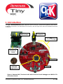
1 Introduction
This QP™ Development Kit (QDK) describes how to use QP™ event-driven platform with the Renesas R8C processors, the Renesas NC30 compiler, and the High Performance Embedded Workshop
4 (HEW4).
Q_SPY trace
data to host
USB cable
To Host PC
E8
In-Circuit Debugger
TTL-RS-232
transceiver
board
4 User LEDs
R8C Tiny
R5F2125
target device
Switch 1
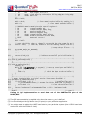
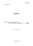
Figure 1 Renesas R8C/Tau board with built-in E8 In-Circuit Debugger and RS232-TTL
transceiver board.
Copyright © Quantum Leaps, LLC. All Rights Reserved.
1 of 26
QDK™
R8C/Tau-NC30
www.state-machine.com/m16c
The actual hardware/software used to validate this QDK is described below (see Figure 1):
1. Renesas R8C/Tau evaluation board with built-in E8 In-Circuit Debugger.
2. High Performance Embedded Workshop 4.04 (HEW4)
3. Renesas NC30 compiler v5.44.
4. QP/C v4.0.01 or higher.
As shown in Figure 1, the Renesas TAU Starter Kit Plus contains the TAU board and the E8 InCircuit Debugger that connects directly to the host development workstation via the provided USB
cable. The USB connection also powers up the board, so no additional power is required. This QDK
has been tested with the R8C Tiny M3026FA8 device with 2KB of RAM and 32KB of onboard flash.
However, the described port should be applicable to even the smallest R8C Tiny devices.
1.1 What’s Included in the QDK?
This QDK provides the QP port to R8C with the Renesas HEW4 IDE and NC30 compiler, the Board
Support Package (BSP) and two versions of the Dining Philosopher Problem (DPP) example application described in the Application Note “Dining Philosopher Problem” [QL AN-DPP 08].
1. DPP with the cooperative “Vanilla” kernel; and
2. DPP with the preemptive run-to-completion QK kernel.
1.2 Licensing QP
The Generally Available (GA) distribution of QP™ available for download from the www.statemachine.com/downloads website is offered with the following two licensing options:
•
The GNU General Public License version 2 (GPL) as published by the Free
Software Foundation and appearing in the file GPL.TXT included in the packaging of every Quantum Leaps software distribution. The GPL open source license allows you to use the software at no charge under the condition that if
you redistribute the original software or applications derived from it, the complete source code for your application must be also available under the conditions of the GPL (GPL Section 2[b]).
•
One of several Quantum Leaps commercial licenses, which are designed for customers who
wish to retain the proprietary status of their code and therefore cannot use the GNU General
Public License. The customers who license Quantum Leaps software under the commercial licenses do not use the software under the GPL and therefore are not subject to any of its terms.
For more information, please visit the licensing section of our website at: www.statemachine.com/licensing
Copyright © Quantum Leaps, LLC. All Rights Reserved.
2 of 26
QDK™
R8C/Tau-NC30
www.state-machine.com/m16c
2 Getting Started
This section describes how to install, build, and use the QDK-R8C-NC30_TAU based two examples.
This information is intentionally included early in this document, so that you could start using the
QDK as soon as possible. The main focus of this section is to walk you quickly through the main
points without slowing you down with full-blown detail.
NOTE: This QDK assumes that the standard QP distribution consisting of QEP, QF, QK, and QS
has been installed, before installing this QDK. It is also strongly recommended that you read
the QP Tutorial (www.quantum-leaps.com/doxygen/qpc/tutorial_page.html) before you start
experimenting with this QDK.
2.1 Installation
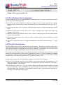
The QDK code is distributed in a ZIP archive (qdkc_r8c-nc30_tau_<ver>.zip, where <ver> stands for
a specific QDK_R8C-NC30_TAU version, such as 4.0.01). You should uncompress the archive into
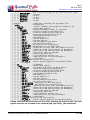
the same directory into which you’ve installed all the standard QP components. The installation directory you choose will be referred henceforth as QP Root Directory <qp>. The following Listing 1
shows the directory structure and selected files included in the QDK distribution. (Please note that
the QP directory structure is described in detail in a separate Application Note: “QP Directory Structure”):
<qp>\
|
+-include/
| +-qassert.h
| +-qep.h
| +-qf.h
| +-qk.h
| +-qequeue.h
| +-qmpool.h
| +-qvanilla.h
|
+-ports\
| +-m16c\
| | +-vanilla\
| | | +-nc30\
| | | | +-dbg\
| | | | | +-qep_r8c.lib
| | | | | +-qf_r8c.lib
| | | | +-dbg\
| | | | +-spy\
| | | | |
| | | | +-make_r8c.bat
| | | | +-qep_port.h
| | | | +-qf_port.h
| | | | +-qs_port.h
| | | | +-qp_port.h
| | |
| | +-qk\
| | | +-nc30\
| | | | +-dbg\
| | | | | +-qep_r8c.lib
| | | | | +-qf_r8c.lib
| | | | | +-qk_r8c.lib
| | | | +-dbg\
| | | | +-spy\
- QP-root directory for Quantum Platform (QP)
–
–
–
–
–
–
-
QP public include files
Quantum Assertions platform-independent public include
QEP platform-independent public include
QF platform-independent public include
QK platform-independent public include
native QF event queue include
native QF memory pool include
native QF cooperative “Vanilla” kernel
-
QP ports
M16C/R8C port
“vanilla” ports
Renesas NC30 compiler
QP libraries – Debug configuration
QEP library for R8C target
QF library for R8C target
QP libraries – Release configuration
QP libraries – Spy configuration
-
make script for building the QP libraries for R8C target
QEP port
QF port
QS port
QP port
-
QK (Quantum Kernel) ports
Renesas NC30 compiler
QP libraries – Debug configuration
QEP library for R8C target
QF library for R8C target
QK library for R8C target
QP libraries – Release configuration
QP libraries – Spy configuration
Copyright © Quantum Leaps, LLC. All Rights Reserved.
3 of 26
QDK™
R8C/Tau-NC30
www.state-machine.com/m16c
| | | | +-make_r8c.bat - make script for building the QP libraries for R8C target
| | | | +-qep_port.h
- QEP port
| | | | +-qf_port.h
- QF port
| | | | +-qk_port.h
- QK port
| | | | +-qs_port.h
- QS port
| | | | +-qp_port.h
- QP port
|
+-examples\
- subdirectory containing the QP example files
| +-m16c\
- M16C/R8C port
| | +-vanilla\
- “vanilla” examples (non-preemptive scheduler of QF)
| | | +-nc30\
- Renesas NC30 compiler
| | | | +-dpp_tau\
- Dining Philosophers example for TAU board
| | | | | +-Debug\
- directory containing the Debug build
| | | | | +-Release\
- directory containing the Release build
| | | | | +-Spy\
- directory containing the Spy build
| | | | | +-bsp.c
- Board Support Package for TAU
| | | | | +-bsp.h
- BSP header file
| | | | | +-dpp.h
- the DPP header file
| | | | | +-main.c
- the main function
| | | | | +-philo.c
- the Philosopher active object
| | | | | +-table.c
- the Table active object
| | | | | +-dpp_tau.hwp – HEW project for this application
| | | | | +-dpp_tau.hws – HEW workspace for this application
| | | | | +-cstartdef.h – definitions of stack, heap, and standard I/O sizes
| | | | | +-firm.c
– definition of ROM section used by the ROM-Monitor
| | | | | +-firm_ram.c
– definition of RAM section used by the ROM-Monitor
| | | | | +-fvector.c
– fixed vector table for M16C/R8C
| | | | | +-heap.c
– heap section definition
| | | | | +-initsct.c
– initialization of sections in C
| | | | | +-intprg.c
– dummy definitions of interrupt handlers
| | | | | +-resetprog.c – reset handler
| | | | | +-taudef.h – Definitions for the TAU board
| | | | | +-sfr_r825.h
– Special Function Registers for the R8C/25 device
| | |
| | +-qk\
- QK examples
| | | +-nc30\
- Renesas NC30 compiler
| | | | +-dpp_qk_tau\
- DPP example with QK for TAU board with QK
| | | | | +-Debug\
- directory containing the Debug build
| | | | | +-Release\
- directory containing the Release build
| | | | | +-Spy\
- directory containing the Spy build
| | | | | +-bsp.c
- Board Support Package for TAU
| | | | | +-bsp.h
- BSP header file
| | | | | +-dpp.h
- the DPP header file
| | | | | +-main.c
- the main function
| | | | | +-philo.c
- the Philosopher active object
| | | | | +-table.c
- the Table active object
| | | | | +-dpp_qk_tau.hwp – HEW project for this application
| | | | | +-dpp_qk_tau.hws – HEW workspace for this application
| | | | | +-cstartdef.h – definitions of stack, heap, and standard I/O sizes
| | | | | +-firm.c
– definition of ROM section used by the ROM-Monitor
| | | | | +-firm_ram.c
– definition of RAM section used by the ROM-Monitor
| | | | | +-fvector.c
– fixed vector table for M16C/R8C
| | | | | +-heap.c
– heap section definition
| | | | | +-initsct.c
– initialization of sections in C
| | | | | +-intprg.c
– dummy definitions of interrupt handlers
| | | | | +-resetprog.c – reset handler
| | | | | +-taudef.h – Definitions for the TAU board
| | | | | +-sfr_r825.h
– Special Function Registers for the R8C/25 device
Listing 1 Selected QP directories and files after installing QP and this QDK. The highlighted elements are included in the standard QDK_R8C-NC30_TAU distribution.
Copyright © Quantum Leaps, LLC. All Rights Reserved.
4 of 26
QDK™
R8C/Tau-NC30
www.state-machine.com/m16c
2.2 Building the QP Libraries
All QP components are deployed as libraries that you statically link to your application. The pre-All
QP components are deployed as libraries that you statically link to your application. The pre-built
libraries for QEP, QF, QS, and QK are provided inside the <qp>\ports\m16c\ directory (see Listing
1). This section describes steps you need to take to rebuild the libraries yourself.
NOTE: To streamline and simplify the QP-library build process, Quantum Leaps software does
not use the vendor-specific IDEs, such as the IAR Embedded Workbench IDE, for building the
QP libraries. Instead, this QDK provides command-line build process based on simple batch
scripts.
The build process for your application is largely independent on the QP-library builds. In fact,
once you have the QP libraries, you typically don’t need to rebuild them—at least not on the
daily basis as you work on your application. This QDK uses the Renesas NC30 compiler to build
the example applications, but you are free to use any other build strategy.
The code distribution contains all the batch file make_r8c.bat for building all the libraries located in
<qp>\ports\m16c\vanilla\nc30\ directory. For example, to build the debug version of all the QP libraries for the M16C, with the NC30 compiler, you open a console window on a Windows PC,
change directory to <qp>\ports\m16c\vanilla\nc30\, and invoke the batch by typing at the command prompt the following command:
make_r8c
The make process should produce the QP libraries in the location: <qp>\ports\m16c\vanilla\nc30\dbg\. The make_r8c.bat assumes that the NC30 toolset has been installed in the directory
C:\tools\Renesas\Hew\Tools\Renesas\nc30wa\v544r00.
NOTE: You need to adjust the symbol RENESAS_M16C_DIR at the top of the make_r8c.bat file if
you’ve installed the NC30 in a different directory.
In order to take advantage of the Q-SPY instrumentation, you need to build the Spy version of the
QP libraries. You achieve this by invoking the make_r8c.bat utility with the “spy” target, like this:
make_r8c spy
The make process should produce the QP libraries in the directory: <qp>\ports\m16c\vanilla\nc30\spy\.
You choose the build configuration by providing a target to the make_r8c.bat utility. The default target is “dbg”. Other targets are “rel”, and “spy” respectively. The following table summarizes the
targets accepted by make_r8c.bat.
Software Version
Build command
Debug (default)
make_r8c
Release
make_r8c rel
Spy
make_r8c spy
Table 1 Supported build configurations for the Debug, Release, and Spy versions
Copyright © Quantum Leaps, LLC. All Rights Reserved.
5 of 26
QDK™
R8C/Tau-NC30
www.state-machine.com/m16c
2.3 Building the Examples
The examples included in this QDK are based on the standard Dining Philosopher Problem application implemented with active objects (see Quantum Leaps Application Note: “Dining Philosopher
Problem Application” [QL AN-DPP 08] includes in this QDK).
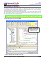
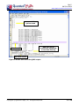
The example directory contains the HEW workspace file dpp_tau.hws that you can load into the HEW
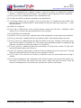
IDE. The workspace contains two build configurations (Debug, Release, and Spy) that you can select with the drop-down list, as shown in Figure 2.
NOTE: The DPP example workspace comes with three build configurations: Debug, Release,
and Spy. You select the build configuration through the drop-down list, as shown in Figure 2.
2.3.1 Loading the Project into HEW
Use the drop-down list
to select one of the build
configurations: Debug,
Release, or Spy
Figure 2 HEW IDE with the dpp_tau project.
Copyright © Quantum Leaps, LLC. All Rights Reserved.
6 of 26
QDK™
R8C/Tau-NC30
www.state-machine.com/m16c
1. Connect the E8 debugger to the TAU board with the provided ribbon cable as described in the
Quick Start Guide.
2. Connect the E8 debugger to the PC with the provided USB cable as described in the Quick Start
Guide.
3. Launch HEW IDE and open the project pelican-tau.hws (located in <qp>\examples\m16c\vanilla\nc30\dpp_tau\). Figure 2 shows the screen shot of the HEW IDE after opening the project.
4. Build the project by select Build->Build menu or by pressing F7.
2.4 Running the Examples
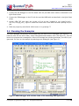
The HEW debugger can directly communicate with the E8 In-Circuit Debugger (see Figure 1). To
load the code into the MCU’s flash, select Debug|Download Modules menu (see Figure 2). This will
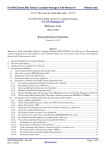
launch the progress-bar message box. When the message box window goes away, the MCU is programmed. You can run the example by selecting menu Debug|Go (see Figure 3).
Figure 3 HEW Debugger with various views of the executing DPP application.
Copyright © Quantum Leaps, LLC. All Rights Reserved.
7 of 26
QDK™
R8C/Tau-NC30
www.state-machine.com/m16c
An example run of the DPP application is shown in Figure 1. The three user LEDs should start blinking. The LEDs represent Philosophers 0-2. An LED-on represents an “eating” philosopher. Extinguished LED represents philosopher “thinking” or “hungry”.
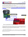
For the QS (Q-SPY) software tracing output, you need to connect a TTL to RS-232 transceiver to
the TAU board, as shown in Figure 4. The figure shows the RS232 to TTL converter board 3.3V
to 5V from NKC Electronics (http://www.nkcelectronics.com/rs232-to-ttl-converter-board33v232335.html), but you can use any other equivalent board.
RS232 to TTL board
TAU board
RX
TX
GND
VCC
Figure 4 Connecting RS232-TTL board to the TAU board.
To see the QS software trace output, you also need to download the Spy build configuration to the
target board. Next you need to launch the QSPY host utility to observe the output in the humanreadable format. You launch the QSPY utility on a Windows PC as follows: (1) Change the directory
to the QSPY host utility <qp>\tools\qspy\win32\mingw\rel and execute:
qspy –c COM2 –b 115200 –O2 –F2
This will start the QSPY host application to listen on COM2 serial port with baud rate 115200.
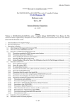
(Please use the actual virtual COM port number on your PC.) The screen shot in Figure 5 shows the
QSPY output from the DPP run:
Copyright © Quantum Leaps, LLC. All Rights Reserved.
8 of 26
QDK™
R8C/Tau-NC30
www.state-machine.com/m16c
command-line
options used
timestamp
data lost due to
insufficient bandwidth
or too little filtering
QS trace record
Figure 5 Screen shot from the QSPY output.
Copyright © Quantum Leaps, LLC. All Rights Reserved.
9 of 26
QDK™
R8C/Tau-NC30
www.state-machine.com/m16c
3 The Vanilla QP Port
The “vanilla” port shows how to use QP on a “bare metal” M16C/R8C-based system without any
underlying multitasking kernel. In the “vanilla” version of the QP, the only component requiring
platform-specific porting is the QF. The other two components: QEP and QS require merely recompilation and will not be discussed here. Obviously, with the vanilla port you’re not using the QK
component. In case of M16C/R8C, the “vanilla” QF port is very similar to the generic “vanilla” port
described in Chapter 9 of [PSiCC2].
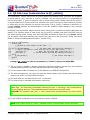
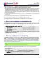
3.1 The qep_port.h Header File
The QEP header file for the M16C/R8C port with the NC30 compiler is located in <qp>\ports\m16c\vanilla\nc30\qep_port.h.
#define QP_SIGNAL_SIZE
/* 1-byte signal space (255 signals) */
1
/* exact-width integer types (NC30 compiler does NOT provide <stdint.h>) */
typedef unsigned char uint8_t;
typedef signed
char int8_t;
typedef unsigned short uint16_t;
typedef signed
short int16_t;
typedef unsigned long uint32_t;
typedef signed
long int32_t;
#include "qep.h"
/* QEP platform-independent public interface */
Listing 2 The qep_port.h header file
The event signal size QP_SIGNAL_SIZE is configured to use 1-byte (256 signals). The next good
choice for M16C/R8C is a 2-byte signal (64K signals). The Renesas NC30 compiler is a pre C99standard compiler and does not provide the exact-width integer types header file <stdint.h> (see
C99 Standard, Section 7.18.1.1). For such a compiler, the standard types are defined using the
typedef directives.
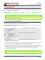
3.2 The qf_port.h Header File
The QF header file for the Cortex-M3 port with the IAR compiler is located in <qp>\ports\cortexm3\vanilla\iar\qf_port.h. The following sub-sections focus on explaining the QF configuration established by the qf_port.h header file shown in Listing 3.
(1)
(2)
(3)
(4)
(5)
(6)
#define
#define
#define
#define
#define
#define
/* various QF object sizes configuration for this port, see NOTE01 */
QF_MAX_ACTIVE
8
QF_EVENT_SIZ_SIZE
2
QF_EQUEUE_CTR_SIZE
1
QF_MPOOL_SIZ_SIZE
2
QF_MPOOL_CTR_SIZE
2
QF_TIMEEVT_CTR_SIZE
2
/* QF critical section entry/exit */
(7) /* QF_INT_KEY_TYPE not defined, see NOTE01 */
(8) #define QF_INT_LOCK(key_)
_asm("FCLR I")
(9) #define QF_INT_UNLOCK(key_)
_asm("FSET I")
Copyright © Quantum Leaps, LLC. All Rights Reserved.
10 of 26
QDK™
R8C/Tau-NC30
www.state-machine.com/m16c
#include "qep_port.h"
#include "qvanilla.h"
#include "qf.h"
/* QEP port */
/* "Vanilla" cooperative kernel */
/* QF platform-independent public interface */
Listing 3 The qf_port.h header file.
3.2.1 The QF Object Size Configuration
The first part of the qf_port.h header file defines limits and sizes of various internal data structures
used in the QF and the applications.
Listing 3(1) QF_MAX_ACTIVE defines the maximum number of active objects that QF can manage.
Here this limit is set to just 8, to save some RAM, but you can increase this limit up to 63, inclusive.
(2) Maximum event size is set to 2-bytes, meaning that the size of a single event can be up to 64K
bytes.
(3) Maximum event queue counter size is set to 1-byte, meaning that a single event queue can
hold up to 255 events.
(4) Maximum memory pool element size is set to 2-bytes, meaning that a pool can mange blocks
of up to 64K bytes each.
(5) The memory pool counter size is set to 2-bytes, meaning that a pool can manage up to 64K
memory blocks.
(6) The timer counter size is set to 2-bytes, meaning that a maximum timeout can be 216-1 clock
ticks.
3.2.2 The QF Critical Section
The M16C/R8C microcontroller supports interrupt prioritization. Therefore it is safe to unlock interrupts inside ISRs without running the risk of priority inversions for interrupts. You have full control
over interrupt nesting by configuring the priorities to interrupts. In particular, you can entirely prevent interrupt nesting by assigning the same priority level to all interrupts.
This means that the simple policy of unconditional unlocking of interrupts upon exit from a critical
section can be used because critical section nesting can be easily and safely avoided (see Chapter
7 of [PSiCC2]). This policy means that you must unlock interrupts inside every ISR before invoking
any QF service, such as QActive_postFIFIO(), QF_publish(), or QF_tick().
The QF critical section policy for M16C/R8C is defined in Listing 3(7-9) as follows:
Listing 3(7) The interrupt lock key is not defined, which means that the interrupt status is not
saved and restored. Just the simple policy of unconditional interrupt locking and unlocking is
used (see Chapter 7 of [PSiCC2]).
(8-9) The macros QF_INT_LOCK() / QF_INT_UNLOCK() define the CPU and compiler-specific interrupt
locking mechanism. For the M16C/R8C, the inline assembly instruction FCLR I clears the global
interrupt enable flag. Conversely, the assembly instruction FSET I sets the global interrupt enable flag in the M16C/R8C flags register.
Copyright © Quantum Leaps, LLC. All Rights Reserved.
11 of 26
QDK™
R8C/Tau-NC30
www.state-machine.com/m16c
3.3 ISRs in the Non-preemptive “Vanilla” Configuration
The NC30 compiler supports writing interrupts in C. In the “vanilla” port, the ISRs are identical as
in the simplest of all “superloop” (main+ISRs), and there is nothing QP-specific in the structure of
the ISRs.
(1) #pragma interrupt timer_re_isr (vect = 10)
(2) void timer_re_isr(void) {
(3)
QF_INT_UNLOCK();
/* Timer RE ISR */
/* see NOTE01 */
(4)
/* clear any level-sensitive interrupt sources, if necessary ... */
(5)
QF_tick();
/* perform other work of the ISR. . . */
(6)
}
QF_INT_LOCK();
/* see NOTE01 */
Listing 4 Time tick interrupt calling QF_tick() function to manage armed time events.
(1) The ISR in C is always compiler-specific, as the C standard does not define how to specify ISRs.
In the case of the NC30 compiler for M16C/R8C interrupt must be declared with the #pragma INTERRUPT. You also need to specify the interrupt vector number in the parentheses as shown.
(2) The ISR in C that follows the interrupt vector specification must have a void (void) signature.
(3) The macro QF_INT_UNLOCK() must be called before invoking any QF services.
NOTE: You should be careful not to introduce nesting of critical sections by leaving interrupts
disabled interrupts before calling any QF services, such as QF_publish() or QF_tick(). In every
ISR you write, you should use the pair of macros QF_INT_UNLOCK() at the beginning and
QF_INT_LOCK() at the end of an ISR.
If you don’t wish an interrupt to be preempted by another interrupt, you can always prioritize
that interrupt to a higher level.
(4) The level-sensitive interrupt sources should be cleared right at the beginning of the ISR. Because the M16C/R8C CPU prioritizes interrupts in hardware, it really does not matter at which
point during the ISR processing the interrupt source is cleared. Even though the interrupts are
unlocked at line (3), the CPU will not allow the same interrupt preempt itself.
(5) The time-tick ISR must invoke QF_tick(), and can also perform other things, if necessary. The
function QF_tick() cannot be reentered, that is, it necessarily must run to completion and return before it can be called again. This requirement is automatically fulfilled, because the
M16C/R8C hardware performs interrupt prioritization and will not allow the same interrupt to
preempt currently running interrupt.
(6) The macro QF_INT_UNLOCK() must be called before returning from the interrupt.
Copyright © Quantum Leaps, LLC. All Rights Reserved.
12 of 26
QDK™
R8C/Tau-NC30
www.state-machine.com/m16c
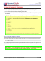
3.4 QP Idle Loop Customization in QF_onIdle()
The cooperative “vanilla” kernel can very easily detect the situation when no events are available,
in which case QF_run() calls the QF_onIdle() callback. You can use QF_onIdle() to suspended the
CPU to save power, if your CPU supports such a power-saving mode. Please note that QF_onIdle()
is called repetitively from the event loop whenever the event loop has no more events to process,
in which case only an interrupt can provide new events. The QF_onIdle() callback is called with interrupts locked, because the determination of the idle condition might change by any interrupt
posting an event.
M16C/R8C microcontrollers support several power-saving levels (consult the specific data sheet for
details). The following piece of code shows the QF_onIdle() callback that puts M16C/R8C into the
idle power-saving mode. Please note that M16C/R8C architecture allows for very atomic setting
the low-power mode and enabling interrupts at the same time (see the article “Using Low-Power
Modes in Foreground/Background Systems” [Samek 07a]).
(1) void QF_onIdle(void) {
#ifdef Q_SPY
/* perform QS trace output via R8C UART... */
. . .
(2) #elif (defined NDEBUG)
/* low-power mode interferes with debugging
(3)
/* stop all peripheral clocks that you can in your applicaiton ... */
(4)
_asm("FSET I");
/* NOTE: the following WAIT instruction will
(5)
_asm("WAIT");
/* execute before entering any pending interrupt
#else
(6)
QF_INT_UNLOCK();
/* just unlock interrupts
#endif
}
*/
*/
*/
*/
Listing 5 QF_onIdle() for the non-preemptive (“vanilla”) QP port to M16C/R8C.
(1) The QF_onIdle() callback is always called with interrupts locked to prevent any race condition
between posting events from ISRs and transitioning to the sleep mode.
(2) The low-power mode is entered only in the Release (not DEBUG) configuration.
(3) The clock management registers are setup the desired sleep mode. Please note that the sleep
mode is not active until the SLEEP command.
(4) The interrupts are unlocked with the FSET I instruction.
(5) The sleep mode is activated with the WAIT instruction.
NOTE: As described in “M16C/60, M16C/20 Series Software Manual”, Section 5.2.1 “Interrupt
Enable Flag”, the instruction immediately following the FSET I instruction, will be executed before any pending interrupt. This guarantees atomic transition to the WAIT mode.
CAUTION: The instruction pair (FSET I, WAIT) should never be separated by any other instruction.
(6) In the DEBUG configuration the interrupts are simply unlocked.
NOTE: Every path through QF_onIdle() callback function must ultimately unlock interrupts.
Copyright © Quantum Leaps, LLC. All Rights Reserved.
13 of 26
QDK™
R8C/Tau-NC30
www.state-machine.com/m16c
4 The QK Port
The QP port with the preemptive kernel (QK) is remarkably simple and very similar to the “vanilla”
port. In particular, the interrupt locking/unlocking policy is the same, and the BSP is identical, except some small additions to the ISRs.
The DPP example for the QK port is provided in the directory <qp>\examples\m16c\qk\nc30\dpp_qk_tau.
NOTE: QK incurs far less overhead and provides responsiveness exceeding that of any traditional multiple-stack real-time kernel, at the fraction of the RAM/ROM footprint (see the article
“Build a Super Simple Tasker”, [Samek+ 06]). The non-blocking restrictions of this kernel type
are irrelevant for executing state machines.
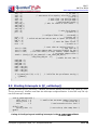
4.1 The qk_port.h Header File
In the QK port, you use very similar configuration as the “Vanilla” port described earlier. This section describes only the differences, specific to the QK component.
You configure and customize QK through the header file qk_port.h, which is located in the QP ports
directory <qp>\ports\m16c\qk\nc30\.
/* interrupt entry code, see NOTE01 */
(1) #define QK_ISR_ENTRY() do { \
(2)
++QK_intNest_; \
(3)
_asm("FSET I"); \
} while (0)
/* interrupt exit code, see NOTE01 and NOTE02 */
(4) #define QK_ISR_EXIT() do { \
(5)
_asm("LDC #0,FLG"); \
(6)
--QK_intNest_; \
(7)
if (QK_intNest_ == (uint8_t)0) { \
(8)
QK_schedule_(); \
} \
} while (0)
(9) #include "qk.h"
/* QK platform-independent public interface */
Listing 6 qk_porth.h header file
(1) The macro QK_ISR_ENTRY() is designed to be called upon the entry to an ISR programmed in C.
The macro informs the QK preemptive kernel about entering an interrupt.
(2) The QK interrupt nesting up-down counter QK_intNest_ is incremented to account for entering a
new interrupt level. This informs the QK scheduler about the interrupt context, so that if a QF
API is called or another interrupt preempts this one, the QK scheduler will not be called.
(3) The interrupts are unlocked.
NOTE: The hardware interrupt entry sequence for M16C/R8C includes clearing the global interrupt enable flag in the FLAGS register, so that interrupts remain locked unless unlocked explicitly.
Copyright © Quantum Leaps, LLC. All Rights Reserved.
14 of 26
QDK™
R8C/Tau-NC30
www.state-machine.com/m16c
(4) The macro QK_ISR_EXIT() is designed to be called upon the exit from an ISR programmed in C.
The macro informs the QK preemptive kernel about exiting an interrupt.
(5) The flags register is set to zero, which accomplishes two things at the same time. First, the interrupts are locked again (the I flag is cleared). Second, the current interrupt priority level (IPL)
of the M16C/R8C processor is forced to zero, which corresponds to the task-level priority. Setting the IPL to zero enables all interrupts and is effectively the End-Of-Interrupt instruction for
the M16C/R8C architecture.
(6) The QK interrupt nesting up-down counter QK_intNest_ is decremented to the level before entering the ISR.
(7) Only if the interrupt nesting drops to zero (ISR nested on task-level code)…
(8) The QK scheduler is called to perform the asynchronous preemptions.
(9) The QK configuration is specified simply by including the ”qk.h” QK interface.
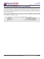
4.2 ISRs in the Preemptive Configuration with QK
As all preemptive kernels, QK must be notified about interrupt entry and exit. You achieve this by
means of the QK macros QK_ISR_ENTRY() and QK_ISR_EXIT(), as shown in Listing 7.
#pragma interrupt timer_re_isr (vect = 10)
void timer_re_isr(void) {
/* Timer
QK_ISR_ENTRY();
/* inform QK about entering
QF_tick();
/* process all armed time
/* perform other ISR work . . . */
QK_ISR_EXIT();
/* inform QK about exiting
}
RE ISR */
in ISR */
events */
in ISR */
Listing 7 Time tick interrupt calling QF_tick() function to manage armed time events
and QK ISR entry/exit macros.
4.3 Idle Loop Customization in the QK Port
As described in Chapter 10 of [PSiCC2], the QK idle loop executes only when there are no events to
process. The QK kernel allows you to customize the idle loop processing by means of the callback
QK_onIdle(), which is invoked by every pass through the QK idle loop. You can define the platformspecific callback function QK_onIdle() to save CPU power, or perform any other “idle” processing
(such as Quantum Spy software trace output).
NOTE: The idle callback QK_onIdle() is invoked with interrupts unlocked (which is in contrast to
QF_onIdle() that is invoked with interrupts locked, see Section ).
The following Listing 8 shows an example implementation of QK_onIdle() for the M16C/R8C.
void QK_onIdle(void) {
#ifdef Q_SPY
/* perform QS trace output via R8UART */
#elif (defined NDEBUG)
/* low-power mode interferes with debugging */
/* stop all peripheral clocks that you can in your applicaiton ... */
_asm("WAIT");
/* execute before entering any pending interrupt */
#endif
Copyright © Quantum Leaps, LLC. All Rights Reserved.
15 of 26
QDK™
R8C/Tau-NC30
www.state-machine.com/m16c
}
Listing 8 QK_onIdle() callback for R8C
Copyright © Quantum Leaps, LLC. All Rights Reserved.
16 of 26
QDK™
R8C/Tau-NC30
www.state-machine.com/m16c
5 Board Support Package
The Board Support Package (BSP) for R8with the non-preemptive Vanilla kernel is located in the
directory: <qp>\examples\m16c\vanilla\nc30\dpp_tau\ and consists of the following files:
1. bsp.h contains the Board Support Package interface (BSP)
2. bsp.c contains the implementation of the BSP, which includes all ISRs and all platform-specific
QP callbacks.
NOTE: This QDK uses the recommended by Renesas C-startup for M16C/R8C. The C-startup
code is comprised of the following files (see also Listing 1):
1. cstartdef.h – stack and heap size definitions (customize for your application)
2. firm.c
3. firm_ram.c
4. fvector.c
5. heap.c
6. initsct.c
7. initsct.h
8. intprg.c – default interrupt handlers (customize for your application)
9. resetprg.c
10. resetprg.h
Out of these 10 files only the indicated 2 files need customization for a specific application.
5.1 Compiler Options Used
You set the compiler and linker options through the HEW IDE. The compiler options are as follows:
-c -g -Wall -silent
The –g option denotes that the compiler should generate the Debug information. This option is only
used in the Debug build. Both the Debug and Release builds use the generic CPU type “With no
specification”.
NOTE: You can access the compiler options by selecting the Build->Renesas M16C/R8C Standard Toolchain..., or by right-clicking on any of the C modules in the Workspace window and
choosing the Build Options/Renesas M16C/R8C Standard Toolchain... pop-up menu.
Copyright © Quantum Leaps, LLC. All Rights Reserved.
17 of 26
QDK™
R8C/Tau-NC30
www.state-machine.com/m16c
5.2 Linker Options Used
5.2.1 Specifying Program Sections
The HEW IDE allows to specify very precisely all the program sections, as shown in the screen shot
in Figure 6. For the TAU board, the sections are configured according to the memory map included
in Section 6.3 of the “TAU User’s Manual” [Renesas TAU].
4. Specify sections
according to the
memory map in
the RSKM16C26A
User’s Manual
1. Select
Link Tab
2. Select
Section Order
category
3. Press
Edit
FirmRam_NE section
for “Kernel RAM”
FirmArea_FE section
for “Kernel Program”
Figure 6 Specifying the sections names and addresses in the HEW IDE.
In particular, the Section Order dialog box shows the special RAM section FirmRAM_NE for the
“Emulator Firmware RAM” located at 0x0B80 and the ROM section FirmArea_FE for “Emulator
Firmware Area” at 0x8000. “Emulator Firmware” in the Renesas terminology means ROM-monitor
resident in the target and communicating with the HEW debugger via the E8 In-Circuit Debugger.
NOTE: The location of the “Emulator Firmware Area” (section FirmArea_NE) can be configured
via the HEW IDE. The Debug Session SessionR8C_E8_SYSTEM used in this QDK-nano configures
the location of the “Emulator Firmware Area” to 0x8000, which is consistent with section order
shown in Figure 6.
Copyright © Quantum Leaps, LLC. All Rights Reserved.
18 of 26
QDK™
R8C/Tau-NC30
www.state-machine.com/m16c
5.2.2 Specifying Stack and Heap Sizes
This QDK-M16C/R8C does not use the heap 1 uses only the Interrupt Stack and no User Stack.
Therefore, you disable the heap and set the User Stack size to zero. You need to declare adequate
stack size for the Interrupt Stack, which is the only stack used in this QDK-nano. In the C-startup
code, you specify the heap and stack sizes in the file cstartdef.h:
/* Modify the next line if you change the stack size */
#define __STACKSIZE__
0x0
/* Modify the next line if you change the interrupt stack size */
#define __ISTACKSIZE__
0x80
/* Modify the next line if you change the heap size */
#define __HEAPSIZE__
0x0
/* Modify the next line if you change the standard I/O */
#define __STANDARD_IO__ 0
NOTE: The QK preemptive kernel generally requires more stack space than the cooperative
“Vanilla” kernel. You need to adjust the __ISTACKSIZE__ value for your system.
5.3 The BSP header file bsp.h
(1) #include "sfr_r825.h"
(2) #include "taudef.h"
/* RSK-R8C25 board */
/*--------------------------------------------------------------------------*/
(3) #define BSP_TICKS_PER_SEC
50
/*..........................................................................*/
void BSP_init(void);
void BSP_displyPhilStat(uint8_t n, char const *stat);
Listing 9 The bsp.h for the PELICAN crossing example.
(1) The header file “sfr_r825.h” provides the definitions of the R8C/25 special function registers.
(2) The header file “taudef.h” defines the interface to the TAU board.
(3) The BSP defines the desired ticking rate. This constant is useful for defining timeouts, which are
always specified in units of clock ticks.
5.4 BSP initialization
The following BSP_init() function from the PELICAN crossing application for the TAU board configures the PIO lines for the User LEDs, the system clock tick, and the QS output:
void BSP_init(void) {
prcr = 1;
/* initialize the CPU clock... */
/* protect off */
1
Using the heap in real-time embedded devices can cause many problems, such as heap fragmentation, nondeterminism, concurrency issues, etc.
Copyright © Quantum Leaps, LLC. All Rights Reserved.
19 of 26
QDK™
R8C/Tau-NC30
www.state-machine.com/m16c
cm13 = 1;
cm15 = 1;
cm05 = 0;
cm16 = 0;
cm17 = 0;
cm06 = 0;
asm("nop");
asm("nop");
asm("nop");
asm("nop");
ocd2 = 0;
prcr = 0;
/* Xin Xout
/* XCIN-XCOUT drive capacity select bit : HIGH
/* Xin on
/* main clock = No division mode
/* main clock = No division mode
/* CM16 and CM17 enable
/* Wait for stable of oscillation...
*/
*/
*/
*/
*/
*/
*/
/* main clock change */
/* protect on */
/* configure 32kHz clock..., see NOTE02
/* protect off
/* unlock CM0 and CM1 and set GPIO to inputs (XCin/XCout)
/* ...
/* Start the 32KHz crystal
/* protect on
*/
*/
*/
*/
*/
*/
/* start Timer RE running from fc4...
/* stop Timer RE
/* output compare mode, interrupt disabled for now
/* fc4 clock source, no 4-bit counter, output compare
/* set output compare value
tremin = (uint8_t)((fc_CLK_SPEED/4/2 + BSP_TICKS_PER_SEC/2)
/ BSP_TICKS_PER_SEC - 1);
/* enable the User LEDs
LED0_DDR = 1;
LED1_DDR = 1;
LED2_DDR = 1;
LED3_DDR = 1;
LED0 = LED_OFF;
LED1 = LED_OFF;
LED2 = LED_OFF;
LED3 = LED_OFF;
*/
*/
*/
*/
*/
prc0
pd4_3
pd4_4
cm04
prc0
=
=
=
=
=
1;
0;
0;
1;
0;
trecr1 = 0x00;
trecr2 = 0x00;
trecsr = 0x63;
if (QS_INIT((void *)0) == 0) {
Q_ERROR();
}
*/
/* initialize the QS software tracing */
}
5.5 Starting Interrupts in QF_onStartup()
QP-nano invokes the QF_onStartup() callback just before starting the event loop inside QF_run().
The QF_onStartup() function must start the interrupts configured earlier. In this BSP only the system tick interrupt is started.
void QF_onStartup(void) {
comie_trecr2 = 1;
tstart_trecr1 = 1;
treic
= 3;
#ifdef Q_SPY
tstart0_trdstr = 1;
#endif
}
/* enable Timer RE output compare interrupt */
/* start Timer RE */
/* TRE interrupt priority level */
/* start the QS time-stamp timer */
Listing 10 Configuring and enabling interrupts in the QF_onStartup() callback.
Copyright © Quantum Leaps, LLC. All Rights Reserved.
20 of 26
QDK™
R8C/Tau-NC30
www.state-machine.com/m16c
5.6 Assertion Handling Policy in Q_onAssert()
As described in Chapter 6 of [PSiCC2], all QP components use internally assertions to detect errors
in the way application is using the QP services. You need to define how the application reacts in
case of assertion failure by providing the callback function Q_onAssert(). Typically, you would put
the system in fail-safe state and try to reset. It is also a good idea to log some information as to
where the assertion failed.
The following code fragment shows the Q_onAssert() callback for M16C/R8C. The function simply
locks all interrupts and enters a for-ever loop. This policy is only adequate for testing, but probably
is not adequate for production release.
void Q_onAssert(char const Q_ROM * const Q_ROM_VAR file, int line) {
(void)file;
/* avoid compiler warning
(void)line;
/* avoid compiler warning
QF_INT_LOCK();
/* lock the interrupts
for (;;) {
/* hang in this for-ever loop
}
}
Copyright © Quantum Leaps, LLC. All Rights Reserved.
*/
*/
*/
*/
21 of 26
QDK™
R8C/Tau-NC30
www.state-machine.com/m16c
6 The Quantum Spy (QS) Instrumentation
This QDK demonstrates how to use the QS software tracing instrumentation to generate real-time
trace of a running QP application. Normally, the QS instrumentation is inactive and does not add
any overhead to your application, but you can turn the instrumentation on by defining the Q_SPY
macro and recompiling the code.
QS is a software tracing facility built into all QP components and also available to the Application
code. QS allows you to gain unprecedented visibility into your application by selectively logging almost all interesting events occurring within state machines, the framework, the kernel, and your
application code. QS software tracing is minimally intrusive, offers precise time-stamping, sophisticated runtime filtering of events, and good data compression (see Chapter 11 in PSiCC2 [PSiCC2]).
QS can be configured to send the trace data out of the serial port of the target device. On the
R8C/Tau board, QS uses the built-in UART0 to send the trace data to the host. The QS platformdependent implementation is located in the file bsp.c and looks as follows:
(1) #ifdef Q_SPY
(2)
#define QS_BUF_SIZE
(3)
#define QS_BAUD_RATE
(1*256)
115200
enum AppRecords {
PHILO_STAT = QS_USER
};
(4)
/* application-specific trace records */
/* number of underflows of Timer A1 */
static uint16_t l_nTimerA1Underflows = 1;
(5) uint8_t QS_onStartup(void const *arg) {
(6)
static uint8_t qsBuf[QS_BUF_SIZE];
uint16_t n;
(7)
QS_initBuf(qsBuf, sizeof(qsBuf));
(8)
pd1_4 = 1;
pd1_5 = 0;
/* buffer for Quantum Spy */
/* UART0 configuration */
/* set UART0 TX pin as output */
/* set UART0 RX pin as input */
/* set UART0 bit rate generator... */
/* bit rate can be calculated by:
* bit rate = ((BRG_count_source / 16)/baud_rate) - 1
* the value of BCLK does not affect BRG count source
*/
u0brg = (uint8_t)(((f1_CLK_SPEED/16 + BAUD_RATE/2) / BAUD_RATE) - 1);
/* 00000101 8 bit,
* b2:b0
SMD2:0
* b3
CKDIR
* b4
STPS
* b5
PRY
* b6
PRYE
* b7
*/
u0mr = 0x05;
internal clock, 1 stop, no parity, no inversion
Selects Uart mode, 8 bit data transfer
Internal clock selected
One stop bit
Odd parity (parity is disabled using b6)
Disable parity
Reserved, set to 0
/* 00010000 MSB first, cmos output, CTS/RTS disabled, f1 clock source
*
b1:b0
CLK1:0 Count source divided by 1
*
b2
Reserved, set to 0
*
b3
TXEPT Transmit register empty flag
*
b4
Reserved, set to 0
Copyright © Quantum Leaps, LLC. All Rights Reserved.
22 of 26
QDK™
R8C/Tau-NC30
www.state-machine.com/m16c
*
b5
NCH
*
b6
CKPOL
*
b7
UFORM
*/
u0c0 = 0x00;
u0tb = u0rb;
u0tb = 0;
Data output select bit
Clock polarity selected,TX falling edge,RX rising edge
MSB first
/* clear UART0 receive buffer by reading it */
/* clear UART0 transmit buffer */
/* 00000101 UART0 transmit/receive control register 1
* b0
TE
Transmit Enable Bit
* b1
TI
Transmit buffer empty flag,
* b2
RE
Receive enable bit,
* b3
RI
Receive complete flag,
* b4
U1IRS Transmit buffer empty select,
* b5
U1RRM Disable continous receive mode,
* b6:b7
Reserved, set to 0
*/
u0c1 = 0x05;
(9)
/* start the 16-bit Timer D, channel 1 to provide the time stamp for QS */
trdcr0 = 0x03;
/* Timer RD, channel 0 as free running counter from f8 */
/* setup the QS filters... */
(10)
(11)
(12)
(13)
(14)
(15)
(16)
(17)
(18)
QS_FILTER_ON(QS_ALL_RECORDS);
. . .
. . .
return (uint8_t)1;
/* indicate successfull QS initialization */
}
/*..........................................................................*/
void QS_onCleanup(void) {
}
/*..........................................................................*/
void QS_onFlush(void) {
uint16_t b;
while ((b = QS_getByte()) != QS_EOD) { /* next QS trace byte available? */
while (ti_u0c1 == 0) {
}
U0tb = b;
/* stick the byte to the TX buffer */
}
}
/*..........................................................................*/
/* NOTE: invoked within a critical section (inetrrupts disabled) */
QSTimeCtr QS_onGetTime(void) {
if (ovf_trdsr0 != 0) {
/* overflow flag set? */
++l_nTimerRDunderflows; /* account for 16-bit underflow (0->0xFFFF) */
ovf_trdsr0 = 0;
/* clear the overflow flag */
}
return ((QSTimeCtr)l_nTimerRDunderflows << 16) + (QSTimeCtr)trd0;
}
#endif
/* Q_SPY */
Listing 11 QS implementation to send data out of the UART0serial port of the
M16C/R8C
(1) The QS instrumentation is enabled only when the macro Q_SPY is defined
(2) You should adjust the QS buffer size (in bytes) to your particular application
(3) You might want to adjust the UART baud rate to your particular system (the 115200 baud rate
works well with the 20MHz f1 clock)
Copyright © Quantum Leaps, LLC. All Rights Reserved.
23 of 26
QDK™
R8C/Tau-NC30
www.state-machine.com/m16c
(4) The l_nTimerA1Underflows variable is used to count the number of underflows (transitions
0x0000 -> 0xFFFF) of the 16-bit TimerA1. This variable is used to generate 32-bit timestamp.
(5) The QS_onStartup() callback performs the initialization of QS
(6) The QS trace buffer is statically allocated to the specified size
(7) You always need to call QS_initBuf() from QS_onStartup() to initialize the trace buffer. This
particular QS port initializes UART for data transfer at the given baud rate (BAUD_RATE = 115200
bits per second)
(8) UARTA0 is configured.
(9) Timer RD is configured as a free-running counter running from f8 (f1/8 = 20MHz/8), which
works out to 0.4 µs per the least-significant bit of this counter.
(10) The QS filters are configured.
(11) Return 1 from QS_onStartup() callback means that configuration of QS output was successfull.
(12) The QS_onCleanup() callback performs the cleanup of QS. Here nothing needs to be done.
(13) The QS_onFlush() callback flushes the QS trace buffer to the host. Typically, the function busywaits for the transfer to complete. It is only used in the initialization phase for sending the QS
dictionary records to the host (see Chapter 11 in [PSiCC2])
(14) The QS_getTime() callback provides the time-stamp to the QS trace records. The QS timestamping implementation uses Timer A1.
(15) Here the interrupt request flag is tested to find out whether Timer RD rolled over. This flag
being set means that the timer rolled over from 0x0000 to 0xFFFF.
(16-17) In case of the rollover the number of underflows must be incremented and the flag is
cleared.
(18) The 32-bit timestamp is the combination of the rollover counter (the coarse time) and the current value of the Timer RD counter (the fine time). Please note that the 16-bit Timer RD
counter is subtracted from the coarse time, because the counter counts down.
Copyright © Quantum Leaps, LLC. All Rights Reserved.
24 of 26
QDK™
R8C/Tau-NC30
www.state-machine.com/m16c
7 Related Documents and References
Document
Location
[PSiCC2] “Practical UML Statecharts in
C/C++, Second Edition”, Miro Samek, Newnes, 2008
Available from most online book retailers, such as
amazon.com. See also: http://www.quantumleaps.com/psicc2.htm
[QP 08] “QP/C/C++ Reference Manuals”,
Quantum Leaps, LLC, 2008
http://www.quantum-leaps.com/doxygen/qpc/
[QL AN-Directory 07] “Application Note: QP
Directory Structure”, Quantum Leaps, LLC,
2007
http://www.quantumleaps.com/doc/AN_QP_Directory_Structure.pdf
[QL AN-PELICAN 08] “Application Note: PELICAN Crossing Application”, Quantum Leaps,
LLC, 2008
http://www.quantumleaps.com/doc/AN_PELICAN.pdf
http://www.quantum-leaps.com/doxygen/qpcpp/
[R8C/25 Hw] “R8C/24, R8C/25 Group Hardware Manual”, Renesas 2005
Renesas document REJ09B0244-0010, available
online at www.renesas.com
[M16C Sw] “M16C/60, M16C/20 Series Software Manual”, Renesas, 2003.
Document included in PDF with the TAU Plus kit.
[M16C C-compiler] “M16C/60 M16C/20 Series
<C language> Programming Manual”, Renesas
2003
Document included in PDF with the TAU Plus kit.
[NC30] “NC30 C Compiler for R8C/Tiny,
M16C/60,30,20,10 Series User's Manual”, Renesas 2003
Renesas document REJ10J0225-0100Z, available
online at www.renesas.com
[Renesas TAU] “Renesas Starter Kit for R8C/25
User’s Manual”, Reneas 2006
Renesas document REJ10J1242-0101 included in
PDF with TAU kit.
[Samek 06b] “Build a Super Simple Tasker”,
Embedded Systems Design, Miro Samek and
Robert Ward, July 2006
http://www.embedded.com/shared/printableArticle.jhtml?articleID=190302110
[Samek 07a] “Using Low-Power Modes in Foreground/Background Systems”, Miro Samek, to
be published in ESD, October 2007
www.embedded.com/mag.htm
Copyright © Quantum Leaps, LLC. All Rights Reserved.
25 of 26
QDK™
R8C/Tau-NC30
www.state-machine.com/m16c
8 Contact Information
Quantum Leaps, LLC
103 Cobble Ridge Drive
Chapel Hill, NC 27516
USA
+1 866 450 LEAP (toll free, USA only)
+1 919 869-2998 (FAX)
e-mail: [email protected]
WEB : http://www.quantum-leaps.com
http://www.state-machine.com
“Practical UML
Statecharts in C/C++,
Second Edition: Event
Driven Programming
for Embedded Systems”, by Miro Samek,
Newnes, 2008
Renesas Technology Corp.
2-6-2, Ote-machi Chiyoda-ku,
Tokyo,100-0004
Japan
WEB: www.renesas.com
Copyright © Quantum Leaps, LLC. All Rights Reserved.
26 of 26