1
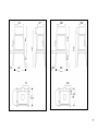
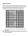
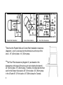
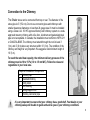
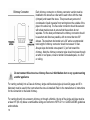
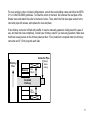
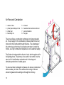
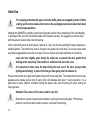
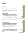
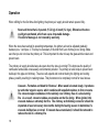
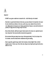
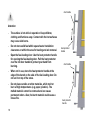
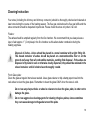
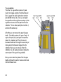
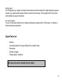
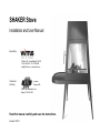
SHAKER Stove Installation and User Manual Imported by: PO Box 120 Pound Ridge NY 10576 T.914-764-5679 F.914-764-0465 info@ Wittus.com www.wittus.com Tested and Listed by: C US Portland Oregon USA OMNI-Test Laboratories, Inc. Report #: 339-S-01-02 Read this manual carefully and save the instructions. Revised 10/13/11 Installation and User Manual Table of Contents Introduction and Purpose Technical Data Service Packet Outside Air Supply Installation of Your Stove Connection to the Chimney Air Flow and Combustion Permitted Fuels Initial Use Heating Up Operation Cleaning Instructions Spare Parts List Maintenance of the Stove Testing and Approvals Warranty Troubleshooting 2 3 4-5 6 6 7-8 9-11 12 13 14 15 16-18 19-21 21 22-23 24 24 25 Introduction and Purpose The purpose of this manual is to guide and instruct Shaker stove owners in proper burning to achieve environmentally friendly combustion and to minimize the risk of incorrect use and operation of the stove. Failure to follow instructions may result in property damage, bodily injury, or even death. It is therefore very important to read this entire manual carefully before you install and use your new Shaker stove, and save the instructions. Correct operation is also vital with regard to our applicable warranty terms. For more information on wood burning visit the website http://woodheat.org/. BEFORE YOU INSTALL YOUR STOVE WE RECOMMEND THAT YOU CONTACT YOUR DEALER OR LOCAL BUILDING INSPECTOR OR FIRE MARSHALL TO HELP YOU FOLLOW THE RULES AND REGULATIONS IN YOUR LOCAL AREA. WE ALSO RECOMMEND THAT YOUR DEALER CHECK THE STOVE BEFORE INSTALLATION FOR COMPLETENESS AND FUNCTIONALITY. If your stove is not installed properly, a home fire may result. To reduce the risk of fire, follow the installation instructions. Contact local building or fire officials about restrictions and installation inspection requirements in your area. Not approved for use in a mobile home. Follow the manual during installation and operating of the stove. Take particular note of this symbol throughout the manual. This indicates special attention. 3 Technical Data SHAKER Stove: Description Data Test data: Safety approval for United States Safety approval for Canada Environmental approval (EPA Certified) Optimal heat output Heat output range (minimum-maximum) Heating capacity range Efficiency Stove height Stove width – short / long bench Stove depth Firebox height Firebox width Firebox depth Door opening area to the fire chamber Weight of stove without a table Weight of the table - long / short Optional venting outlets Diameter of the stove pipe Height to center of pipe – back vent Diameter of the air supply connector Air supply outlet – height at back of stove Cladding on body and table Color UL 1482 ULC S627 7.2 gm/hr emission rate 20kBTU (6kW) 10-23kBTU (3-7kW) 2 2 520-1,330ft (20-50m ) 78% 41” (103,5 cm) 33” (84cm) / 72” (184cm) 21” (53cm) 14” (35cm) 16” (40cm) 13” (32cm) 88in.2 (564 cm2) 247lbs. (112kg) 71lbs. (32kg) / 38lbs. (17kg) top or back vent 6” (15cm) 36” (915mm) 4” (10cm) 19.5” (50cm) to center of opening steel black Heating: Stove dimensions: Firebox dimensions: Area: Weight: Venting: Stove pipe: Outside air supply: Material data: 4 14“ 350 400 16“ 400 36“ 915 25“ 635 16“ 20“ 23“ 265 12“ 505 575 263 460 525 10“ 290 18“ 21“ 10“ 5 Service Packet The SHAKER stove is delivered with a service packet. It contains the installation and user manual, copper lubricant, the heat protector handle, and a glove. Please note that the glove supplied with the stove is equally suitable for left and right-handed persons. Outside Air Supply outside air supply Ensure that there is sufficient combustion air in the room in which the stove is installed, and that there is an adequate supply of combustion air to the stove, which can be supplied from another room or from outside. With the Shaker air system, the stove uses combustion air from either another room or outside (through a connection to the firebox via the outside air connector). Stoves with combustion air supply from outside are particularly suited for rooms with negative pressure (e.g. use of exhaust fan). Please refer to your dealer, as this connection should always be made by a qualified person. 6 Installation of Your Stove The distances (see Fig. on page 8) of the stove to combustible materials or walls are listed in the table below. These are the minimum clearances for installation, and any reductions must first be approved by the regulatory authority. Clearances to noncombustible materials are 2” (5cm), but note that “noncombustible” must be solid cement or block (not brick or tile over combustible material). Fig. Label I. I. II. II. I. I. II. II. III. III. III. A B C1 C2 D E F1 F2 Description Distance to side walls Distance to back wall Corner to side walls – door side Corner to side walls – back side Connector pipe to side walls Connector pipe to back wall Corner pipe to side walls – door side Corner pipe to side walls – back side Fuel-door floor plate protection Side floor plate protection Back floor plate protection Ceiling to top of stove Ceiling to connector pipe Distance to combustibles from glass US Canada inches cm inches cm 15.5 39 15.5 39 12.5 32 12.5 32 14.5 37 14.5 37 12.5 32 12.5 32 21 53 21 53 16 41 16 41 22 56 22 56 20 51 20 51 16 41 18 46 8* 20* 8 20 0 0 8 20 36 92 36 92 18 46 18 46 16 41 18 46 *Beyond the sides of the fuel loading door Use floor plates under the stove made with non-combustible fire-resistant materials such as steel, tile, or glass. Before installation, make sure the floor can carry the weight of the stove (in the Technical data section of this manual). 7 I. - Parallel Wall Installation II. - Corner Wall Installation III. – Floor Plate Clearances * *Note that the Parallel Wall and Corner Wall Installation clearances (diagrams I. and II.) are based on the dimensions at the top of the stove - 16” (40cm) wide x 14” (35cm) deep. **The Floor Plate clearances (diagram III.) are based on the dimensions at the base of the stove unit (not including the bench) 20” (50cm) wide x 18” (46cm) deep. Therefore, the required minimum size for the Shaker floor plate is 36” (91cm) wide x 34” (86cm) deep in the US and 46” (115cm) wide x 34” (86cm) deep for Canada. 8 ** Connection to the Chimney The Shaker stove can be connected from top or rear. The diameter of the stove pipe is 6” (152 cm). Do not use connector pipes and chimneys with smaller clearance diameters or less than 24 gauge steel. It must be installed using a Class A UL 103 HT approved factory-built chimney system or a codeapproved masonry chimney with a flue liner. Aluminum and galvanized steel pipe is not acceptable. In Canada, the installation must conform to NFPA 211 or CAN/CSA-B365. The chimney must extend through the roof at least 3’ (1m), and 2’ (6 m) above any structure within 10’ (3 m). The condition of the chimney and height is very important. We suggest a total minimum height of 10’ (3 m). A B C D B To reach the rated heat capacity, the minimum delivery pressure of the chimney must be 10 to 15 Pa (1.0 to 1.5 mm WC). Follow the rules and regulations in your local area. Required Installation Components A Chimney cap B Insulated chimney C Storm collar D Roof flashing E Ceiling support box F Chimney connector pipe E F It is very important to ensure that your chimney has a good draft. Your dealer or your chimney sweep will be able to guide and advise you on your chimney conditions. 9 Each chimney connector or chimney connector section must be installed to the stove flue collar and to each other with the male (crimped) end toward the stove. This prevents any amount of condensed or liquid creosote from running down the outside of the pipe or the stove top. The flue collar connector should be secured with sheet metal screws to ensure that the sections do not separate. For the best performance the chimney connector should be as short and direct as possible, with no more than two 90° elbows. The maximum horizontal run is 36” and a recommended total length of chimney connector should not exceed 10 feet. Always slope horizontal runs upward ¼” per foot toward the chimney. Note the chimney connector pipe should not pass through an attic or roof space, closet or similar concealed space, or a floor or ceiling. Do not connect this stove to a chimney flue or air distribution duct or any system serving another appliance. For venting vertically into a Class A chimney, single wall black steel pipe (at least 24 gauge and 6” in diameter) must be used in the room where the stove is installed. Refer to the manufacturer´s instructions for the connection to the listed chimney. For venting directly into a masonry chimney or through a thimble, the top of the single wall pipe must be at least 18“ (46 cm) below a combustible ceiling and conform to NFPA 211 or CAN/CSA-B365 guidelines and methods. 10 For rear venting or other not listed configurations, consult the local building codes and follow the NFPA 211 or CAN/CSA-B365 guidelines. To install the collar on the back, first unscrew the rear plate of the Shaker stove and attach the collar to the back of stove. Then, attach the first stove pipe section to the connector pipe with screws, and replace the rear wall plate. If the chimney connector is fitted with a baffle, it must be manually operated, visibly placed for ease of use, and must not close completely. Consult your chimney expert if you have any questions. Make sure that there is easy access to the chimney cleanout door. Floor protection is required under the chimney connector and 2" (51cm) beyond each side. Connector Pipe 18”(46cm) below ceiling Chimney Flue Masonry Min. 2”(5cm) Insulated Chimney Min. 2”(5cm) 11 Air Flow and Combustion 1. 2. 3. 4. direct air inlet primary/secondary air inlet primary air secondary air 5. 6. 7. 8. direct air heated ambient air/convection air post combustion flue gas The stove utilizes a combustion technology involving preheated air. The air supply for the combustion process comes from an air inlet and is then conducted through the stove. The advantage of this technology is that the air is already warm when it enters the firebox, so a high combustion temperature can be attained rapidly. The Shaker is designed with a direct air inlet, which supplies air for the lighting phase. The primary air is used for air control once the stove is lit. It is defined as combustion air for burning and stimulates production of volatile gases. To ensure a better combustion of gasses, the stove is constructed with secondary air inlets. This ensures the burning of the last amount of gases before exiting out through the chimney. 12 Permitted Fuels Only natural, air-dried firewood may be burned. Under no circumstances should rubbish, other fuels, and treated or damp wood be burned. NEVER burn impregnated or painted wood, laminated plastic, plywood, chipboard, garbage, flammable fluids such as gasoline, naphtha, engine oil, refuse, milk cartons, or printed matter. Use of such materials will invalidate your warranty, as this may emit toxic, corrosive and hazardous fumes when burned. They may also cause a build-up of the toxic gas dioxin, which is damaging to the stove and the environment. We recommend that firewood with less than 20 % moisture content be burned. Wood is an environmentally friendly and widely available solid fuel. To ensure that the wood has a moisture content of 20 % or less, store it under a roof or protected against heavy rain for a year or two. Use of wood with greater moisture content can cause soot and creosote in the pipe and chimney. This can lead to chimney fires. Wood type maple, elm, willow poplar, beech, oak, ash birch pine, fir Heat value (kWh/kg) 4.1 4.2 4.2 4.3 4.4 Combustion involves conversion of the fuel from solid form into gases, water vapor, and charcoal. The heating value is an expression of the content of combustible gases. All wood has roughly the same heating value per kilogram. The lighter the wood, the more that must be used to achieve the same heating value as with a heavier species of wood. Thus, preferred wood types are maple, elm, beech, oak, and ash. 13 Initial Use For shipping protection the upper and lower baffle plates are wrapped in plastic. Before starting up the stove, make sure to remove the packaging material and place them back in their proper positions. Although the SHAKER is carefully cleaned and inspected several times, remainders of the sand blasting, or shavings of the cut of the Vermiculite plates in the fireplace can stay. We suggest you remove these with the vacuum cleaner before the first start-up. Insert a few small pieces of wood (about 2 pounds or 1 kg.) into the stove and light it using newspaper or suitable lighters. The smaller the wood is chopped, the greater the initial heat. Do not use more small wood than suggested above as this can cause the stove surface to become deformed or burned out. Leave the door slightly open during the initial use to prevent the door gasket from sticking to the stove body. Ensure there is sufficient fresh air in the room. It is important to then close the door during the next use of the stove (except when lighting and refueling) to prevent the flue gas from going into the ambient air. Please note that the stove paint will harden during the first few initial fires. This means that the stove may generate some smoke and an odor of paint, which will dissipate after about 1 hour’s operation. It is a good idea to insure effective ventilation during this phase. Also, avoid touching the stove during the curing process. Attention! The surface of the stove could be very hot. Remember to use the heat protector handle for opening the fuel-loading door. Pull the heat protector over the hot door handle to protect your hand from burning. 14 Heating Up Fire lighting: Do not insert too much newspaper or kindling for lighting the fire. These materials generate a high temperature, which can cause irreparable damage. This kind of damage is not covered by the warranty. Combustion air supply: Initially, pull out the slider of the air control system completely (pos. 1). In this position the maximum primary air flows to the fire chamber. Refuel by adding about 3 to 4 pounds (1.5-2 kg) fuel, when the wood has burned down. This is equivalent to 1 or 2 logs, and it is best when the thickness of the log is between 2-4 inches (5-10 cm) in diameter. pos. 1 primary air completely open Heating up after a long break: If the stove has not been in operation for an extended period, we recommend that you pre-heat the stove and the chimney by burning a couple of sheets of newspaper first. This improves the draft of the chimney during the heating up phase. Soot forms on the glass if the wood is too damp or the primary air supply is closed. The soot can be removed easily by using glass cleaner. pos. 2 primary air closed 15 Operation When refilling for the first time after lighting, the primary air supply should remain opened fully. Never add more than 2-4 pounds (1.5-2 kg) of wood (1-2 logs). Otherwise the stove could get overheated, which can cause irreparable damage. This kind of damage is not covered by warranty. When the stove has reached its operating temperature, the primary air can be adjusted gradually between pos. 1 and pos. 2. This may be necessary if the draft from your chimney is too strong. Make sure that you do not close the primary air. This is important in order to keep the glass window clean and prevent soot. The primary air supply should always be open when the stove is running! This improves the quality of combustion and avoids unnecessary environmental pollution. The primary air also helps to prevent soot build-up in the pipe and chimney. The stove will expand and contract during the lighting and cooling phase, possibly resulting in creaking noises. This phenomenon is completely normal for steel stoves. Creosote - Formation and Need for Removal - When wood is burned slowly, it produces tar and other organic vapors, which combine with expelled moisture to form creosote. The creosote vapors condense in the relatively cool chimney flue of a slow-burning fire. As a result, creosote residue accumulates on the flue lining. When ignited, this creosote makes an extremely hot fire. The chimney and chimney connector should be inspected at least once every two months during the heating season to determine if a creosote buildup has occurred. If creosote has accumulated, it should be removed to reduce the risk of a chimney fire. 16 Important: - DO NOT use a grate or andirons to elevate the fire – build it directly on the hearth. - Once there is a good bed of embers in the stove, you can add wood. It is important not to open the door while there are flames in the stove, as this may cause smoke to flow out into the room. Add wood on the basis of your heating requirements. However, never add more than 2-4 pounds (1.5-2 kg) of wood (1-2 logs) every1.5-2 hours. - Burn a little at the time. Add fuel at regular intervals and run the stove over a period of several hours if possible. The stove should be observed during operation. - We recommend that you always leave a layer of ash approximately 1 inch (2 cm) deep in the fire chamber, since this allows better combustion during the heating. - Never us gasoline, gasoline-type, lantern fuel, kerosene, charcoal lighter fluid, or similar liquids to start or ´freshen up` a fire in this stove. Keep all such liquids well way from the stove while it is in use. 17 door handle Attention: - The surface is hot while in operation. Keep children, clothing and furniture away. Contact with the hot surfaces may cause skin burns. - Do not store solid fuel within space heater installation clearances or within the area for loading and ash removal. - Open the fuel-loading door: Use the heat protector handle for opening the fuel-loading door. Pull the heat protector over the hot door handle to protect your hand from burning. - When not in use, store the heat protector handle at the edge of the bench on the side of the fuel-loading door. Do not set it on top of the stove. - Do not place candles or other materials, which melt or burn at high temperatures (e.g. paper, plastics). The melted material cannot be removed and can cause permanent odors. Also, the burnt material could cause a house fire. 18 heat protector handle door handle heat protector handle Cleaning Instruction Your stove (including the chimney and chimney connector) should be thoroughly checked and cleaned at least once during the course of the heating season. The flue gas outlet above the flue gas baffle and the stove connector should be inspected in particular. Please check the stove only when it is cold. Firebox: The ashes should be emptied regularly from the fire chamber. We recommend that you always leave a layer of ash approx. 1” (2 cm) deep in the fire chamber as this allows better combustion during the heating up phase. Disposal of Ashes - Ashes should be placed in a metal container with a tight fitting lid. The closed container of ashes should be placed on a noncombustible floor or on the ground, well away from all combustible materials, pending final disposal. If the ashes are disposed of by burial in soil or otherwise locally dispersed, they should be retained in the closed container until all cinders have thoroughly cooled. Front Glass plate: Clean the glass at regular intervals as needed. Use a glass cleaner or dip a damp paper towel into the cool ashes to clean the glass plate. Remember to clean the glass ONLY when the stove is cold. Do not use any sharp articles or abrasive cleaners to clean the glass plate, in order not to damage the glass. Do not use aggressive cleaning agents for cleaning the glass plates, since sometimes they can cause damage to the gasket around the plate. 19 Flue gas baffles: The lower flue gas baffle consists of 3 parts (refer to the figure at right). Push the first part (No.1) against the right combustion chamber wall and tilt it to the side. Thus you can push the opposite end through the secondary air inlet system and remove the first part from the fire chamber. The two other parts (No.2 and No.3) are done the same way. After that you can remove the upper flue gas baffle. This baffle consists of 2 parts. Gently lift up the first part (No.4) and push it toward the lateral fire chamber wall. Then tilt one end downward and lead it through the secondary air inlet system into the lower range of the fire chamber. Now you can remove it from fire chamber. Use the same process to remove the second part of the upper flue gas baffle. Now you can clean the plates of the flue gas baffle and insert the parts in reverse order back into the Shaker stove. 20 lower flue gas baffle No.3 No.2 No.1 upper flue gas baffle No.4 No.5 Moving parts: All moving parts (e.g. hinges and closing mechanisms) should be treated with a high temperature grease product (e.g. copper paste) regular intervals (at least once annually). This prolongs the life of the parts, and maintains an ease of movement. Air control system: The air control system handle can be treated periodically as required with a Teflon spray, to maintain a well-lubricated easy operation. Spare Parts List - Gaskets Vermiculite plates for flue gas baffle and fire chamber lining Glass plate Outside air supply Flexible pipe for outside air All spare parts can be ordered from your dealer. 21 Maintenance of the Stove Replacing the gaskets: The gaskets must be replaced if the stove is no longer air-tight or if the gasket is damaged or it feels hard. After removing the old gasket, first clean the rim of any residual adhesive. Add a few drops of adhesive into the slots (to affix the gasket) and then insert the new gasket. Replacing the flue gas baffles: The replacement of the flue gas baffles is described in Cleaning Instruction section of the manual. If only the upper flue gas baffle plates are damaged, you must still remove the lower flue gas baffles first as well. lower flue gas baffle No.3 No.2 No.1 primary air baffle secondary air inlet air baffle screw direct air inlet Replacing the vermiculite plates: If the Vermiculite plates are broken or burned out, you can purchase a new set from your dealer. You can obtain all Vermiculite plates or other spare parts from your authorized dealer. 22 upper flue gas baffle No.4 No.5 fire chamber floor plate from vermiculite Replacing the front glass plate window: To remove the glass plate you must remove part of the flue gas baffle and the primary air baffle. First, remove the first part of the lower flue gas baffle (as described in the Cleaning Instruction section of the manual). Then unscrew the primary air baffle screw and take this off from the vertical Vermiculite plates. Now remove the bottom plate of the fire chamber and unscrew and remove the pilot air supply. After that you can unscrew the screws of the upper and lower glass retaining strips. First remove the upper strip and then the lower strip. Afterward the old glass can be removed. Before you place the new glass, make sure that the new gaskets are correctly positioned. After installing the new glass plate, make sure that the screws are tightened evenly (with caution) in alternating order so the glass will not break under too much pressure. Upon completion of the glass assembly, first re-insert the pilot air inlet and then the bottom plate of the fire chamber. Next, install the air baffle of the primary air. The procedure is as follows: 1. Rest the two notches of the primary air baffle up on the lateral, vertical Vermiculite plates. 2. Push the guide plate up to glass plate. 3. Now the air baffle can be screwed on. If you placed the air baffle as described, then the primary air is led properly in front of the glass plate and thus the glass is kept clean as well as ensuring a clean burn. After replacing the air baffle you can then position the first part of the Vermiculite flue gas baffle. 23 Testing and Approvals The SHAKER stove is safety tested by OMNI-Test Laboratories, Inc. of Portland, Oregon and is listed to UL 1482 for the U.S. and ULC S627 for Canada. It is also EPA certified and meets the stringent environmental standards. Warranty The SHAKER stove comes with a 5-year warranty. This warranty covers defects in materials or workmanship. The warranty does not cover the following: Incorrect installation of the stove (not according to the Installation and User Manual) Rust or inappropriate treatment (such as scratches on the stove body, etc.) Improper operating or mishandling of the stove Normal wearing parts that are in contact with the fire, e.g. Vermiculite plates and door gaskets Costs of transport, assembly and disassembly, and glass breakage or cracks Any structural changes to the Shaker stove are not covered by warranty Only use authentic spare parts that are designed for the Shaker stove. 24 Troubleshooting Problem wood catches fire very slowly or not at all fire goes out or smolders soot films on the glass plate wood burns down too quickly smoke comes out into the room when the door is opened Cause - none or too little combustion air logs are too thick wood is too moist none or too little combustion air logs are too thick wood is too moist damper is closed draft of the chimney is too weak wood is too moist draft of the chimney is too strong primary air supply is incorrectly adjusted stove is leaking fuel quantity is too small air baffle is not mounted properly draft of the chimney is too strong primary air supply is incorrectly adjusted logs are too small damper is closed chimney not the right size for the firebox other devices (e.g. exhaust fan) produces negative pressure in the area Remedy - completely open the air control use smaller diameter logs use drier wood completely open the air control use smaller diameter logs use drier wood open the damper adjust the damper (more open) use drier wood adjust the damper (more closed) adjust the air control system contact the dealer add fuel (more wood) mount the air baffle correctly adjust the damper (more closed) reduce the primary air use greater diameter logs open the damper contact the dealer check other devices / contact the dealer 25