1
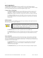
Operation Manual
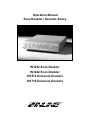
Scan Doubler / Decoder Series
IN1222 Scan Doubler
IN1422 Scan Doubler
IN1510 Universal Decoder
IN1710 Universal Decoder
®
1
INTRODUCTION
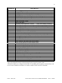
This manual covers the installation, operation, and specifications for the IN1222 / IN1422 Scan Doublers
and the IN1510 / IN1710 Universal Decoders. These four units are virtually identical in operation and
functionality. The main difference between the various models is the output signal scan rate (doubled /
undoubled), the size of the case (1/2 rack or full rack), and the type of connectors used for audio and
video connections. In the IN1510 and IN1710 decoders, the Composite Video or S-Video input signals
are decoded and output as an RGB interlaced video signal at the same frequency as the original signal.
The IN1222 and IN1422 scan doublers first decode the input signal (using the same circuitry as the
IN1510 / IN1710) and then double the number of scan lines. The IN1222 / IN1422 output a noninterlaced RGB video signal at twice the horizontal scan rate of the original input signal. Functions
which apply to the IN1222 / IN1422 but not the IN1510 / IN1710 will be designated in this manual as
IN1222 / IN1422 only. The chart below indicates the major differences between the four models.
MODEL
IN1222
IN1422
IN1510
IN1710
Size
Height Width
1U
1U
1U
1U
1/2 Rack
Full Rack
1/2 Rack
Full Rack
Output
Decode / Double
X
X
X
X
X
X
Freeze
Frame
Video
Blankin
Input / Output
Connectors
X
X
Compact Connectors / Adapters
Full Professional Connectors
Compact Connectors / Adapters
Full Professional Connectors
X
X
DESCRIPTION
The INLINE Scan Doubler / Decoder Series offers advanced decoding and scan doubling capabilities
with the following features:
♦ Universal digital decoding for NTSC, PAL, or SECAM video signals
♦ Digital scan doubling (IN1222/IN1422 only) improves video signals by doubling the number of
scan lines, resulting in a non-interlaced video image output at twice the input signal’s horizontal scan
frequency. The primary benefit of scan doubling is the elimination of visible scan lines, resulting in
a solid, film-like image. Additional benefits include a marked reduction of line flicker and crosscolor interference.
♦ Two Doubling Modes :
Line Doubling - Best for motion video sources, minimizes motion artifacts.
Frame Mode - Best for still video sources, maximizes image detail.
♦ 4 x 1 Video/Audio Switching:
Three inputs for Composite Video / S-Video with stereo audio
One RGB input with stereo audio (passive, no decoding or doubling)
♦ RS-232 control of all parameters
♦ Front panel controls to adjust signal parameters - Hue, Color, Sharpness/Contrast, and Volume.
♦ Gamma Correction - 7 different gamma curves allow compensation for display device
characteristics
♦ Input Memories - users may store a unique set of signal parameter adjustments for each input (Hue /
Color / Contrast / Gamma / Composite Video / S-Video / Volume / Doubled / Undoubled, etc.).
Settings are automatically recalled each time an input is selected
♦ Selectable output sync configuration: RsGsBs, RGBS, or RGBH&V
♦ Horizontal position control (available through RS-232 control in non-doubled mode only)
♦ Disable scan doubling allows the units to function as decoders only (IN1222/IN1422 only).
♦ Digital freeze frame provides rock-solid still video images (IN1222/IN1422 only).
©1994 - INLINE, INC.
IN1222 / IN1422 / IN1510 / IN1710 OPERATIONS MANUAL - REV. 2 12/04/99
2
INPUT COMPATIBILITY
The IN1222/1422 and IN1510/1710 will operate with NTSC, PAL, or SECAM input signals in
composite video or S-video format. For a complete listing of compatible input video standards see page
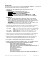
20. All video and audio input jacks are shown in the diagrams on pages 3, 6 & 7.
Composite Video / S-Video Signals
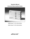
The IN1222 and IN1510 feature three 4-pin mini-DIN connectors for direct connection of SVideo signals. Composite video signals may be connected to Inputs 1, 2 and 3 by using an
IN9091 adapter (included), which features a female RCA connector for composite video input.
The IN1422 and IN1710 feature three female BNC connectors for composite video input and
three mini-DIN connectors for S-video input, allowing up to six video sources to be connected
simultaneously.
RGB Video Signals
Input #4 on all units is a passive RGB input which will accept virtually any video signal in any format
(the unit will pass up to five signal components).
RGB signals sent into Input 4 are not decoded, doubled, or altered in any way and
simply pass through the unit. This passive input is typically used to hook up a
computer to the doubler/decoder, allowing users to switch between the computer
video input and various composite video or S-video inputs.
The IN1222/IN1510 provide a female 15-pin HD connector for the RGB input.
The IN1422/IN1710 provide a female 15-pin HD connector and 5 BNC connectors for the RGB
input. These two connectors are wired in parallel and only one of them should be used at any
time.
Stereo Audio Signals
All units include a stereo audio input jack for each of the four inputs. The units feature audio-followvideo switching meaning that any time an input is selected, one video signal and its companion audio
stereo pair are simultaneously routed through the doubler/decoder. The audio inputs are unbalanced and
are intended for line level audio signals.
The IN1222/IN1510 feature four 3.5 mm ring-tip-sleeve type female jacks for audio input.
IN9090 adapters (3.5 mm male to 2-RCA female) are included with the unit to facilitate
connection of audio input signals.
The IN1422/IN1710 feature a pair of RCA female jacks for each input (no adapters required).
IIN1222 / IN1422 / IN1510 / IN1710 OPERATIONS MANUAL - REV. 2 12/04/99
©1994 - INLINE, INC.
3
OUTPUT COMPATIBILITY
All INLINE decoders and doublers offer a high quality 24-bit output video signal. The units may be set
to any of the following output signal formats as required: RGBS, RGBHV, and RsGsBs (for information
on changing output sync formats see page 14). The RGB Video and audio output connections are shown
in the diagrams on pages 3, 6 & 7.
The IN1510/IN1710 and the IN1222/IN1422 in interlaced (non-doubling) mode output a signal with the
same scan rate as the input signal. The decoded signal is compatible with many RGB monitors, video
projectors with RGB inputs and will also operate with many LCD projection panels.
The IN1222/IN1422 in non-interlaced (doubling) mode output a signal at twice the original scan rate.
RGB monitors, data projectors, and LCD panels capable of displaying a 31.5 KHz VGA signal (640 x
480 mode) can be used to display the decoded/doubled output signal.
RGB Video Output
The IN1222/IN1510 feature a 15-pin HD female output connector. One IN9045 output adapter
cable (15-pin HD male to 5-BNC male, 12’ long) is included with each unit.
The IN1422/IN1710 feature both a 15-pin HD female connector and 5 female BNC connectors.
The two RGB outputs are wired in parallel and may not be used simultaneously.
Stereo Audio Output
All units route the selected audio signals to the output connector as an unbalanced line level signal. The
output voltage gain varies according to the VOLUME setting for the selected input.
The IN1222/IN1510 feature a 3.5 mm ring-tip-sleeve type female jack for audio output. An
IN9090 adapter (3.5 mm male to 2-RCA female) is included with the unit to facilitate connection
to other audio devices.
The IN1422/IN1710 feature a pair of RCA female jacks for the stereo audio output.
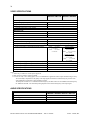
IN1222 / IN1510 REAR PANEL - INPUT / OUTPUT CONNECTORS
IN1422 / IN1710 REAR PANEL - INPUT / OUTPUT CONNECTORS
©1994 - INLINE, INC.
IN1222 / IN1422 / IN1510 / IN1710 OPERATIONS MANUAL - REV. 2 12/04/99
4
INSTALLATION
This section offers step-by-step instructions for installing an IN1222/1510 or IN1422/1710. Detailed application
drawings showing all equipment connections are included on pages 6 & 7.
1. Connect the video, audio, and RGB input signals to the appropriate input connectors:
IN1222/IN1510
S-Video signals may be connected directly to Inputs 1, 2 & 3.
Composite video signals may be connected by using IN9091 adapters.
Audio signals may be connected using the IN9090 adapters.
An RGB signal may be connected to Input 4 using an IN8000 Series cable, an IN9045
cable or any other adapter which conforms to the pin outs (see page 15 for pin-out details).
IN1422/IN1710
These units feature one mini-Din connector and one BNC connector for each video input
(Inputs 1 - 3) allowing up to three S-video sources and three Composite video sources to be
connected simultaneously. Please note that there is only one pair of RCA connectors per input
so if two signals are connected to an input, only one may have an audio signal.
An RGB signal may be connected to the 15-pin HD connector or the 5-BNC connectors. These
are wired in parallel and only one of them should receive an input signal.
2. Connect the output signal cable between the scan doubler / decoder output and the display device’s
RGB input using one of the cables listed below. Pin out information is located on page 15.
15 Pin Output
IN9045 15-Pin HD Male to 5-BNC Male, 12’ long (included with 1222/IN1510)
IN8000 Series 15-Pin HD Male to 15-Pin HD Female, various lengths 6’ - 100’
5 BNC Output
IN7000/IN7400 Series 4 or 5-BNC Cables, various lengths from 6’ - 100’
(IN1422/IN1710) IN7600/IN7700 Series 4 or 5-BNC Heavy Duty High Resolution Cables
3. Connect a control system, computer or other source for serial commands to the RS-232 REMOTE
connector if desired. For more information on remote control of the units, see pages 16 - 19.
4. Connect a power cable between the POWER input and an A/C power source. The unit utilizes a
switch mode power supply which automatically adjusts from 96 - 260 volts and 50 - 90 Hz.
5. Set the output sync format as needed to match installation requirements (see page 14).
6. Using the front panel controls or RS-232 commands (see pages 16 - 19), adjust and store the video
parameters for each input source. For best results, the following order is suggested:
Select S-Video or Composite Video (page 10)
Select Doubled or Straight Video (IN1222/IN1422 only) (page 13)
Select Doubling Mode: Line Doubling or Frame Mode (IN1222/IN1422 only) (page 13)
Select Gamma Curve (page 10)
Adjust Sharpness/Contrast (page 9)
Adjust Hue (page 9)
Adjust Color saturation (page 9)
Adjust Volume level (page 9)
Store Settings for that input - hold INPUT SELECT button until LED flashes (page 8)
IIN1222 / IN1422 / IN1510 / IN1710 OPERATIONS MANUAL - REV. 2 12/04/99
©1994 - INLINE, INC.
5
RACK MOUNTING
The IN1222 / IN1510 and IN1422 / IN1710 may be mounted in a standard 19" equipment rack using the
appropriate mounting hardware and procedure listed below:
IN1222 / IN1510 - Use the IN9083 Rack Ears - 1 U high (optional, not included with units). The
IN9083 Rack Mounting kit includes two rack ears and four mounting screws which are slightly longer
than the original case screws.
IN1422 / IN1710 - Use the IN9123 Rack Ears (included with each unit). The IN9123 Rack Mounting
Kit includes two rack ears and six mounting screws which are slightly longer than the original case
screws.
Installation Procedure
The IN1222 / IN1510 and IN1422 / IN1710 are exactly 1 U high without the feet.
If other equipment will be located in the space immediately below the scan doubler /
decoder, the installer may have to remove the feet from the bottom of the case before
mounting the unit in the equipment rack.
1. Remove power from the scan doubler / decoder.
2. Remove the case screws and retain for future use.
3. Place the rack ears along each side of the case, aligning the rack ear holes with the holes in
the side of the case.
4. Use the provided mounting screws to attach the rack ears to the scan doubler / decoder case.
5. Mount the unit in a 19" EIA standard equipment rack using standard rack mounting screws.
The shorter original case screws must be used to hold together the case if the rack
ears are ever removed. If the longer screws are used in the case without the rack
ears, they will extend too far into the unit, causing serious damage to the internal
circuitry. This type of damage is not covered under warranty.
©1994 - INLINE, INC.
IN1222 / IN1422 / IN1510 / IN1710 OPERATIONS MANUAL - REV. 2 12/04/99
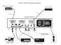
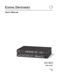
IN1222 / IN1510 Application Diagram
RGB Projector / Monitor
Control System
IN9045
IN1222 / IN1510
REPLACE WITH .5A 250V FUSE ONLY
RGBH&V
OUT
RGBH&V INPUT 4
1
1
2
S-VHS/VIDEO IN
2
RS-232 REMOTE
3
4
AUDIO
3
AUDIO
IN
O U T
90-260V .5A MAXIMUM POWER 30W
IN9090
IN9091
To Audio System
Line Level Input
Video Camera
Composite Video
Laser Disc Player
S-Video Output
S-VHS VCR
S-Video Output
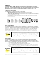
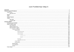
IN1422 / IN1710 Application Diagram
Multimedia PC
w/ VGA & Stereo Audio
RGB Projector / Monitor
Control System
To Audio System
Line Level Input
IN7600 or IN7700 Series
4-BNC or 5-BNC Cable
IN2060
VIDEO
OUTPUT
®
2060
DISTRIBUTION AMPLIFIER
IN8000 Series
VGA Cable
INPUT 1
RIGHT
LEFT
VIDEO
S-VIDEO
INPUT 2
LEFT
VIDEO
RIGHT
S-VIDEO
INPUT 4
INPUT 3
LEFT
VIDEO
RIGHT
S-VIDEO
RGB (PASSIVE)
R
G
OUTPUT
LEFT
RIGHT
B
H/S
RGB
V
R
G
RS-232
LEFT
RIGHT
B
H/S
IN1422 / IN1710
Video Camera
Composite Video
Laser Disc Player
S-Video Output
S-VHS VCR
S-Video Output
V
REPLACE WITH 5A 250V FUSE ONLY
90-260V 5A MAXIMUM POWER 30W
8
OPERATION
The IN1222 / IN1510 / IN1422 / IN1710 may be controlled by the front panel buttons or through the
RS-232 port. All switching functions and most video / audio adjustment functions can be accessed using
the front panel. A few adjustments are available only through RS-232 control (see pages 16 - 19).
Using the Front Panel Controls
The control panel is divided into three types of control buttons:
Input Select Buttons are the four large buttons on the left end of the panel.
Audio / Video Adjustment Buttons are located in the center and include a pair of small buttons
to adjust each parameter up or down.
Function Buttons are three small buttons located on the right end of the panel which toggle
between various modes.
INPUT SELECT Buttons
The buttons labelled VIDEO 1, VIDEO 2, VIDEO 3, and RGB may be used to select the desired input
video source. The stereo audio associated with that input will automatically be selected at the same time.
Whenever the unit is first turned on, INPUT 1 is automatically selected. The RGB input is passively
routed through to the output at power down. To select an input, press and release one of the INPUT
SELECT buttons. A green LED will light in one of the four buttons to indicate the current selection.
The INPUT indicator LEDs work in conjuction with the VOLUME, HUE, COLOR,
and CONTRAST up and down adjustment buttons. When an input source is being
adjusted the corresponding INPUT SELECT LED will flash. If the LED stops
flashing while adjustments are being made, the controls have reached the upper
or lower limit of their adjustment range.
Storing Settings
The INPUT SELECT buttons are also used to store the unique audio and video settings for input
channels 1 - 3 and the VOLUME setting on Input 4. By following the procedure which follows, each
input source can be fine tuned and all settings stored for automatic recall whenever that input is selected:
1. Select the desired input using an INPUT SELECT button.
2. Make all desired audio and video adjustments for that input source.
3. Save all settings by pressing and holding the same INPUT SELECT button for five seconds.
The INPUT SELECT LED will flash to indicate that all settings have been stored for that input.
4. Repeat steps 1 - 3 for each input source.
The Store Settings procedure stores all important parameters for each input
including Volume, Hue, Color, Contrast, Gamma, Video/S-Video, Doubling Mode,
and SECAM enable/disable. If changes are made to an input and the settings are
not stored, those changes will be lost if the unit is switched to a different input.
The unit always recalls the last stored settings whenver an input is selected.
IIN1222 / IN1422 / IN1510 / IN1710 OPERATIONS MANUAL - REV. 2 12/04/99
©1994 - INLINE, INC.
9
VOLUME Control
Volume levels may be adjusted and stored for each of the four inputs in order to compensate for different
audio input levels from the various sources. The volume circuitry is active, allowing the output signal
voltage to be set either higher or lower than the original input signal. Press the upper button to increase
the volume level or the lower button to decrease the volume level. If either button is pressed and quickly
released, the volume level will change up or down by one step out of a total adjustment range of 40 steps.
If either button is pressed and held the volume will quickly increase or decrease.
If no volume level has been stored for an input, the factory default level (15 steps below maximum) is
automatically recalled each time the input is selected or at power on.
Bass and treble can also be adjusted and stored for inputs 1 - 4 using RS-232 commands (pages 18 & 19).
HUE Control
This control functions for Inputs 1 - 3 when receiving NTSC input signals (it has no effect on PAL or
SECAM input signals). The HUE control has no effect on the passive RGB input. The top button skews
the hue phase toward the Red end of the color spectrum and the bottom button adjusts the phase towards
the Green end of the spectrum. Pressing either button once quickly adjusts the hue setting by one step
out of a total adjusment range of 63 steps. Press and hold either adjustment button for a continuous rapid
hue adjustment. The factory default setting is in the middle of the range.
COLOR Control
The unit employs an automatic color level circuit, and the color saturation level can be adjusted over a
limited range (±5%). The COLOR control will not reduce the color to zero. The COLOR control has
no effect on the passive RGB input. The top button increases the color saturation and the bottom button
decreases the color saturation. Pressing either button once quickly adjusts the color setting by one step
out of a total adjusment range of 8 steps. Press and hold either adjustment button for a continuous rapid
color adjustment. The factory default setting is three steps above the minimum setting.
CONTRAST Control
Along with the GAMMA control, the CONTRAST control is very critical for proper adjustment of
the unit. The control labeled CONTRAST actually controls both contrast and sharpness. The unit has
been programmed with 32 contrast / sharpness settings. Every time an upper or lower button is pushed
the unit will change one "click" to the next setting. Press and hold either adjustment button for a
continuous rapid adjustment.
The factory default setting is at the bottom of the range (contrast and sharpness
set for flat gain). The higher contrast settings are located at the top of the
adjustment range. It is recommended that users set the CONTRAST control to
the extreme top position and move down one step at a time until a pleasing
picture is attained. For most applications, the best image will occur with one
of the 6 - 8 highest sharpness / contrast settings.
©1994 - INLINE, INC.
IN1222 / IN1422 / IN1510 / IN1710 OPERATIONS MANUAL - REV. 2 12/04/99
10
GAMMA Button
Gamma correction is an effective tool used to compensate for the non-linear response of most display
devices. The gamma setting may also be changed as required to accomodate the wide variation of video
gain and contrast characterstics found in various video program sources. INLINE scan doublers and
decoders offer eight different gamma curve adjustments (seven active gamma curves plus no gamma).
Along with the CONTRAST control, the GAMMA control setting is critical to proper adjustment and
should generally be set first with all other controls set to the factory default position.
The default setting is Gamma Curve 0 (no gamma correction). Each time the GAMMA button is pressed,
the unit moves one click up to the next gamma curve. The complete cycle includes eight gamma settings,
beginning with Gamma Curve 0 and ending when Gamma Curve 7 is reached, at which point it jumps
back to Gamma Curve 0.
The GAMMA select LED is off when Gamma Curve 0 is selected (no gamma correction).
The GAMMA select LED is on when an active gamma curve is selected (Curves 1 - 7).
S-VIDEO / VIDEO / SECAM Button
Inputs 1, 2 and 3 can accept either S-Video or Composite Video input, but the unit must first be set to
accept and decode one one these formats. The primary function of this button is to toggle between SVideo or Composite Video input.
S-Video input is selected when the LED is on (factory default setting).
Composite video input is selected when the LED is off.
It is very important to store the appropriate S-Video / Video setting for each
input source during the installation process (see Store Settings procedure listed
on page 8). This will insure proper decoding when switching between inputs.
Selecting SECAM Video
The unit will automatically detect and decode NTSC and PAL input signals. SECAM decoding is
normally disabled (factory default setting) and must be manually selected using the S-VIDEO / VIDEO /
SECAM button. To decode SECAM input signals, hold down the button until the INPUT SELECT LED
flashes three times and a normal video image is displayed. Store this selection (Store Settings, page 8).
IIN1222 / IN1422 / IN1510 / IN1710 OPERATIONS MANUAL - REV. 2 12/04/99
©1994 - INLINE, INC.
11
FREEZE FRAME Button (IN1222 / IN1422 only)
The FREEZE FRAME button may be used to store and view a single video frame. The digital freeze
frame offers a perfectly still image of a single video frame for extended study or presentation purposes.
This provides a much better image than the freeze frame feature found on most VCRs. Each time the
FREEZE FRAME button is pressed it toggles the unit between Freeze Frame or normal motion video.
Freeze Frame is engaged when the LED is on.
Freeze Frame is disabled when the LED is off (normal motion image, factory default setting).
BLANKING Button (IN1510 / IN1710 only)
The BLANKING button offers a way to blank the decoder output. The sync signal is still sent, but a
black video image replaces the previous input selection. The BLANKING button toggles between
blanking on and blanking off each time the button is pressed.
Blanking is engaged when the LED is on.
Blanking is disengaged when the LED is off (normal picture, factory default setting).
©1994 - INLINE, INC.
IN1222 / IN1422 / IN1510 / IN1710 OPERATIONS MANUAL - REV. 2 12/04/99
12
SCAN DOUBLING PRIMER
Garden variety composite video or S-Video images are interlaced, meaning that the picture information
from each video frame is split into two fields. Field one contains all of the odd horizontal lines and Field
two contains all of the even horizontal lines. Each field is displayed for only 1/60 of a second, so the
human eye actually merges all the odd and even lines from the two fields into a single image which is
refreshed completely 30 times a second (timings are for NTSC). Unfortunately, this merging process is
not perfect and we can easily perceive the video scan lines, especially on large screen displays.
Scan doublers increase the number of scan lines resulting in a new type of video image, IDTV which
stands for Improved Definition Television. The images are no longer in their original NTSC, PAL, or
SECAM format since they have been decoded to an RGB format, the number of scan lines has been
doubled, and the horizontal scan rate has been doubled. Scan doublers output a non-interlaced image,
and employ progressive scanning, where the image is completely drawn in a single pass from the top to
the bottom of the screen before moving to the next frame. Scan doubled images are virtually free from
scan lines and have a solid, film-like appearance. Various methods are employed by scan doublers to
achieve a non-interlaced, scan doubled image and two of these techniques are discussed in the following
section.
Scan doublers double the horizontal scan rate, but the vertical refresh rate is not
changed. If the input video signal is 50 Hz the output signal will still be 50 Hz.
LINE DOUBLING TECHNIQUES
The IN1222 and IN1422 will allow users to select and store a different line doubling technique for each
input as required by the type of input source. The IN1222 / IN1422 offer three choices: Line Doubling,
Frame Mode, and Disable Doubling.
Line Doubling - is the default mode for INLINE scan doublers and is best for displaying motion video
sources with minimal motion artifacts. This method stores a single field and displays each line within the
field twice (the first and last lines of the frame are only displayed once). Looking from top to bottom on
the display would be:
Field One - Line 1, Line 3, Line 3, Line 5, Line 5, etc. for the first 1/60th of a second and
Field Two - Line 2, Line 2, Line 4, Line 4, Line 6, Line 6, etc. for the second 1/60 of a second.
Frame Mode - is the preferred mode for still video, offering the greatest image detail on input sources
such as document cameras and slide-to-video converters. While frame mode offers the best detail for
still sources, it should not be used with motion video sources, as extreme motion artifacts will occur.
In Frame Mode (also known as Field Overlay) the scan doubler stores both fields of one frame in
memory and then displays both fields on the screen at the same time. The display would appear from top
to bottom as follows:
Line 1, Line 2, Line 3, Line 4, Line 5, Line 6, etc. for 1/60th of a second.
The same image is actually displayed twice, for a total time of 1/30th of a second.
Disable Doubling - Low quality video images with excessive noise or poor detail may not benefit from
scan doubling, therefore the IN1222 and IN1422 provide a way to disable the scan doubling on selected
inputs. The output video is still decoded from composite video or S-Video to RGBHV (or other selected
output format), but the signal remains at its original horizontal scan rate and is still interlaced.
IIN1222 / IN1422 / IN1510 / IN1710 OPERATIONS MANUAL - REV. 2 12/04/99
©1994 - INLINE, INC.
13
Selecting Doubling Modes (IN1222 / IN1422 Only)
The following procedure will allow users to select and store the desired doubling mode (or disable
doubling) for Inputs 1, 2, and 3.
1. Turn the unit power on.
2. Select the desired input channel and make the necessary installation adjustments.
3. Hold down the appropriate front panel button (see chart below) continuously for 3 seconds until the
button LED flashes twice. This indicates that the doubling method has been changed for that input.
Release the button.
4. Store the doubling mode selection and all other adjustments by pressing and holding the INPUT
SELECT button for the source currently being adjusted (hold for 5 seconds until LED flashes).
5. Repeat Steps 1 - 4 for other input(s) as desired.
Doubling Mode
Line Doubling (factory default)
Frame Mode
Enable Doubling (factory default)
Disable Doubling
Hold Down Button
Press GAMMA button for three seconds
Press GAMMA button for three seconds
Press FREEZE button for three seconds
Press FREEZE button for three seconds
Each of the button presses listed above causes the unit to toggle between Line Doubling / Frame Mode or
Enable / Disable Doubling. If the user is unsure of current settings, it is best to begin the installation by
resetting the unit to factory defaults (Line Doubling Mode, Doubling Enabled). The unit may be reset to
factory default settings by pressing and holding the VIDEO 1 channel select button while toggling the
power switch to "ON". Please note that this will reset all video and audio adjustments, so it is generally
best to do this at the beginning of the set-up procedure before adjustments have been stored.
©1994 - INLINE, INC.
IN1222 / IN1422 / IN1510 / IN1710 OPERATIONS MANUAL - REV. 2 12/04/99
14
POWER ON ADJUSTMENTS
The IN1222 / IN1510 / IN1422 / IN1710 utilize "Power On" settings to control two setup parameters. In
order to access a Power On adjustment, the user must hold down the indicated button continuously while
toggling the unit’s power switch to "ON" (if power is already on, the user can hold down the indicated
button and switch the power off and then back on).
Reset to Factory Defaults
The IN1222 / IN1510 and IN1422 / IN1710 offer a powerful set of controls for adjusting video and
audio parameters. If the set-up technician or users have changed several of the parameters and want to
get back to average settings, the simplest way is to reset the unit to the factory default settings.
Reset to Factory Defaults: Hold down the VIDEO 1 Channel Select button while turning power on. This
resets the video / audio adjustments for all input channels to factory default settings:
Video / Audio:
Channel Selection:
Video / S-Video:
Gamma:
SECAM:
Scan Doubling:
Doubling Mode:
Baud Rate:
Command Codes:
All adjustment parameters set to factory defaults (average settings)
Input 1 Selected (Input 1 is selected each time the power is turned on)
S-Video selected for all input channels
Gamma Curve 0 (no Gamma Correction)
SECAM disabled (unit automatically decodes NTSC or PAL)
Enabled (IN1222 / IN1422 only)
Line Doubling (IN1222 / IN1422 only)
1200
[]
Output Sync Format is not effected by the Power On "Reset to Factory Defaults."
Output Sync Format can only be changed by using the Power ON settings described
in the paragraph below or by using RS-232 commands (see page 19).
Select Output Sync Format
The IN1222 / IN1510 / IN1422 / IN1710 feature flexible output sync format capability. This allows
users to select an output video format which meets the needs of both the video switching / distribution
system and the display device. Users who wish to emulate a standard 640 x 480 VGA signal should
select the factory default output format, which is RGBHV with negative sync polarities.
Holding down the appropriate button at Power On will change the output signal to the desired format:
Output Sync Format
RGBHV(++)
RGBHV(--)
RGBS
RsGsBs
Hold Down Button at Power On
VOLUME UP
HUE UP
COLOR UP
CONTRAST UP
IIN1222 / IN1422 / IN1510 / IN1710 OPERATIONS MANUAL - REV. 2 12/04/99
©1994 - INLINE, INC.
15
UNIVERSAL POWER SUPPLY
The IN1222 / IN1510 / IN1422 / IN1710 employ a universal (switch mode) power supply which
automatically adjusts to accept input voltages worldwide. Input voltage can range between 96V and
260V AC and frequency may range from 50 Hz to 90Hz. The power entry module uses an IEC standard
male connector for power connection. U.S. domestic units are shipped with a standard IEC female to
Edison male power cable.
Changing Fuses
The power entry module includes a quick-change fuse holder located to the left of the power switch.
This holder contains the main fuse and a spare fuse. If the fuse blows:
1. Remove the power cord from the unit.
2. Use a flat blade screwdriver to remove the fuse holder.
3. Replace the blown fuse with the spare fuse.
4. Replace the spare fuse with a new .5A 250V slow blow fuse.
5. Seat the fuse holder back into the power entry module and reattach the power cord.
THE IN1222 / IN1510 / IN1422 / IN1710 CONTAIN NO INTERNAL FUSES,
JUMPERS, DIP SWITCHES OR OTHER USER SERVICABLE PARTS. IF
THE CASE IS OPENED THERE IS ELECTRIC SHOCK HAZARD AND
DAMAGE MAY OCCUR TO THE COMPONENTS. REFER ALL SERVICE TO
INLINE.
RGB PIN OUT INFORMATION
The following information applies to the 15-pin HD connectors on the IN1222 / IN1510 / IN1422 /
IN1710. The IN1422 / IN1710 also include a set of 5 - BNC Female connectors for RGB input and
output.
Input 4 - RGB Passive Input
RGB Output
Input 4 and the RGB output both employ a 15-pin HD female connector with the following pin-outs:
Pin 1
Pin 2
Pin 3
Pin 4
Pin 5
Pin 6
Pin 7
Pin 8
Red Signal
Green Signal
Blue Signal
No connection
Ground
Red ground
Green ground
Blue ground
Pin 9
Pin 10
Pin 11
Pin 12
Pin 13
Pin 14
Pin 15
No connection
Ground
No connection
No connection
Horizontal Sync or Composite Sync Signal
Vertical Sync Signal
No connection
The output sync format for decoded / doubled images (Inputs 1 - 3) has no effect on the output format of
RGB signals sent into Input 4. For instance, if the scan doubler is set to output RGBS, an RGBHV signal
applied to Input 4 will still appear at the output as RGBHV, but the decoded / doubled signals will appear
at the output as RGBS.
©1994 - INLINE, INC.
IN1222 / IN1422 / IN1510 / IN1710 OPERATIONS MANUAL - REV. 2 12/04/99
16
USING RS-232 CONTROL
The IN1222/IN1510 and IN1422/IN1710 include an 9-pin REMOTE CONTROL port which will accept
serial commands from a control system, computer serial port, or any other device capable of sending out
serial ASCII commands at compatible baud rates. All switching, adjustment, and set-up parameters can
be controlled using RS-232 commands. A few functions cannot be accomplished from the front control
panel and are available only through RS-232 control:
Audio Mute
Audio Bass and Treble Control
Comprehensive Control of Individual Contrast Filter Settings and Coring Settings
Horizontal Picture Centering (non-doubling mode only)
Saving the settings from one input to other selected inputs
Changing the RS-232 Baud Rate
Changing the command codes (delimiters)
Getting Firmware Information on the Microcontroller
Details on the commands above, and a complete listing of RS-232 codes is included on pages 18 & 19.
COMMUNICATION PROTOCOL
8 data bits
1 stop bit
No parity check
1200 baud (factory default setting)
BAUD RATE SELECTION
The IN1222 / IN1510 / IN1422 / IN1710 have a factory default baud rate of 1200 and can communicate
at baud rates from 1200 up to 19200. Baud rates can only be changed and saved via RS-232 commands
(see page 18).
The units revert back to a baud rate of 1200 each time the power is turned off. If the unit will be turned
on and off frequently and the control system is going to use one of the higher baud rates, then the
"SAVE0" command (save global settings) should be used to save the appropriate baud rate and command
code settings. Once the settings have been saved this way, the unit will recall the new baud rate and
command codes at power up.
IIN1222 / IN1422 / IN1510 / IN1710 OPERATIONS MANUAL - REV. 2 12/04/99
©1994 - INLINE, INC.
17
COMMAND CODE STRUCTURE
All commands sent to the unit must contain a leading code, the command code, and an ending code.
Each command must be completely executed before the unit will accept a new command. When a
command is completed, the unit provides a response code; "OK" indicates the command was received
and executed,
"ERR" indicates there is a problem with the code and the command was not executed.
INLINE doublers and decoders can be set to recognize one of four sets of leading codes and ending
codes.
These are: [ ] { } ( ) < > . The factory default for leading / ending codes is [ ]. The unit can
only be set to a different command code by using an RS-232 command (see page 18).
A complete command consists of:
[
CH4
]
The leading code
The command code. In this case CH4 would select the RGB input.
The ending code
Sample command codes:
[CH1]
Selects input 1
[GAM3]
Selects Gamma Correction curve 3 for the current input channel
Controlling Multiple INLINE Products
INLINE products such as the Pathfinder, V-Net, the IN1222 / IN1240 / IN1422 doublers and the
IN1510 / IN1540 / IN1710 decoders use a similar communications protocol and command code
structure. By setting each unit to a different command code pair, up to four different INLINE products
can be controlled by a single RS-232 serial control port. Once a unit is set to look for a certain pair of
leading and ending delimiters (command codes), it will ignore all other commands sent by the port.
When daisy chaining multiple units together the 9-pin RS-232 control cable between the units must be
wired in parallel. The receive pin on all units must be connected together. Do not connect the transmit
pin between units.
CONTROL PORT PIN-OUTS
The RS-232 control port is located on the rear panel just to the left of the power
switch. The control port uses a 9-Pin D male connector and the pin outs are:
©1994 - INLINE, INC.
Pin#
Signal
2
3
5
Receive
Transmit
Ground
IN1222 / IN1422 / IN1510 / IN1710 OPERATIONS MANUAL - REV. 2 12/04/99
18
RS-232 ASCII CODES
The table below lists the ASCII control codes for the IN1222 / IN1510 / IN1422 / IN1710. These are
virtually identical to the codes used with the IN1240 / IN1540, and new codes for the current version are
indicated by an asterisk (*). The most current version of firmware as of this writing is V1.4a.
COMMAND
ACI3
ACI4
ACI5
ACI6
ACI7
BAS+
BASBAS,
BASxxx
CMDCD0
CMDCD1
CMDCD2
CMDCD3
CH1
CH2
CH3
CH4
CON+
CONCON,
CONxxx
FRZ0
FRZ1
GAM0
GAM1
GAM2
GAM3
GAM4
GAM5
GAM6
GAM7
HSCAN0
HSCAN1
DESCRIPTION
Set ACI to 1200 baud rate default
Set ACI to 2400 baud rate
Set ACI to 4800 baud rate
Set ACI to 9600 baud rate
Set ACI to 19200 baud rate
Increase Bass level by 3dB
Decrease Bass level by 3dB
Set Bass level to 0dB default
Set Bass level to value xxx: range for xxx is 240 - 255
Select command code "[" & "]" default
Select command code "{" & "}"
Select command code "(" & ")"
Select command code "<" & ">"
Select Input 1 power on default setting
Select Input 2
Select Input 3
Select Input 4 - RGB Passive Input
Increase CONTRAST level 1 step
Decrease CONTRAST level 1 step
Set CONTRAST level to normal setting default
Set CONTRAST level to xxx value, xxx: 000-255
Disable Freeze Frame (Disable Blanking on IN1510/IN1710) default
Freeze Current Frame (Enable Blanking on IN1510/IN1710)
Disable GAMMA Correction function default
Select GAMMA Correction curve 1
Select GAMMA Correction curve 2
Select GAMMA Correction curve 3
Select GAMMA Correction curve 4
Select GAMMA Correction curve 5
Select GAMMA Correction curve 6
Select GAMMA Correction curve 7
(IN1222/IN1422 only) Disable doubling for current input (15.75 kHz output signal)
(IN1222/IN1422 only) Enable doubling for current input (31.5 kHz output) default
IIN1222 / IN1422 / IN1510 / IN1710 OPERATIONS MANUAL - REV. 2 12/04/99
©1994 - INLINE, INC.
19
COMMAND
HUE+
HUEHUE,
HUExxx
INTP0
INTP1
INF0
*
MUTE0
MUTE1
POSTL
POSTR
POSTHxx
SAT+
SATSAT,
SATxxx
SAVE
SAVEs
SAVE0
SEC0
SEC1
SVIDEO0
SVIDEO1
SYNC0
**
SYNC1
**
SYNC2
**
SYNC4
**
TRE+
TRETRE,
TRExxx
VOL+
VOLVOLxxx
VOL,
DESCRIPTION
Increase HUE phase 1 step
Decrease HUE phase 1 step
Set HUE phase to normal setting default
Set HUE phase to xxx value, range for xxx: 000-255
(IN1222/IN1422 only) Set Doubling Mode to Line Doubling default
(IN1222/IN1422 only) Set Doubling Mode to Frame Mode
Get the model number & firmware version
Disable Audio Mute default
Enable Audio Mute
Horizontal position adjustment - shift left
(Only when doubling is disabled)
Horizontal position adjustment - shift right
(Only when doubling is disabled)
Horizontal position adjustment - set to xx, range of xx: 00-FF (Doubling disabled)
Increase COLOR level 1 step
Decrease COLOR level 1 step
Set COLOR level to normal setting default
Set COLOR level to xxx value, xxx: 000-255
Save current channel’s settings (Vol./Hue/Color/Cont./Gamma/S-Video/Doubling Mode/Secam)
Save the current channel’s settings to a selected channel s (s = 1, 2, or 3)
Save the global settings (baud rate, command code)
Disable SECAM decoder default
Enable SECAM decoder
Select composite video input for the current channel
Select S-Video input for the current channel default
Select H & V Output Sync, positive polarity
Select H & V Output Sync, negative polarity default
Select Composite Output Sync
Select Sync on RGB
Increase Treble level by 3dB
Decrease Treble level by 3dB
Set Treble level to 0dB default
Set Treble level to xxx value, range for xxx: 240 - 255
Increase volume 8dB
Decrease volume 8dB
Set volume level to xxx value, range for xxx: 192 to 255
Set volume level to normal, default
*This code prompts the unit for feed back and will result in special response codes.
**When the output sync is changed via these RS-232 commands, the new setting is automatically saved
as soon as the command is sent (there is no need to send the SAVE or SAVE0 command).
©1994 - INLINE, INC.
IN1222 / IN1422 / IN1510 / IN1710 OPERATIONS MANUAL - REV. 2 12/04/99
20
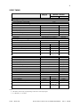
VIDEO SPECIFICATIONS
IN1510 / IN1710
IN1222 / IN1422
Video Input Characteristics
Input voltage (peak-to-peak)
Input impedance (terminated, f=6MHz)
Input capacitance (f=6MHz)
Crosstalk between the 3 input channels
0.6 - 1.4V
75Ω
35 - 45pF
−60 - −55dB
Digital Decoder
NTSC standards1
PAL standards1
SECAM standards1
NTSC -M
PAL -D, B, G, H, I
SECAM -L, B, D, G, H, K1
Video Control Characteristics
−180.0° - +178.6°
±5%
32 Pre-programmed settings
Hue phase (Available for NTSC only)
Color level (chroma gain)
Sharpness / Contrast level2
RGB Output Characteristics (for inputs 1-3, 75Ω doubly terminated)
Input to output delay (referenced to the input signal) 3
138/780 line
60Hz :
or 11.245µS
138/944 line
50Hz :
or 9.356µS
RGB output voltage (peak-to-peak value, without sync)
RGB output voltage (peak-to-peak value, with sync)
Sync output voltage HIGH
Sync output voltage LOW
Output impedance
Single Scan Mode
60Hz :
0.5+137/780 line
or 42.941µS
50Hz :
0.5+137/944 line
or 41.288µS
Double Scan Mode
60Hz :
1+137/780 line
or 74.720µS
50Hz :
1+137/944 line
or 73.288µS
0.7 - 0.8V
0.9 - 1.1V
2.4V min.
0.5V max.
75Ω
Notes:
1. Video only, no teletext or closed-caption supported.
2. Refer to the Programmer’s Guide for details.
3. For reference only. These timing figures are not recommended for applications which require absolute timing accuracy.
The actual delay is dependent on the quality of the input signal and will also be influenced by the position of the
video adjustment controls (Hue, Color and Sharp controls).
The delay time is based on a 15.734kHz horizontal frequency for 60Hz NTSC and 15.625kHz horizontal frequency
for 50Hz PAL/SECAM. The actual delay timing depends on the horizontal frequency of the input signal.
AUDIO SPECIFICATIONS
IN1222 / IN1422 / IN1510 / IN1710
Audio Inputs
Audio Outputs
Frequency Response
Signal to Noise Ratio
Stereo Unbalanced Line Level
Stereo Unbalanced Line Level
20 Hz to 20 KHz ±3dB
80dB
IIN1222 / IN1422 / IN1510 / IN1710 OPERATIONS MANUAL - REV. 2 12/04/99
©1994 - INLINE, INC.
21
VIDEO TIMING
IN1510
IN1710
IN1222 / IN1422
Single scan
Double scan
Input Signal Timing
Horizontal frequency of input signal
Vertical frequency of input signal
fH Hz
fV Hz
RGB Output Horizontal Timing (NTSC mode)
Pixel clock
Horizontal frequency (line rate)
Total pixels per line
Active pixels per line
Horizontal blanking interval
Horizontal synchronization pulse
Front porch
Back porch
780fH Hz
fH Hz
780 pixels
640 pixels
140 pixels
64 pixels
Adjustable (RS-232 Commands)
Adjustable (RS-232 Commands)
1560fH Hz
2fH Hz
780 pixels
640 pixels
140 pixels
64 pixels
56 pixels
20 pixels
fV Hz
½fV Hz
fV Hz
fV Hz
RGB Output Vertical Timing (NTSC mode)
Vertical frequency (field rate)
Frame rate
Total lines per field
Visible lines per field
Vertical blanking interval
Vertical synchronization pulse
Front porch
262.5 lines
241.5 lines
21 lines
6 lines4
3.5 lines4
Back porch
11.5 lines4
262.5 lines
241 lines
21.5 lines
6 lines
3.5 lines (of)
3 lines (ef)5
12.5 lines (of)
12 lines (ef)5
525 lines
481 lines
44 lines
12 lines
7 lines
25 lines
RGB Output Horizontal Timing (PAL/SECAM mode)
Dot clock
Horizontal frequency (line rate)
Total pixels per line
Active pixels per line
Horizontal blanking
Horizontal synchronization pulse
Front porch
Back porch
944fH Hz
fH Hz
944 pixels
768 pixels
176 pixels
64 pixels
Adjustable (RS-232 Commands)
Adjustable (RS-232 Commands)
1888fH Hz
2fH Hz
944 pixels
768 pixels
176 pixels
64 pixels
88 pixels
24 pixels
fV Hz
½fV Hz
fV Hz
fV Hz
RGB Output Vertical Timing (PAL/SECAM mode)
Vertical frequency (field rate)
Frame rate
Total lines per field
Visible lines per field
Vertical blanking
Vertical synchronization pulse
Front porch
Back porch
312.5 lines
287.5 lines
25 lines
6 lines4
3 lines4
16 lines4
312.5 lines
287 lines
25.5 lines
6 lines
2.5 lines (of)
3 lines (ef)5
16.5 lines (of)
17 lines (ef)5
625 lines
573 lines
52 lines
12 lines
5 lines
35 lines
Notes:
4. The number of lines may vary depending on the source of the input signal.
5. of: odd field, ef: even field.
©1994 - INLINE, INC.
IN1222 / IN1422 / IN1510 / IN1710 OPERATIONS MANUAL - REV. 2 12/04/99
22
GENERAL SPECIFICATIONS
IN1222 / IN1510
IN1422 / IN1710
(3) 4-Pin Mini DIN
Female
15-Pin HD Female
(3) 4-Pin Mini Din
(3) BNC Female
15-Pin HD Female
(5) Female BNC
15-Pin HD Female
(5) Female BNC
Video Connectors
Inputs 1, 2 & 3 - S-Video / Composite Video
Input 4 - Passive RGB
15-Pin HD Female
RGB Output
Audio Connectors
Inputs 1 - 4 - Stereo Audio
Output - Stereo Audio
Remote Control Connector
Power Supply
Input port
Input voltage / frequency
Power consumption
Fuse
(4) 3.5mm Mini Female
(4) Stereo Pairs RCA
Stereo (Ring/Tip/Sleeve)
Female
(1) 3.5mm Mini Female
(1) Stereo Pair RCA
Stereo (Ring/Tip/Sleeve)
Female
9-Pin D Male
IEC Standard Male Connector
96V - 260 VAC / 40 Hz - 90 Hz
10W
(1) .5A / 250V Slow Blow
Environmental Capabilities
Operating temperature
Storage & transport temperature
Operating relative humidity
Storage & transport relative humidity
Heat radiation
Operating vibration
Operating position
+5°C - +40°C
−20°C - +60°C
20 - 90%
5 - 95%
direct sunlight radiation not allowed
10-50Hz @ 2G
any position
Safety and EMI Data
Safety regulation
EMI regulation
Dimensions
Shipping Weight
UL applying
complies with FCC Class A
1.75" H x 8.5" W
1.75" H x 19" W
x 10.25" D
x 11.5" D
7.5 pounds
14 pounds
ACCESSORIES INCLUDED
IN1222 / IN1510
(1) - IN1222 Scan Doubler or IN1510 Decoder
(1) - IN9045 15-Pin HD Male to 5-BNC Male, 12’ long
(5) - IN9090 3.5mm Mini Male to 2-RCA Female
(3) - IN9091 4-Pin Mini DIN (S-Video) to RCA Female
(1) - IN9038 15-Pin HD Male to Male Gender Changer
(1) - Power Cord (U.S. Domestic units only)
(1) - Operations Manual
IN1422 / IN1710
(1) - IN1422 Scan Doubler or IN1710 Decoder
(1) - IN9123 Rack Mounting Kit
(1) - Power Cord (U.S. Domestic units only)
(1) - Operations Manual
IIN1222 / IN1422 / IN1510 / IN1710 OPERATIONS MANUAL - REV. 2 12/04/99
©1994 - INLINE, INC.
23
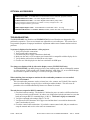
OPTIONAL ACCESSORIES
IN8000 Series Cables - 15 Pin HD Male to 15 Pin HD Female cables
IN8200 Series Cables - 15 Pin HD Male to 9 Pin D Female, for use with NEC projector switchers
IN7000/IN7400 Series Cables - 4 or 5 BNC High Resolution Cables
IN7600/IN7700 Series Cables - 4 or 5 BNC High Resolution Heavy Duty Cables
The Input and Output cables listed above are available in a variety of lengths from 6’ - 100’
with longer lengths available by special order.
IN9045 Output Adapter Cable - 15 Pin HD Male to 5 Male BNC Cable - 12’ Long
IN9083 Rack Mount Kit - For IN1222 / IN1510, includes (2) Rack Ears and (4) Attachment Screws
TROUBLESHOOTING
The IN1222/IN1422 Scan Doublers and IN1510/IN1710 Universal Decoders are designed to offer
problem free operation. There are no internal user adjustable or serviceable parts. This section lists a
few potential symptoms of improper installation / adjustment and the most common solutions to these
problems.
No picture is displayed on the monitor / video projector.
1. Verify all input cable connections.
2. Verify output cable connections.
3. Check the unit power supply connection at both ends.
4. Make sure the unit is set to an output sync format which is compatible with the display device.
5. Verify that the unit has been switched to an active input.
6. Check to see if the display device has been switched to its RGB input.
Two images are displayed side by side on the display screen. (IN1222/IN1422 only)
The IN1222/IN1422 is probably being used in its scan doubling mode with an incompatible monitor
or video projector. Either switch to the "Disable Doubling" mode (Page 13), or use an RGB display
device which is capable of showing a 31.5 KHz (VGA type) video signal.
When switching from one input to another the video and audio parameters are not recalled
properly for each channel.
The video and audio parameters such as volume, hue, color, contrast, and Video/S-Video must be
stored (see Store Settings on page 8) before switching to another channel. This will cause all
parameters to be recalled automatically whenever a channel is selected.
The unit does not respond to RS-232 commands.
1. Check the baud rate settings. The default is 1200 baud at power on (unless a different baud rate
has been previously set and stored). In order to use a higher baud rate the unit must be set to that
baud rate using an RS-232 command (Pages 16 & 18). 1200 baud is highly recommended.
2. Verify the command code settings (Pages 17 & 18).
3. Verify that all ASCII characters are in upper case and that there is no confusion between the
letter O and number 0 (zero).
4. Check the control cable construction. If you built a custom control cable, did you remember to
swap the transmit and receive so the units can communicate?
©1994 - INLINE, INC.
IN1222 / IN1422 / IN1510 / IN1710 OPERATIONS MANUAL - REV. 2 12/04/99
24
The video image on the screen is magenta colored and very noisy.
The unit may be set for "SECAM Enabled". Verify that the unit is set to the proper decoder
format. If the unit has been set to the "SECAM Enabled" mode and the input signals are NTSC
or PAL, switch back to the "SECAM Disabled mode" (see page 10).
When power is applied to the unit all LEDs flash continuously.
The unit has an internal hardware problem. Call your INLINE dealer to arrange for repairs.
If problems persist, contact your INLINE dealer for assistance or call the INLINE Technical Services
Department at (800) 882-7117.
WARRANTY
♦
INLINE warrants the equipment it manufactures to be free from defects in materials and
workmanship.
♦
If equipment fails because of such defects and INLINE is notified within two (2) years from the
date of shipment, INLINE will, at its option, repair or replace the equipment at its plant, provided
that the equipment has not been subjected to mechanical, electrical, or other abuse or
modifications.
♦
Equipment that fails under conditions other than those covered will be repaired at the current
price of parts and labor in effect at the time of repair. Such repairs are warranted for ninety (90)
days from the day of re-shipment to the Buyer.
♦
This warranty is in lieu of all other warranties expressed or implied, including without
limitation, any implied warranty or merchantibility or fitness for any particular purpose,
all of which are expressly disclaimed.
The information in this manual has been carefully checked and is believed to be accurate. However,
Inline, Inc. assumes no responsibility for any inaccuracies that may be contained in this manual. In no event
will Inline, Inc. be liable for direct, indirect, special, incidental, or consequential damages resulting from any
defect or omission in this manual, even if advised of the possibility of such damages. The technical information
contained herein regarding IN1222 / IN1422 / IN1510 / IN1710 features and specifications is subject to change
without notice.
All trademarks and brands are property of their respective companies.
All Rights Reserved © Copyright 1994
© INLINE, INC. ♦ 22860 SAVI RANCH PARKWAY ♦ YORBA LINDA, CA 92887
(800) 882-7117
♦
(714) 921-4100
♦
FAX (714) 921-4160 ♦
IIN1222 / IN1422 / IN1510 / IN1710 OPERATIONS MANUAL - REV. 2 12/04/99
www.inlineinc.com
©1994 - INLINE, INC.