1
Operation Manual
Pathfinder Matrix Switcher Series
IN50000 Composite / S-Video Switchers
IN60000 RGBS Switchers
®
Installation and Safety Instructions
For Models without a Power Switch:
The socket outlet shall be installed near the equipment and shall be accessible.
For Models with 110 / 220V Power Selector:
Caution: Before applying power to this unit, the voltage selector must be set to the appropriate setting to match local A/C line
voltage. Improper setting of the voltage selector may cause damage to the unit and create a potential fire hazard.
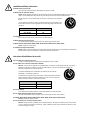
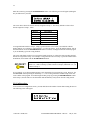
The voltage selector is a round switch located next to the A/C power input connector which looks
like this:
Using a straight slot screwdriver or small coin, rotate the selector to the correct position so that
the arrow lines up with 110 or 220 as appropriate for local power line voltage as indicated in the
chart below:
Local A/C Voltage
Voltage Selector Setting
110 ~ 120 VAC
110
220 ~ 240 VAC
220
For all Models:
No serviceable parts inside the unit. Refer service to a qualified technician.
For Models with Internal or External Fuses:
For continued protection against fire hazard, replace only with same type and rating of fuse.
For IN2001 / IN3234 / IN3236 / IN3502 / IN3504 / IN3506 / IN3562 / IN3564 / IN3566 / IN3572 / IN3574 / IN3576:
Caution: Double pole / neutral fusing.
For all Models with Integral Lithium Battery:
Caution: Danger of explosion if battery is incorrectly replaced. Replace only with the same or equivalent type recommended by
the manufacturer. Dispose of used batteries according to the manufacturer’s instructions.
Instructions d’installation et de sécurité
Pour les modèles sans interrupteur de courant:
La prise de courant d’alimentation sera installé près de l’équipement et sera accessible.
Pour les modèles avec un sélecteur d’alimentation 110V/220V:
Attention: Avant de connecter l’appareil au circuit d’alimentation, le sélecteur de courant doit être positionné sur la sélection
appropriée correspondant au voltage du circuit de courant alternatif local. Une mauvaise sélection peut engendrer des
dommages à l’appareil et créer un danger d’incendie.
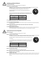
Le sélecteur d’alimentation est un commutateur rond positionné près du connecteur
d’alimentation. Il se représente comme suit:
A l’aide d’un tourne-vis plat ou d’une pièce de monnaie, le sélecteur peut être tourné dans la
position adéquate en veillaut que la flèche corresponde avec 110 ou 220, en fonction de la
valeur du circuit de courant local. (Voir tableau ci-dessous)
Circuit local AC
Position Sélecteur
110 ~ 120 VAC
110
220 ~ 240 VAC
220
Pour tout les modèles:
Pas de composants à entretenir à l’intérieur. Confiez toute réparation à un technicien qualifié.
Pour les modèles équipés de fusibles internes ou externes:
Afin d’éviter tout danger d’incendie, ne remplacer qu’avec le même type et la même valeur de fusible.
Pour IN2001 / IN3234 / IN3236 / IN3502 / IN3504 / IN3506 / IN3562 / IN3564 / IN3566 / IN3572 / IN3574 / IN3576:
Attention: Double pôle / fusible au neutre.
Pour tout les modèles avec une batterie au lithium interne:
Attention: Danger d’explosion si la batterie est incorrectement remplacée. Ne remplacez la batterie qu’avec le même modèle,
ou avec un modèle recommandé par le constructeur. Traitez les batteries usagées selon les instructions du fabricant, ou selon
les normes écologiques en viguer.
Installations und Sicherheitshinweise
Für Geräte ohne Netzschalter:
Die Netzsteckdose soll in de Nähe des Gerätes installiert und frei zugänglich sein.
Für Geräte mit 110 / 220V Spannungswähler:
Achtung: Bevor Sie dem Gerät Spann ung zuführen, muß der Spannungswähler entsprechend der Spannung des lokalen
Wechselspannungsnetzes eingestellt werden. Die falsche Stellung des Spannungswählers
kann eine Beschädigung des Gerätes und möglicherweise ein Feuer verursachen.
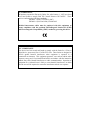
Der Spannungswähler ist ein runder Schalter in der Nähe der Netzeingangsbuchse mit
folgendem Aussehen:
Drehen Sie den Wähler mit einem normalen Schraubenzieher oder einer kleinen Münze so, daß
der Pfeil auf die 110 oder 220 zeigt, entsprechend der Spannung Ihr es lokalen Netzes wie hier
angezeigt:
Lokale Netzwechselspannung
110 ~ 120 V
Stellung des
Spannungswählers
110
220 ~ 240 V
220
Für alle Geräte:
Keine Wartung innerhalb des Gerätes notwendig. Reparaturen nur durch einen Fachmann!
Für Geräte mit interner oder externer Sicherung:
Für dauernden Schutz gegen Feuergefahr darf die Sicherung nur gegen eine andere gleichen Typs und gleicher Nennleistung
ausgewechselt werden.
Für IN2001 / IN3234 / IN3236 / IN3502 / IN3504 / IN3506 / IN3562 / IN3564 / IN3566 / IN3572 / IN3574 / IN3576:
Achtung: Allpolige Absicherung
Für alle Geräte mit eingebauter Lithium Batterie:
Achtung: Explosionsgefahr bei falschem Batterieeinsatz. Batterie nur erstzen durch den gleichen oder entsprechenden Typ
wie vom Hersteller empfohlen. Entsorgung verbrauchter Batterien nur nach den Anweisungen des Herstellers.
Instalacion E Instrucciones de Seguridad
Modelos Sin Interruptor:
La conexión debe ser instalada cerca del equipo y debe ser accesible.
Modelos con Selector de Voltaje de 110/220V:
Precaución: Antes de operar esta unidad, el selector de voltaje debe instalarse de forma que corresponda a la linea de voltaje
local. Instalación inadecuada del selector de voltaje puede causar daño a la unidad y originar un incendio.
El selector de voltaje es un cambia vía redondo localizado cerca de la conexión electrica, como se
ve en el dibujo:
Use un destornillador comun o una moneda pequeña, mueva el selector a la posición correcta, de
forma que las flechas indiquen 110 o 220 de acuerdo con el voltaje local, como esta indicado a
continuación.
Voltaje Local A/C
Selector de Voltaje
110 ~ 120 VAC
110
220 ~ 240 VAC
220
Para Todos Los Modelos:
Dentro de la unidad , no hay partes para reparar. Llame un tecnico calificado.
Modelos con Fusibles Internos o Externos:
Para prevenir un incendio, reemplace solo con el mismo tipo de fusible.
Modelos IN2001 / IN3234 / IN3236 / IN3502 / IN3504 / IN3506 / IN3562 / IN3564 / IN3566 / IN3572 / IN3574 / IN3576:
Precaución: Double Polo / Fusible Neutral.
Modelos con Bateria de Lithiun Interna:
Precaución: Peligro de explosión si la batería es reemplacada incorrectamente. Reemplace solamente con la misma clase de
batería, o una equivalente recomendada por el fabricante. Deseche las baterías usadas de acuerdo con las instrucciones del
fabricante.
CE COMPLIANCE
All products exported to Europe by Inline, Inc. after January 1, 1997 have been
tested and found to comply with EU Council Directive 89/336/EEC. These
devices conform to the following standards:
EN50081-1 (1991), EN55022 (1987)
EN50082-1 (1992 and 1994), EN60950-92
Shielded interconnect cables must be employed with this equipment to
ensure compliance with the pertinent Electromagnetic Interference (EMI)
and Electromagnetic Compatibility (EMC) standards governing this device.
FCC COMPLIANCE
This device has been tested and found to comply with the limits for a Class A
digital device, pursuant to Part 15 of the FCC rules. These limits are designed to
provide against harmful interference when equipment is operated in a
commercial environment. This equipment generates, uses and can radiate radio
frequency energy and, if not installed and used in accordance with the instruction
manual, may cause harmful interference to radio communications. Operation of
equipment in a residential area is likely to cause harmful interference, in which
case the user will be required to correct the interference at their own expense.
TABLE OF CONTENTS
Product Overview...................................................................................................................................... 1
Description........................................................................................................................................ 1
Fixed Configuration vs. Reconfigurable Switchers........................................................................... 1
Model Numbers ................................................................................................................................ 1
Front Panel Controls................................................................................................................................. 2
Switching - Connecting Inputs and Outputs (Front Panel) ................................................................... 3
Multiple Group Switching ................................................................................................................ 4
Saving and Recalling Setup Memories..................................................................................................... 5
Saving as Setup Memory .................................................................................................................. 5
Recalling a Setup Memory................................................................................................................ 6
Front Panel Menus .................................................................................................................................... 6
Selection Between PATH Config and MAIN MENU Sections ........................................................ 6
PATH Mapping ................................................................................................................................ 7
Group Mapping................................................................................................................................. 8
RGB Delay........................................................................................................................................ 9
LCD Contrast Adjust ...................................................................................................................... 10
RS-232 BAUD Rate........................................................................................................................ 10
COMMAND Code.......................................................................................................................... 11
Show SYSTEM Info ....................................................................................................................... 12
Power-On Adjustments........................................................................................................................... 13
Reset to Factory Default ................................................................................................................. 13
Board Configuration ....................................................................................................................... 13
I/O Configuration............................................................................................................................ 14
Using RS-232 Control.............................................................................................................................. 16
Communication Protocol ................................................................................................................ 16
Protocol Structure ........................................................................................................................... 16
Controlling Multiple INLINE Products .......................................................................................... 17
RS-232 Port Pin-outs ...................................................................................................................... 17
Protocol List ................................................................................................................................... 18
Specifications ........................................................................................................................................... 19
Warranty.................................................................................................................................................. 20
1
PRODUCT OVERVIEW
Description:
The PATHFINDER series switchers are designed to route multiple RGB and audio signals to multiple
output devices. A typical installation may involve computers, monitors, large screen data projectors, VCR’s
and video cameras. PATHFINDER series switchers are commonly installed in board rooms, training
centers, monitoring facilities, simulation systems and any other installation requiring comprehensive routing
over multiple video and audio sources. PATHFINDER switchers are also integrated into rental and staging
A/V systems for live presentations and shows.
Fixed Configuration vs. Reconfigurable Switchers
The PATHFINDER series switchers are available in two basic varieties: Fixed and Reconfigurable.
FIXED CONFIGURATION SWITCHERS
Fixed configuration switchers have a pre-determined number of input and output ports. For example, an
IN61204 is a fixed RGBS and stereo audio matrix switcher with a maximum of 12 input ports and 4 output
ports. If fewer ports than the maximum ports are going to be used, the unit can be set as a 10 in, 3 out, for
example, but could not be set for a 10 in, 6 out.
RECONFIGURABLE SWITCHERS
Re-configurable switchers offer flexibility in the number of input and output ports. The unit has a set
number of ports, and these can be configured by the user for any combination of input and output ports as
long as the total number does not exceed that available. For example, an IN60016 is a re-configurable
RGBS and stereo audio matrix switcher with 16 ports. The unit can be set for any combination of inputs
and outputs as long as (# input ports + # output ports ≤ 16). Thus, the unit could be set as a 14 x 2, 2 x 14,
8 x 8, 10 x 4, etc.
Model Numbers
The model number of your unit denotes its type and configuration. The IN50000 series are composite video
and stereo audio matrix switchers. The IN60000 series are RGBS and stereo audio matrix switchers, while
the IN60000G series are RGBS matrix switchers (no audio).
The last four digits of the model number designate the number of input and output ports. The following
table lists some model numbers and there descriptions as examples:
Model #
Description
IN50804
8 in, 4 out video and stereo audio switcher
IN50016
16 port re-configurable video and stereo audio switcher
IN61204
12 in, 4 out RGBS and stereo audio switcher
IN60808G
8 in, 8 out RGBS switcher
IN60016
16 port re-configurable RGBS and stereo audio
switcher
IN60012G
12 port re-configurable RGBS switcher
1995-1997 - INLINE, INC
PATHFINDER OPERATION MANUAL - REV2.1A
May 19, 1997
2
FRONT PANEL CONTROLS
SCROLL UP & DOWN: Scrolls through options available in various menu levels.
SAVE/RECALL:
Saves or Recalls setup memories of the PATHFINDER. Also saves setti9ngs for
various menus.
MENU: ............................ Changes menus and exits operations.
ENTER/SELECT: .......... Confirms or selects an operation.
NEXT:.............................. Steps through menu items and/or options available in various menus.
1, 2, 3, 4, 5, 6, 7, 8, 9, 0: .. These buttons are used to enter numbers.
STAND-BY: .................... (Not pictured) This button enters and exits the Stand-by mode.
(Note: The LED stays on all the time.)
1995-1997 - INLINE, INC
PATHFINDER OPERATION MANUAL - REV2.1A
May 19, 1997
3
SWITCHING - CONNECTING INPUTS AND OUTPUTS (FRONT PANEL)
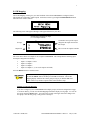
The switching menu is called the PATH Config menu, and it functions as follows:
Use the Up and Down Scroll button
to select the output you would like
to change.
Use the number buttons to enter the number
of the input you would like to connect to the
selected output. It is always best to enter a
two digit number, such as 03 or 12.
Use the ENTER/SELECT button to
confirm a switch. This button executes the
switch selected.
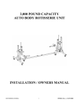
The diagram above shows the LCD readout for the PATH Config menu. The actual readout will vary
depending on the number of inputs and outputs your unit has. The bottom line of the LCD display shown
above, INxx/yy>OUTjj/kk," reads as follows: Input xx of yy is connected to output jj of kk, where:
Ga:
The selected group is Group a. a ranges from 1 to 6. (see Board Configuration on page 13 for
Sb:
more details.)
The selected setup memory is b. b ranges from 1 to 8 (see Saving and Recalling Setup
xx:
yy:
jj:
kk:
Memories on page 5 for more details.)
The selected input.
The total number of inputs available.
The selected output.
The total number of outputs available.
1995-1997 - INLINE, INC
PATHFINDER OPERATION MANUAL - REV2.1A
May 19, 1997
4
Step 1: Select the Output:
To make a connection between an input and an output, you scroll through each available output and then
assign it an input. This may seem backwards at first, but when you think about it more carefully, you will
see that it is not. A routing matrix switcher can have one input going to several outputs simultaneously, but
an output can only have one input (unless you want to see multiple image on top of each other). Therefore,
it is more logical to select the output and then the input you would like to connect to that output.
Use the Up and Down scroll buttons to select the output, jj, you would like to switch. The Down button
selects the next output until you reach kk. After kk, the output selected begins at 01 again. The Up button
selects the previous output.
Step 2: Select the Input:
Once the desired output is selected, you need to enter the number of the input you would like to connect to
that output. You will notice that there is a blinking cursor over the input xx that is currently connected to
output jj. The blinking cursor indicates that you can change this by using the number buttons to enter the
desired input. It is always best to enter a two digit number, such as 03, 12, or 05. The number you can
enter ranges from 00 to yy (Actually, you can enter any number from 00 to 99, but the switch will not
execute if the number is greater than yy).
To blank an output, connect input 00 to that output. This disconnects the selected
output, that is no input is connected to that output.
It is important to note that a switch is not executed until the ENTER/SELECT button is pushed.
Therefore, if you punch in the wrong number, do not worry. All you have to do is re-enter the two digit
number of the input you would like to connect to the selected output.
Step 3: Execute the Switch:
Now that you have selected the output and the input you want to connect to that output, you need to push
the ENTER/SELECT button to execute the switch. This step is very important; otherwise, as soon as you
select another output, the selected connection will be erased.
Multiple Group Switching:
If you have configured your PATHFINDER with multiple groups (see Board Configuration on page 13 for
more details), you will need to select the group prior to making a switch. In the previous diagram, Ga
shows the selected group number. When a switch is made with the front panel, the input to output
connection is made to the boards in the current group only.
The NEXT button is used to select the next group. After the last group is reached, it returns to Group 1
(G1).
1995-1997 - INLINE, INC
PATHFINDER OPERATION MANUAL - REV2.1A
May 19, 1997
5
SAVING AND RECALLING SETUP MEMORIES
The PATHFINDER can store and recall up to 8 setup memories. A memory stores input to output
connection information, and when recalled, executes all of the switch connections.
When the PATHFINDER is turned on, it uses setup #1 as the default, and this cannot
be changed. If you plan on turning off the PATHFINDER, make certain to store the
initial settings in Setup #1.
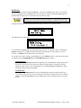
Saving a Setup Memory:
To save a memory configuration, make the desired input to output connections for all groups and then push
the SAVE/RECALL button. The following screen will appear (Note: Changes must be made in order for
the PATHFINDER to prompt you if you would like to Save the changes):
You have three options to choose from, with Sb showing the current Setup being used. Press the
appropriate number button as follows:
1)Y:
Pressing the number 1 button saves the input to output connection information to Setup #b.
2)N:
Pressing the number 2 button tells the PATHFINDER that you do not want to save the changes. As
the SAVE/RECALL button is a single button for two functions (Save and Recall), the unit enters the
Recall menu to allow you to recall a Setup memory (see Recalling a Setup Memory on page 6 for
more details).
3)SETUP#:
Pressing the number 3 button allows you to save the input to output connection information to any
Setup memory. The following screen will appear:
The flashing cursor over Setup:b shows that you can change this with the number buttons. Press
the number button of the Setup# you would like to store this information to. Confirm this selection
by pressing the ENTER/SELECT button.
1995-1997 - INLINE, INC
PATHFINDER OPERATION MANUAL - REV2.1A
May 19, 1997
6
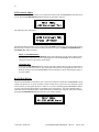
Recalling a Setup Memory:
To recall a memory configuration, push the SAVE/RECALL button. One of two screens will appear
depending on whether you made any input to output connection changes.
No Changes Made:
If no changes were made, the unit will prompt you to select a memory setup as follows:
The unit shows you the current setup #b, with a blinking cursor over the number. The blinking
cursor indicates that you can change this by using the number buttons to enter the desired setup#. As
there are eight setup memories, the PATHFINDER will only accept a number from 1 to 8. Confirm
the number of the setup# you desire by pressing the ENTER/SELECT button.
Changes Made:
If you made any changes in the input to output connection configuration, the unit will first prompt
you if you would like to save the changes (see Saving a Setup Memory on page 5 for more details).
After pressing the number 2 button, the PATHFINDER will access the Recall Setup menu as shown
above in the No Changes Made section.
FRONT PANEL MENUS
The PATHFINDER front panel has two main sections for control: The PATH Config section and the
MAIN MENU section, the latter being divided into seven sections. The MAIN Menu and its sections are
described below:
Selection Between the PATH Config and MAIN MENU Sections:
Pressing the MENU button alternates between the PATH Config and MAIN MENU sections. After power
up, the PATHFINDER enters the PATH Config menu which allows you to make switch connections. By
pressing the MENU button, the unit will switch to the MAIN MENU section, and the screen will look as
follows:
PATH Mapping is the first available section, followed by GROUP Mapping, RGB Delay, LCD Contrast
Adj, RS-232 BAUD Rate, COMMAND Code, and Show SYSTEM Info. To scroll through the sections of
the MAIN MENU, use the Up and Down Scroll buttons or the NEXT button. To enter one of the sections,
push the ENTER/SELECT button, and that section’s main screen will appear. A description of each of the
seven sections follows:
1995-1997 - INLINE, INC
PATHFINDER OPERATION MANUAL - REV2.1A
May 19, 1997
7
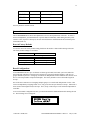
PATH Mapping:
The PATH Mapping section gives you visual feedback of how the PATHFINDER is configured, that is
which inputs are connected to which outputs. Enter this sections by pressing the ENTER/SELECT button
when the screen reads as follows:
The following screen will appear (although it will appear different for your unit):
A blank square designates no input
(i.e.: The output is blank)
The number on top of the output
designates the input connected to
that output.
Group #
Output row
This row lists the outputs available.
The screen above shows an example for an 8 output PATHFINDER. The example has the following input
and output configuration for Group 1:
•
•
•
•
Input 1 to Outputs 1 and 2
Input 4 to Output 5
Input 2 to Output 6
Input 0 to Outputs 3, 4, 7 & 8 (The outputs are blank)
Press the MENU button to exit this section.
You can view the PATH Mapping display while in the PATH Config menu. Press
and hold the MENU button, and then press the UP scroll button. The PATH
Mapping display will show the current group as long as you hold the UP scroll
button. This is very useful as a quick check of the switcher’s setup.
Multiple Group Path Mapping:
If you have configured your PATHFINDER with multiple groups (see Board Configuration on page
13 for more details), you can view the Path Mapping information display for all groups. To view the
next group, push the NEXT button. You will see the Group# in the upper left corner change to the
next group. After the last group, it will go back to Group# 1.
1995-1997 - INLINE, INC
PATHFINDER OPERATION MANUAL - REV2.1A
May 19, 1997
8
Group Mapping:
The GROUP Mapping section gives you visual feedback of which boards are in which group (see Board
Configuration on page 13 for more details). Enter this section by pressing the ENTER/SELECT button
when the screen reads as follows:
The following screen will appear (although it may appear different for your unit):
The number on top of the board
designates the group that board is
in.
Group Row
Board Row
This row lists the boards available
The bottom row of numbers lists the boards available on the unit, where boards 1 - 6 are as follows:
Board #
1
2
3
4
5
6
Description
Red Video Board
Green Video Board
Blue Video Board
Sync Board
Audio Left Board
Audio Right Board
The screen above shows an example of a PATHFINDER set with two groups. Group 1 contains boards 1,
2, 3 and 4 (Red, Green, Blue and Sync), while Group 2 contains boards 5 and 6 (Audio Left and Right). By
assigning the video and audio boards in two different groups, you can switch them independent of each
other. You can "break away" the audio from the video.
Press the MENU button to exit this section.
1995-1997 - INLINE, INC
PATHFINDER OPERATION MANUAL - REV2.1A
May 19, 1997
9
RGB Delay:
RGB Delay is a key feature of the PATHFINDER. It provides an adjustable delay time (0 to 6 seconds)
between switching the sync and RGB boards. The sync signal is connected first and the RGB signals are
blanked while the display device is allowed to lock up to the new signal.
RGB delay prevents the display device from showing re-sizing and other spurious
on-screen effects which often occur while the display is adjusting to the new signal.
Enter this section by pressing the ENTER/SELECT button when the screen reads as follows:
The following screen will appear:
At 0.0 Seconds, the RGB and the sync will switch at the same time. To adjust the delay, use the UP and
DOWN scroll buttons. The UP scroll button will increase the delay up to 6.0 Seconds in 0.5 second
intervals. The DOWN scroll button decreases the delay time.
To exit this section with no change to the RGB Delay, press the MENU button. To activate the delay time
you entered, press the ENTER/SELECT or SAVE/RECALL button as follows:
ENTER/SELECT:
Pressing the ENTER/SELECT button will temporarily store the RGB Delay setting until the power
is turned off. This feature can be used to try different settings without overwriting the existing
setting previously stored. Upon re-applying power to the PATHFINDER, the RGB Delay setting
will return to its previously saved setting.
SAVE/RECALL:
Pressing the SAVE/RECALL button will save the RGB Delay setting in memory and will use it
every time the unit is powered on. This setting will remain until you tell the unit to Save a different
setting or reset the PATHFINDER to Factory Default (see Power On Settings on page 13 for more
details).
1995-1997 - INLINE, INC
PATHFINDER OPERATION MANUAL - REV2.1A
May 19, 1997
10
LCD Contrast Adjust:
The LCD Contrast Adj. section allows you to adjust the contrast of the PATHFINDER’s front panel LCD
screen. Press the ENTER/SELECT button when the screen reads as follows:
The following screen will appear:
The UP Scroll button will increase the contrast while the DOWN Scroll button will decrease the contrast.
When you have set the LCD screen to the desired contrast level, press the MENU, ENTER/SELECT or
SAVE/RECALL button as follows:
MENU or ENTER/SELECT:
Pressing the MENU or ENTER/SELECT button will temporarily store the LCD Contrast setting
until the power is turned off. Upon re-applying power to the PATHFINDER, the LCD Contrast
setting will return to its previously saved setting.
SAVE/RECALL:
Pressing the SAVE/RECALL button will save the LCD Contrast setting in memory and will use it
every time the unit is powered on. This setting will remain until you re-program the unit to Save a
different setting or reset the PATHFINDER to Factory Default (see Power On Settings on page 13
for more details).
RS-232 BAUD Rate:
The RS-232 BAUD Rate section allows you to choose the baud rate at which the PATHFINDER’s remote
control port operates at. If you are not using a remote control device, such as a PC or a third party remote
control system, you can ignore this section. However, if you are controlling the PATHFINDER remotely,
you may need to change the baud rate to match that of the control device. The factory default setting is
1200 baud, and you can change this to 2400, 4800, 9600 or 19200 baud as required. Enter this section by
pressing the ENTER/SELECT button when the screen reads as follows:
1995-1997 - INLINE, INC
PATHFINDER OPERATION MANUAL - REV2.1A
May 19, 1997
11
The following screen will appear (although it may appear different for your unit if it is already set for a
baud rate other than 1200):
The asterisk, *, in the bottom right hand corner of the display indicates that this baud rate is currently
selected. To view the other rates available, press the NEXT button, and the baud rate will change to the
next highest rate, which would be 2400bps for this example. You will notice that there is no asterisk for
2400, as this in not the current baud rate the PATHFINDER is set to use. Pressing the NEXT button again
will increase the baud rate to 4800bps, then 9600bps, then 19200bps, and then back to
1200bps. When the desired baud rate is displayed, you can select it or exit with no change as follows:
MENU:
Pressing the MENU button exits this section with no change.
ENTER/SELECT:
Pressing the ENTER/SELECT button will temporarily store the Baud Rate setting until the power is
turned off. Upon re-applying power to the PATHFINDER, the Baud Rate will return to its
previously saved setting.
SAVE/RECALL:
Pressing the SAVE/RECALL button will save the Baud Rate setting in memory and will use it every
time the unit is powered on. This setting will remain until you re-program the unit to Save a different
setting or reset the PATHFINDER to Factory Default (see Power On Settings on page 13 for more
details).
COMMAND Code:
The COMMAND Code section allows you to choose the leading and ending characters of the actual
protocol which the PATHFINDER will respond to. By choosing different Command Codes for multiple
units, up to four PATHFINDERs can be controlled independently with one RS-232 serial port (Note: A RS232 distribution amplifier must be used.) If you are not using a remote control device, such as a PC or a
third party remote control system, you can ignore this section. Enter this section by pressing the
ENTER/SELECT button when the screen reads as follows:
1995-1997 - INLINE, INC
PATHFINDER OPERATION MANUAL - REV2.1A
May 19, 1997
12
The following screen will appear (although it may appear different for your unit if it is already set for a
different Command Code):
The asterisk in 1[]* indicates that this Command Code is currently selected,. To choose a different
Command Code, press the corresponding number button. For example, pressing the number 3 button will
place the asterisk in 3()*, choosing the parenthesis as the Command Code. When the desired Command
Code is chosen, you can select it or exit with no change as follows:
MENU:
Pressing the MENU button exits this section with no change.
ENTER/SELECT:
Pressing the ENTER/SELECT button will temporarily store the Command Code setting until the
power is turned off. Upon re-applying power to the PATHFINDER, the Command Code will return
to its previously saved setting.
SAVE/RECALL:
Pressing the SAVE/RECALL button will save the Command Code setting in memory and will use it
every time the unit is powered on. This setting will remain until you re-program the unit to Save a
different setting or reset the PATHFINDER to Factory Default (see Power On Settings on page 13
for more details).
Show SYSTEM Info:
The Show SYSTEM Info section displays information about your PATHFINDER. Enter this section by
pressing the ENTER/SELECT button when the screen reads as follows:
The following screen will appear (although it may appear different for your unit depending on its
configuration):
The screen above shows that the Firmware version of the unit is 2.0a, and the C/N# tells us that it is a 12 in,
4 out unit. The Configuration Number, C/N#, describes the unit and is set at the factory. Some examples
are as follows:
1995-1997 - INLINE, INC
PATHFINDER OPERATION MANUAL - REV2.1A
May 19, 1997
13
C/N#
Model #
Description
06140101
IN60016
16 Port Reconfigurable Switcher
06001204
IN61204
12 in, 4 out Fixed Switcher
06000808
IN60808
8 in, 8 out Fixed Switcher
Press any button to exit this section.
POWER-ON ADJUSTMENTS
The PATHFINDER utilizes Power-On adjustments to access critical parameters of the unit. To access a
Power-On adjustment, you must hold down a specific button continuously while turning the unit’s power
switch to "ON" (if power is already on, the user can hold down the indicated button and switch the power
off and then back on.)
Reset to Factory Default:
To reset the unit to the factory default setting, hold down the number 1 button while turning on the unit.
The factory default settings are as follows:
RGB Delay:
LCD Contrast:
RS-232 Baud Rate
Command Code:
Board Configuration:
I/O Configuration:
0.0 seconds
Normal setting
1200
[]
Boards 1 - 6 in Group 1
1 input active, 1 output active
Board Configuration:
A PATHFINDER can have up to six boards: red board, green board, blue board, sync board, audio left
board and audio right board. Boards can be assigned as a group and controlled together, with up to six
groups definable by the user. Each group is treated as an independent switcher within the unit, and can even
have its own unique number of Inputs and Outputs. The factory default is to have all boards assigned to
Group 1.
One of the most common uses of assigning multiple groups is to switch audio independent of video. This
can be accomplished by assigning boards 1 to 4 (red, green, blue and sync boards) to Group 1, and boards 5
and 6 (audio left and right boards) to Group 2. Now, Group 1 and Group 2 can be switched independent of
each other.
To access the Board Configuration section, you must hold down the number 2 button while turning the unit
on. The following screen will appear:
1995-1997 - INLINE, INC
PATHFINDER OPERATION MANUAL - REV2.1A
May 19, 1997
14
Enter this section by pressing the ENTER/SELECT button. The following screen will appear (although it
may be different for your unit):
The screen above shows the boards currently assigned to Group 1. The factory default is to have all six
boards assigned to Group 1, where:
Board #
1
2
3
4
5
6
Description
Red Video board
Green Video board
Blue Video board
Sync board
Left Audio board
Right Audio board
To assign different boards to Group 1, simply type the numbers of the boards you would like with the
number buttons. For example, to assign boards 1, 2, 3 and 4 to Group 1, press the number button 1, then 2,
then 3 and then 4. Press the ENTER/SELECT button to confirm, or simply turn the unit off and try again
if you accidentally type in the wrong numbers.
The screen will change to allow you to assign the boards for Group 2. Follow the same procedure until all
boards are assigned to a Group. For example, to assign boards 5 and 6 to Group 2, press the number button
5 and then 6, and confirm with the ENTER/SELECT button.
Each board can be assigned to only one Group. For example, you cannot assign
boards 1, 2, 3 and 4 to Group 1; boards 5 and 6 to Group 2; and boards 1, 2, 3, 4,
5 and 6 to Group 3.
In our example, we are done assigning groups as all 6 boards have been assigned to a group. However, the
PATHFINDER will still prompt you for Groups 3 - 6. Do not assign boards to another Group as this will
cause conflict in the program. Proceed through all other groups by pressing the ENTER/SELECT button.
After Group 6, the unit will save the information and automatically send you into the I/O Config section.
I/O Configuration:
To access the I/O Configuration section, you must hold down the number 3 button while turning the unit on.
The following screen will appear:
1995-1997 - INLINE, INC
PATHFINDER OPERATION MANUAL - REV2.1A
May 19, 1997
15
Enter this section by pressing the ENTER/SELECT button. The following screen will appear (although it
may be different for your unit):
G1 indicates you are setting the I/O configuration for
Group 1. The current setting is 1 active output out of a
possible 4 outputs.
Exit With No Change:
You can Exit with no change at any time by pressing the MENU button or simply turning the unit off
Step 1: Select the Number of Outputs:
Use the Keypad to enter a two digit number corresponding to the number of desired outputs. For example,
to set 4 outputs, press the number buttons 04. If you accidentally type in the wrong number, simply re-type
the two digit number.
Confirm your entry by pressing the ENTER/SELECT button. The following screen will appear (although
it may be different for your unit):
G1 indicates you are setting the I/O configuration
for Group 1. The current setting is 1 active input
out of a possible 12 inputs.
Step 2: Select the Number of Inputs:
Use the Keypad to enter a two digit number corresponding to the number of desired inputs. For example, to
set 12 inputs, press the number buttons 12. If you accidentally type in the wrong number, simply re-type the
two digit number.
Confirm your entry by pressing the ENTER/SELECT button.
Step 3: Other Groups:
If you have configured your unit with more than 1 Group, proceed with assigning the number of Inputs and
Outputs for the other groups as in steps 1 and 2.
When you reach an I/O Configuration for a Group that does not have any boards assigned to it, the screen
will read Undefined. Proceed through all other groups by pressing the ENTER/SELECT button.
After Group 6, the screen will say DONE and the PATHFINDER will save the information. The unit will
then reset itself and go into the PATH Config section.
1995-1997 - INLINE, INC
PATHFINDER OPERATION MANUAL - REV2.1A
May 19, 1997
16
USING RS-232 CONTROL
The PATHFINDER has two 9 pin RS-232 ports which will accept serial commands from a control system,
computer serial port, or any other device capable of sending out serial ASCII commands at compatible baud
rates. All switching, configuration and set-up parameters can be controlled using RS-232 commands. A
few functions cannot be accomplished from the front control panel and are available only through RS-232
control:
Load and Switch All Output Ports
Executive Mode: Disable Access to Configuration Menus from the Front Control Panel
Getting Firmware Information on the Microcontroller
Details on the commands above and a complete listing of RS-232 codes is included on pages 18 and 19.
Communication Protocol:
The baud rate that the PATHFINDER operates is selectable from 1200 to 19,200 baud (see RS-232 BAUD
Rate on page 10). Communication parameters are as follows:
1200 baud (Factory default setting)
No Parity
8 data bits
1 stop bit
Protocol Structure:
All commands sent to the unit must contain a leading character, the actual command, and an ending
character. Each command must be completely executed by the PATHFINDER before it will accept a new
command. When a command is executed, the unit provides the response [OK] to indicate that the command
was received and executed. Do not sent a new command until the [OK] is received, otherwise there may be
a conflict. The response [ERR] indicates that there was a problem and the command was not executed.
The PATHFINDER can recognize one of four sets of leading and ending characters, also called the
Command Codes. These are:
[ ]
{ }
( )
< >. The factory default for the Command
Code is [ ]. The Command code can be changed from the Front Control Panel (see Command Code on
page 11)
A complete command string consists of:
[
The leading character
CALL2
The actual command.
]
The ending character
Some sample command codes follow:
[CALL1]
Recall setup memory 1
[RGB3.0] Set RGB Delay to 3 seconds
1995-1997 - INLINE, INC
PATHFINDER OPERATION MANUAL - REV2.1A
May 19, 1997
17
Controlling Multiple INLINE Products:
Many INLINE products such as the PATHFINDER, the IN1222/IN1240/IN1422 scan doublers and the
IN1510/IN1540/IN1710 decoders use similar communication protocol structures. By setting each unit to a
different Command Code, up to four INLINE products can be controlled independently by a single RS-232
serial control port (Note: A RS-232 distribution amplifier may be required.)
RS-232 Port Pin-outs:
There are two RS-232 ports on the PATHFINDER. There is a 9 pin D female connector on the front of the
unit, and a 9 pin D male connector on the back. Only one port can be used at a time as both ports are wired
in parallel. If you are using a port to loop out to another device, a RS-232 buffer may be required.
Both ports have the same pin-outs as follows:
Pin #
2
3
5
Signal
Receive
Transmit
Ground
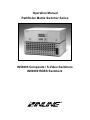
When using a PC to control the PATHFINDER, you may need to tie certain pins together on the computer
side to activate the serial port. If these pins are not tied together, the serial port will not be active, so no
strings will be sent. The following diagram shows the pins that need to be tied together:
1995-1997 - INLINE, INC
PATHFINDER OPERATION MANUAL - REV2.1A
May 19, 1997
18
COMMAND1
ACI3
*
ACI4
*
ACI5
*
ACI6
*
ACI7
*
CALLs
SAVEs
SAVE0
PTgOmmInn
Lgo1o2o3 . . .
SW
RGBx.x
GgBb1b2b3 . . .
IOgOoIi
FP
FP0
*
*
COMMAND1
1
*
DESCRIPTION
Set to 1200 baud rate, default setting
Set to 2400 baud rate
Set to 4800 baud rate
Set to 9600 baud rate
Set to 19200 baud rate
Recall configuration from SETUPs
s: 1 byte ASCII code, ranges from 1 - 8
Save current configuration to SETUPs
s: 1 byte ASCII code, ranges from 1 - 8
Save Global setting(s)
Execute a switch. Connect Input nn to Output mm for Group g.
g:
Group #, a 1 byte ASCII code, ranges from 1 - 6
nn: Input #, a 2 byte ASCII code. If nn = 00, no input is selected,
resulting in a blank output.
mm: Output #, a 2 byte ASCII code
Exp: "[PT1O08I04]"
Connect Input #4 to Output #8 for the boards in Group 1
Load a new path for Group g. The switch is not executed until the "[SW]"
command is sent.
on: 2 byte ASCII code representing the Input# to be connected to output
#n.
Exp1: "[L104050003]
Load a new path for Group #1 as follows: Input #4 to Output #1, Input
#5 to Output #2, Input #0 to Output #3 (disconnect), and Input #3 to
Output #4.
Exp2: "[L1020101,L2101107]"
Load a new path for Group #1 as follows: Input #2 to Output #1, Input
#1 to Output #2, Input #1 to Output #3.
Load a new path for Group #2 as follows: Input #10 to Output #1,
Input #11 to Output #2, Input #7 to Output #3
Execute all switch connections as defined by the L command.
Set RGB delay to x.x seconds. x.x: ranges from 0.0 to 6.5 in 0.5 second
intervals.
Exp: "[RGB3.5]" Set RGB delay to 3.5 seconds.
Note: Normally, the RGB delay is only used when boards 1, 2, 3 & 4 are all
in the same group. However, the RS-232 command sets the unit so that it
ignores this fact. Therefore, if you do not assign boards 1, 2, 3 & 4 to the
same group, you MUST set the RGB delay to 0.0 seconds to ensure proper
switching (with no delays.)
Set boards b1, b2, b3 . . . to group g
Exp: "[G1B1234]" Define Group 1 as boards 1, 2, 3 & 4
Set input/output configuration for group g
Exp: "[IO1O04I12]" Define Group 1 input/output configuration as 4
outputs and 12 inputs.
Enable and disable the front panel operation (toggle between FP0 and FP1.
Disable the front panel operation (put the unit into the Stand-by mode). All
front panel buttons are disabled, except for the Stand-by button, and the
backlight of the LCD screen is turned off.
DESCRIPTION
RESPONSE
[OK]
[OK]
[OK]
[OK]
[OK]
[OK]
[OK]
[OK]
[OK]
[OK]
[OK]
[OK]
[OK]
[OK]
[OK]
[OK]
RESPONSE
Leading and ending codes not shown for clarity.
Global Settings (Save with SAVE0 Command)
1995-1997 - INLINE, INC
PATHFINDER OPERATION MANUAL - REV2.1A
May 19, 1997
19
FP1
*
FP2
*
INF0
INF1
1
*
Enable the front panel operation (take the unit out of the Stand-by mode and
Executive mode).
Executive mode. Disable access to configuration menus from the front panel
(Path Config, RGB delay, RS-232 baud rate, and Command code).
Get the firmware version
Get the Configuration Number (C/N).
[OK]
[OK]
[PATHFINDER V2.0a]
Varies with model #
Leading and ending codes not shown for clarity.
Global Settings (Save with SAVE0 Command)
SPECIFICATIONS
RGBS Input:
Connectors
Impedance
RGB Level
Sync Level
Coupling
Audio Input
Connectors
Impedance
Level
RGBS Output:
Connectors
Impedance
Bandwidth
RGB Gain
Sync Output:
Audio Output:
Audio Connectors
Audio Impedance
Gain:
Bandwidth:
General:
Power:
Power Consumption:
Size:
Weight:
1995-1997 - INLINE, INC
(4) Female BNC
75 Ohms
0.7 Vp-p Nominal, 2 Vp-p maximum
5 V maximum
DC coupled. Any input signal DC offset should be limited to ±0.5 VDC to allow for
an acceptable signal swing without distortion.
(2) Female RCA
620 Ohms
Line Level
(4) Female BNC
75 Ohms
120 MHz
1.0 ± 5%
1.0 ± 5% Gain into 75 Ohms, 4 V maximum
(2) Female RCA
620 Ohms
1.0 ± 5%
50 MHz
96 - 260 VAC, 40 to 60 Hz
35W Max.
17"W x 11.5"D x 5.25"H
20 lbs.
PATHFINDER OPERATION MANUAL - REV2.1A
May 19, 1997
20
WARRANTY
♦
INLINE warrants the equipment it manufactures to be free from defects in materials and
workmanship.
♦
If equipment fails because of such defects and INLINE is notified within two (2) years from the
date of shipment, INLINE will, at its option, repair or replace the equipment at its plant, provided
that the equipment has not been subjected to mechanical, electrical, or other abuse or
modifications.
♦
Equipment that fails under conditions other than those covered will be repaired at the current price
of parts and labor in effect at the time of repair. Such repairs are warranted for ninety (90) days
from the day of re-shipment to the Buyer.
♦
This warranty is in lieu of all other warranties expressed or implied, including without
limitation, any implied warranty or merchantibility or fitness for any particular purpose, all
of which are expressly disclaimed.
The information in this manual has been carefully checked and is believed to be accurate. However,
Inline, Inc. assumes no responsibility for any inaccuracies that may be contained in this manual. In no
event will Inline, Inc. be liable for direct, indirect, special, incidental, or consequential damages
resulting from any defect or omission in this manual, even if advised of the possibility of such
damages. The technical information contained herein regarding PATHFINDER features and
specifications is subject to change without notice.
All Rights Reserved © Copyright 1995-1997
© Inline, Inc. ♦ 22860 Savi Ranch Parkway ♦ Yorba Linda, CA 92887
(800) 882-7117
♦
1995-1997 - INLINE, INC
(714) 921-4100
♦
Fax (714) 921-4160
♦
www.inlineinc.com
PATHFINDER OPERATION MANUAL - REV2.1A
May 19, 1997