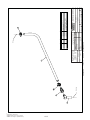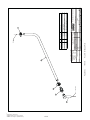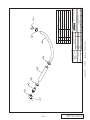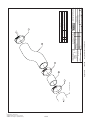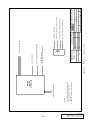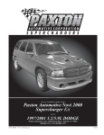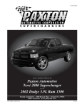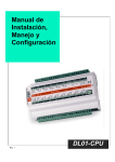
1
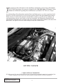
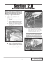
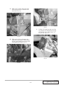
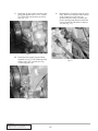
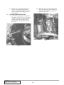
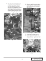
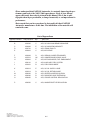
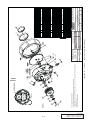
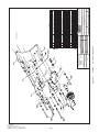
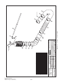
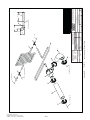
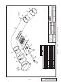
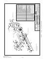
Kit # 1201210
S U P E R C H A R G E R S
Owners Installation Guide for the
Paxton Automotive
NOVI 2000 Supercharger
for the
1994-2001 Dodge
V-10 Truck
PAXTON Automotive . 1300 Beacon Place . Oxnard CA 93033
(888) 9-PAXTON . FAX (805) 247-0669
DP/N: 4800019 - Dodge V-10 v2.0
09/25/03
T
his manual provides information on the installation, maintenance and servicing of the Paxton
NOVI-2000 Supercharger kit expressly designed for the 1994-2001 Dodge V-10 truck. Contact
Paxton for information regarding these modifications at (805)604-1336 7:00 a.m.-3:30p.m.
PST.
An understanding of the information contained herein will help novices as well as experienced technicians to correctly install and receive the greatest possible benefit from their Paxton Supercharger.
When reference is made in this manual to a brand name, number or specific tool or technique, an
equivalent product may be used in place of the item mentioned. All information, illustrations and
specifications contained herein are based on the latest product information available at the time of the
publication. The right is reserved to make changes at any time without notice.
KIT P/N: 1201210
© 2003 PAXTON AUTOMOTIVE
All rights recerved. No parts of this publication may be reproduced, transmitted, transcrived, or translated into
another language in any form, by any means without written permission of Paxton Automotive.
P/N: 4800019
©2003 Paxton Automotive
All Rights Reserved, Intl. Copr. Secured
25SEP03 v2.0 Dodge V-10(4800019v2.0)
ii
TABLE OF CONTENTS
FOREWORD . . . . . . . . . . . . . . . . . . . . . . . . . . . . . . . . . . . . . . . . . . . . . . . . . . . . . . . . .2
TABLE OF CONTENTS . . . . . . . . . . . . . . . . . . . . . . . . . . . . . . . . . . . . . . . . . . . . . . . . .TC-I
1.0
INTRODUCTION . . . . . . . . . . . . . . . . . . . . . . . . . . . . . . . . . . . . . . . . . . . . . . . .1-1
2.0
INITIAL PREPARATION AND DISASSEMBLY . . . . . . . . . . . . . . . . . . . . . . . .2-1
3.0
SUPERCHARGER INSTALLATION AND ASSEMBLY . . . . . . . . . . . . . . . . . .3-1
4.0
ADDITIONAL INJECTOR CONTROLLER INSTALLATION. . . . . . . . . . . . . . .4-1
5.0
FINAL CHECK AND START-UP . . . . . . . . . . . . . . . . . . . . . . . . . . . . . . . . . . . . .5-1
APPENDICES
Appendix A
Appendix B
Appendix C
Appendix D
Appendix E
Appendix F
Appendix G
Appendix H
Appendix I
Appendix J
Appendix K
Appendix L
Appendix M
Appendix N
PARTS LIST . . . . . . . . . . . . . . . . . . . . . . . . . . . . . . . . . . . . . . . . . . . . .A-2
ASY, NOVI 2000 SUPERCHARGER . . . . . . . . . . . . . . . . . . . . . . . . . .A-3
ASY, SUPERCHARGER MOUNTING BRACKET . . . . . . . . . . . . . . .A-4
ASY, CRANK PULLEY . . . . . . . . . . . . . . . . . . . . . . . . . . . . . . . . . . . .A-5
ASY, AIR INTAKE . . . . . . . . . . . . . . . . . . . . . . . . . . . . . . . . . . . . . . . .A-6
ASY, AIR DISCHARGE . . . . . . . . . . . . . . . . . . . . . . . . . . . . . . . . . . . .A-7
ASY, COMPRESSOR BYPASS . . . . . . . . . . . . . . . . . . . . . . . . . . . . . . .A-8
ASY, SPRING LOADED TENSIONER . . . . . . . . . . . . . . . . . . . . . . . .A-9
ASY, AUXILIARY FUEL SYSTEM . . . . . . . . . . . . . . . . . . . . . . . . . . .A-10
ASY, FUEL ENRICHMENT . . . . . . . . . . . . . . . . . . . . . . . . . . . . . . . . .A-11
ASY, OIL SUPPLY AND RETURN . . . . . . . . . . . . . . . . . . . . . . . . . . . .A-12
ASY, HEATER HOSE RELOCATION . . . . . . . . . . . . . . . . . . . . . . . . .A-13
RADIATOR HOSE EXTENSION ASSEMBLY . . . . . . . . . . . . . . . . . . .A-14
ASY, WASHER BOTTLE RELOCATION . . . . . . . . . . . . . . . . . . . . . . .A-15
iii
P/N: 4800019
©2003 Paxton Automotive
All Rights Reserved, Intl. Copr. Secured
25SEP03 v2.0 Dodge V-10(4800019v2.0)
This Page Left Intentionally Blank
P/N: 4800019
©2003 Paxton Automotive
All Rights Reserved, Intl. Copr. Secured
25SEP03 v2.0 Dodge V-10(4800019v2.0)
iv
Section 1.0
INTRODUCTION
C
ongratulations! You have purchased the
finest street supercharger available for the
1994-2001 Dodge V-10 truck. The centerpiece of the kit is the highly efficient and reliable PAXTON NOVI-2000 supercharger - a
mechanically driven (by belt) centrifugal blower
(supercharger).
This kit comes with all of the parts you’ll need
for a successful installation. The operations
required have been grouped in order of
sequence. Photos and drawings accompany the
text, allowing quick orientation and parts identification.
Installation requires a selection of tools which
are listed in a table at the end of this section.
We also suggest that you obtain a Dodge truck
shop manual and become familiar with the
details of your car’s systems. Manuals may be
obtained from your local Dodge dealer or you
can order one from Helm Publications at (800)
782-4356.
For best results, follow the instructions closely
and in sequence. The average installation time
for this kit is 8-10 hours. Your actual installation
time will depend on skill level and working conditions. The estimate does not include time for
initial vehicle inspection, cleaning, fine tuning
or troubleshooting. Before even picking up a
wrench, read this entire manual. We are available for technical assistance at (805) 6041336, 7 AM-3:30 PM Pacific Time.
er any missing or mislabeled parts, please contact Paxton by phone for service.
***** WARNING *****
DO NOT attempt installation if any part(s)
are missing from this kit. Failure to contact
Paxton prior to beginning installation will
result in a charge for any missing parts.
Before starting the installation, we suggest your
engine and engine compartment be clean. You
can clean the engine and compartment with a
pressure washer (such as those used at self-serve
car washes) and a safe-for-aluminum
cleaner/degreaser. Cover the distributor with a
plastic bag to prevent water from entering.
***** CAUTION *****
We do not recommend proceeding with
the kit installation unless your vehicle is
within normal operating parameters.
You are undoubtedly enthusiastic about getting
started on your project, but take just a little more
time to insure that your safety is not jeopardized. A moment’s lack of attention can result in
an accident, as can failure to observe certain
simple safety precautions. The possibility of an
accident will always exist, and the following
points should not be considered a comprehensive list of all dangers. Rather, they are intended
to make you aware of the risks and to encourage
a safety conscious approach to all work you do
on your vehicle.
After reading the manual, verify that all major
assembly groups are present in the main kit box.
You should have ample space to lay out the
components. As you remove a box or bag from
the main kit, note the identification label and
compare it with the parts list. Please check the
box for small parts.
• Never rely solely on a jack when working
under a vehicle. Always use approved jackstands to support the vehicle and place them
under the recommended lift points.
Paxton makes every effort to insure that all parts
are included in the box. However, if you discov-
• When jacking the vehicle, make sure it is on
a level surface, preferably concrete or
asphalt. The transmission should be in
1-1
P/N: 4800019
©2003 Paxton Automotive
All Rights Reserved, Intl. Copr. Secured
25SEP03 v2.0 Dodge V-10(4800019v2.0)
“PARK” or “FIRST”, the parking brake
engaged, and the wheels blocked.
• Never start the car without first verifying
that the transmission is in neutral and the
parking brake is set.
• Never remove the radiator cap while the
engine is still hot.
RECOMMENDED
TOOLS FOR
INSTALLATION:
• Always wear eye protection when using
power tools such as drills, saws, grinders,
etc., or when working under a vehicle.
• Never smoke, use an open flame, or have
spark-producing items around gasoline or
flammable solvents. Always have a fire
extinguisher rated for chemical and electrical
fires handy when working on motor vehicles.
9/16” Wrench
3/8” Ratchet
9/16” Socket 3/8” Drive
5/8” Socket 3/8” Drive
Pliers
Hacksaw
Wire Cutters
13mm Socket 3/8” Drive
10mm Socket
Long Extension
Wire Crimper/Strippers
13mm Wrench
Medium Extension
Drill Motor
1/8” Drill Bit
13/64” Drill Bit”
1/4” Drill Bit
5/16” Nut Driver or Slot Screwdriver
1/4” Allen Wrench or Socket
3/4” Socket
8mm Wrench
Hose Cutter or Sharp Knife
#2 Phillips Screwdriver
13mm Socket 3/8” Drive
Air Chisel/Hammer
Harmonic Balancer Puller
Power Steering Pulley/Puller Installer
• Run engines only in a well ventilated area.
Carbon monoxide, gasoline and solvent
vapors are colorless, and sometimes odorless. These can asphyxiate or explode without warning.
• Always disconnect at least the (-) negative or
ground terminal of the battery when doing
any electrical, fuel system, or under-dash
work.
We look forward to hearing from you, particularly if you have any comments or suggestions
regarding this manual.
NOTE:
Throughout these procedures the word
“discard” is used periodically in relationship
to items that will no longer be utilized in
conjunction with the supercharger installation. It is recommended that these items
be saved for future use should it become
necessary.
P/N: 4800019
©2003 Paxton Automotive
All Rights Reserved, Intl. Copr. Secured
25SEP03 v2.0 Dodge V-10(4800019v2.0)
1-2
Section 2.0
INITIAL PREPARATION AND DISASSEMBLY
I
n this section, you will be preparing for the
installation procedure by disconnecting the
battery cables and removing and relocating
a few pieces to make room for your new
Paxton supercharger.
2.1
INITIAL DISASSEMBLY AND
REMOVAL:
A. With a 1/2” wrench, remove both battery cables.
B. An 8mm wrench or socket is used to
remove the battery hold-down. Lift the
battery out of the tray and set it aside.
C. Unclip the cruise control cable from the
throttle body and mount if equipped.
(See Fig. 2-a.)
Fig 2-b
E.
Use a 10mm wrench and remove the
cruise control actuator from the bottom
of the battery tray. Later it will be modified and reinstalled. (See Fig. 2-c.).
*** NOTE ***
On some later model trucks, the factory relocated
the cruise control actuator so this step will not need
to be done.
Fig 2-a
D. The tray is secured with two bolts and
two nuts above and two more accessible
from below. Use a 13mm socket with an
extension, and raise the battery tray
from the vehicle. (See Fig. 2-b.)
Fig 2-c
2-1
P/N: 4800019
©2003 Paxton Automotive
All Rights Reserved, Intl. Copr. Secured
25SEP03 v2.0 Dodge V-10(4800019v2.0)
2.2
C. Unclip the air cleaner assembly from its
base and remove it along with the air filter element. (See Fig. 2-f.)
AIR INTAKE ASSEMBLY:
A. Disconnect the plastic duct from
between the air cleaner assembly and
the air horn on the radiator core support
(See Fig. 2-d.).
Fig 2-f
D. Use a 7/16” deep socket and remove
the four nuts securing the air cleaner
base to the throttle body.
E. Pull the base away from the throttle
body and disconnect the crankcase vent
hose from it. Set it aside, it will not be
reused. (See Fig. 2-g.)
Fig 2-d
B.
There are two bolts securing the air horn
to the core support. From the front of
the core support, use a 10mm socket and
remove the horn from the core support.
You will have to bend the bracket in
order to remove it. (See Fig. 2-e.)
Fig 2-g
2.3
FAN AND FAN SHROUD:
***WARNING***
Clean up any anti-freeze spillage immediately.
Animals like the taste of coolant, and if ingested
they can become very sick, and even die.
A. With a pair of pliers, remove the lower
radiator hose and drain the coolant from
the vehicle. Replace the hose and resecure with the factory clamp.
Fig 2-e
P/N: 4800019
©2003 Paxton Automotive
All Rights Reserved, Intl. Copr. Secured
25SEP03 v2.0 Dodge V-10(4800019v2.0)
2-2
Disconnect the upper radiator hose and
fold it back out of the way.
C. Unclip the window washer bottle from
the shroud. Lift the bottle and disconnect the two plugs and the hose from the
bottle. Set it aside. (See Fig. 2-h.)
B.
E.
Remove the four screws securing the
shroud to the radiator using a 10mm
socket. Lift the shroud and fan out of the
engine compartment together. (See Fig.
2-j.).
Fig 2-j
Fig 2-h
D. With a 36mm wrench or large crescent
wrench, loosen the fan and remove it
from the water pump. Set it into the fan
shroud.
*** NOTE ***
This nut has right hand threads. (See Fig. 2-i.)
2.4
POWER STEERING BRACKET:
A. Use a 16mm wrench, turn the belt tensioner counter clockwise and remove the
stock accessory drive belt. (See Fig.
2-k.)
Fig 2-k
Fig 2-i
2-3
P/N: 4800019
©2003 Paxton Automotive
All Rights Reserved, Intl. Copr. Secured
25SEP03 v2.0 Dodge V-10(4800019v2.0)
B.
Follow the accompanying instructions
with the power steering pulley
puller/pusher and remove the power
steering pulley. (See Fig. 2-l.)
D. With a 9/16” socket and extension,
remove the four bolts that secure the
power steering bracket to the engine. Do
not disconnect the fluid lines.
E. On the back of the pump, remove the
two nuts with a 15mm wrench and the
two bolts with a 12mm socket. Remove
the bracket from the pump and lay the
pump on the steering box. Grab the
power steering pump with both hands.
Bend the pressure line down until it is
flat, as shown. (See Fig. 2-n.)
DODGE V-10
POWER STEERING
PUMP HOSE
MODIFICATION
FLATTEN OUT
BEND IN
METAL LINE
P/S/PUMP
REAR VIEW
BEND DOWN
METAL LINE
SHOULD
LOOK LIKE
THIS AFTER
BENDING.
Fig 2-l
C. Use a 15mm socket and remove the
three bolts securing the pump to the
bracket. (See Fig. 2-m.)
CAP
TOP VIEW
Fig 2-n
F.
Fig 2-m
P/N: 4800019
©2003 Paxton Automotive
All Rights Reserved, Intl. Copr. Secured
25SEP03 v2.0 Dodge V-10(4800019v2.0)
Remove the bolt from the upper rod on
the A/C compressor with a 1/2” socket.
(See Fig. 2-o.)
Fig 2-o
2-4
G. With a 9/16” socket, remove the four
bolts securing the A/C bracket to the
head. (See Fig 2-p.)
Fig 2-r
I.
Lift the A/C bracket up and out of the
way. Remove the long heater hose nipple from the water pump with a 3/4”
wrench. (See Fig. 2-s.)
Fig 2-p
H. With a pair of pliers, disconnect the
heater hose at the splice. Then, remove
the hose at the nipple on the side of the
water pump. (See Figs 2-q, 2-r.)
Fig 2-s
Fig 2-q
2-5
P/N: 4800019
©2003 Paxton Automotive
All Rights Reserved, Intl. Copr. Secured
25SEP03 v2.0 Dodge V-10(4800019v2.0)
J.
Install the 45º brass elbow into the water
pump and tighten with a 13/16” wrench.
Use Teflon tape and position as shown.
(See Fig. 2-t.)
L.
Reinstall the A/C bracket using the stock
bolts. When resecuring the rod to the top
of the compressor, secure the two
ground wires previously secured to the
power steering pump bracket. Install the
wires between the rod and the compressor. (See Fig. 2-v.)
Fig 2-t
K. Install the brass nipple into the fitting
installed in step 2-t with Teflon tape and
tighten with a 5/8” wrench. (See Fig.
2-u and Appendix M.)
Fig 2-v
Fig 2-u
P/N: 4800019
©2003 Paxton Automotive
All Rights Reserved, Intl. Copr. Secured
25SEP03 v2.0 Dodge V-10(4800019v2.0)
2-6
Section 3.0
SUPERCHARGER INSTALLATION AND ASSEMBLY
B.
N
ow we start modifying various electrical
and mechanical assemblies as well as
beginning the supercharger installation.
Secure the cruise control to the two
screws that secure the windshield wiper
motor, near the firewall and the washer
bottle. (See Fig 3-c.)
***NOTE***
On some later model vehicles, this step will not
apply.
3.1
MODIFICATION AND INSTALLATION
A. Modify the previously removed Cruise
Control bracket as shown.(See Figs. 3-a,
3-b.) It is not necessary to remove the
Cruise Control Actuator from the bracket.
Fig 3-c
C. Use the supplied wire, wire loom and
butt connectors to extend the factory
harness to the cruise control module.
Cut off the plug leaving about 6” of
wire.
3.2
WINDOW WASHER BOTTLE
A. The washer bottle will be mounted on
the passenger side firewall. The wire
bracket must be bent in order for the
bottle to clear the A/C line running
across the firewall in that area. Bend an
offset in the bracket, set it in place and
mark the mounting holes. Use a 1/8”
drill and drill the two mounting holes.
(See Fig. 3-d.)
Fig 3-a
LENGTHEN THIS HOLE
CUT LINE
.2
ORIGINAL PART
MODIFIED BRACKET
Fig 3-b
3-1
P/N: 4800019
©2003 Paxton Automotive
All Rights Reserved, Intl. Copr. Secured
25SEP03 v2.0 Dodge V-10(4800019v2.0)
Fig 3-d
Remove the pump and sensor from the
factory washer bottle along with their
grommets. Use a small amount of clear
silicone and install the grommets in the
new bottle so that the pump is positioned on the inboard side and the sensor is toward the passenger fender. Push
the pump and sensor into their respective holes.
C. Set the bottle in place and secure it to
the firewall with the supplied sheet
metal screws.
B.
*** NOTE ***
To save a step, it is recommended at this time, to
tap into the factory wiring harness for the additional
injector driver. Refer to Appendix L for ECU pin location.
Fig 3-e
3.3
A. Using a 1-1/8” socket remove the large
center bolt from the crank pulley.
B. With an adequate puller, pull the crank
pulley off of the crank shaft. (See Fig.
3-f.)
D. Near the brake master cylinder, separate
the washer hose at the splice. Connect
the supplied length of washer hose to
the piece running to the wipers and
route the other end to the pump.
E. In the battery tray area, cut the electrical
connectors for the pump and sensor off
of the harness, leave at least 6” of length
left with the connectors.
F. Use the supplied lengths of wire, plastic
loom and butt connectors to extend the
harness back to the pump and sensor.
(Appendix ‘P’)
G. Route the harness extension back and
along the firewall. Use the supplied
plastic ties to secure it away from any
hot or moving parts. (See Fig. 3-e.)
P/N: 4800019
©2003 Paxton Automotive
All Rights Reserved, Intl. Copr. Secured
25SEP03 v2.0 Dodge V-10(4800019v2.0)
CRANK PULLEY:
3-2
E.
Use a 9/16" socket and install the crank
pulley on the adapter with the four 3/8"
bolts. (See Fig. 3-h.)
Fig 3-h
Fig 3-f
C. Replace the stock crank pulley with the
supplied re-machined pulley. Pull the
pulley onto the crank shaft with the
stock large center bolt.
D. Remove the center bolt and place the
new center hub into the middle of the
crank pulley. Align the two dowel pins
and secure with the longer supplied center bolt. Reuse the large washer from the
factory center bolt. Torque the bolt to
150ft-lbs. (See Fig. 3-g, Appendix ‘D’)
Fig 3-g
3-3
P/N: 4800019
©2003 Paxton Automotive
All Rights Reserved, Intl. Copr. Secured
25SEP03 v2.0 Dodge V-10(4800019v2.0)
F.
3.4
Remove the current spark plugs and
replace with copper plugs (AutoLite
#5224 or equivalent) gapped at .035. Do
not use platinum spark plugs with the
supercharger.
B.
Mount the power steering pump to the
front plate using two of the stock bolts
and two of the supplied countersunk
bolts. (See Fig. 3-j.)
SUPERCHARGER BRACKET:
A. Install the backing plate to the front of
the engine with one 3/8" x 1" bolt and a
second 3/8" bolt as an alignment bolt as
shown. Torque the first bolt to 28-30
ft/lbs. Remove the alignment bolt (See
Fig. 3-i.)
Fig 3-j
Fig 3-i
P/N: 4800019
©2003 Paxton Automotive
All Rights Reserved, Intl. Copr. Secured
25SEP03 v2.0 Dodge V-10(4800019v2.0)
3-4
C. Nine bolts secure the front plate to the
rear plate. The longest bolt enters the
lowest part of the bracket. The next
three shorter bolts enter the bracket
above and thread into the head. The next
four enter the bracket to the side of the
engine and thread into the rear plate.
The last, shortest bolt enters the bracket
through the counter-bored hole. Start all
nine bolts before tightening them to 2830ft-lbs. (See Fig. 3-k, Appendix ‘C’.)
D. Follow the supplied instructions and use
the pulley pusher to re-install the power
steering pulley. Use a small amount of
anti-seize lubricant to ease installation.
(See Fig. 3-l.)
Fig 3-l
Cut off about 2” of heater hose where
you disconnected it at the splice.
G. Use the supplied section of hose and
clamps to install the supplied heater tube
as shown. (See Fig. 3-m, Appendix ‘M’.)
F.
Fig 3-k
Fig 3-m
3-5
P/N: 4800019
©2003 Paxton Automotive
All Rights Reserved, Intl. Copr. Secured
25SEP03 v2.0 Dodge V-10(4800019v2.0)
3.5
SUPERCHARGER INSTALLATION:
A. Drain the oil from the engine. Save and
reuse or dispose of properly.
B. Follow the diagram and with the supplied punch, knock a hole in the side of
the oil pan (see Fig. 3-n). Carefully
drive the punch a small way into the
pan, then check the hole size with the
tap. Do this until the hole is the correct
size for the tap. .The hole should be
approximately Ø9/16".
DODGE V-10 OIL PAN DRAIN LOCATION
E.
Make sure that the power steering hose
is up as high as possible against the
bracket. (See Fig. 3-p.)
7-1/2"
1-1/4"
Fig 3-p
INSTALL FITTING POINTING FORWARD AND UP 5° FROM LEVEL
F.
5°
Set the supercharger into the bracket and
secure the oil drain hose to the fitting on
the bottom of the supercharger with the
supplied hose clamp. (See Fig. 3-q,
Appendix ‘K’.)
*** NOTE ***
Make sure there are no dips or kinks in the oil drain
line as this may effect supercharger life and reliability.
Fig 3-n
C. Coat a 3/8” pipe tap with grease and tap
the hole. The grease will trap and hold
the shavings. Using silicone, install the
supplied 90° fitting in the side of the
pan. Angle the fitting forward and
slightly upward.
D. Place but do not attach the supplied oil
drain hose through the middle of the
bracket as shown. (See Fig. 3-o.)
Fig 3-q
Fig 3-o
P/N: 4800019
©2003 Paxton Automotive
All Rights Reserved, Intl. Copr. Secured
25SEP03 v2.0 Dodge V-10(4800019v2.0)
3-6
G. Set the unit down into the bracket and
secure it to the bracket with the 5 supplied 3/8-16 x 1.5” bolts, leave the third
hole from the top open. (See Fig.3-r,
Appendix ‘E’.)
J. Mount the supplied belt tensioner to
the mount with the large bolt, nut and
washer through the middle of the tensioner. (See Fig. 3-t.)
Fig 3-r
H. From underneath the vehicle, secure the
other end of the oil drain hose to the fitting on the oil pan with the supplied
hose clamp.
I. Install the supercharger belt tensioner
mount to the front of the supercharger
and the last open mounting hole in the
front of the bracket, using supplied spacer. (See Fig. 3-s, Appendix ‘F’.)
Fig 3-t
K. On the passenger side of the engine,
remove the factory oil pressure sensor
located above the oil filter. Replace the
sensor with the supplied street ‘TEE’.
Position the ‘TEE’ so that the sensor
will reinstall into the ‘TEE’ at an angle
pointing toward the smog pump. (See
Fig. 3-u.)
ANGLE SENDER TOWARD FRONT OF VEHICLE
SO IT CLEARS STEEL LINES AND SMOG PUMP
10° TO 12°
OIL PRESSURE
SENDER
STREET
“TEE” GOES
IN HOLE
FOR STOCK
SENDER
1/8" PIPE
TO -48°
OIL
FILTER
Fig 3-s
SIDE
VIEW
DODGE V-10 OIL PRESSURE
SENDER/OIL FEED LINE
Fig 3-u
3-7
P/N: 4800019
©2003 Paxton Automotive
All Rights Reserved, Intl. Copr. Secured
25SEP03 v2.0 Dodge V-10(4800019v2.0)
3.6
Install the sensor and connect the supplied oil pressure hose to the last port on
the TEE.
M. Route the pressure line up and across
the front of the engine behind the smog
pump and alternator and over to the
supercharger. Connect the line to the
previously installed fitting leading to the
oil jets in the supercharger. (See Fig.
3-v.)
L.
FAN AND SHROUD MODIFICATION
AND INSTALLATION
A. Screw the new fan spacer on the front of
the water pump, snug by hand. (See Fig.
3-w.)
Fig. 3-w
B.
With a saws-all or jig saw, cut the
tapered area off of the bottom of the fan
shroud to gain fan clearance. (See Figs.
3-x, 3-y.)
Fig. 3-x
BOTTOM OF FAN SHROUD
1-1/2"
Fig 3-v
REMOVE SHADED AREA
N. You can now install the drive belts.
Follow the factory routing and install
the accessory drive belt as it was
removed.
O. Install the supercharger drive belt using
the supplied tensioning tool.
Fig 3-y
C. Place the fan into the shroud and drop
them both into the engine compartment
together. Screw the fan with the new fan
spacer and tighten with the 36mm
wrench. This will tighten the spacer as
well.
D. Secure the fan shroud with the factory bolts.
P/N: 4800019
©2003 Paxton Automotive
All Rights Reserved, Intl. Copr. Secured
25SEP03 v2.0 Dodge V-10(4800019v2.0)
3-8
3.7
AIR INTAKE ASSEMBLY
A. With the clamps on the intake tube
loose, slip the tube in behind the supercharger from above, it will go through
the “loop” in the power steering hose.
Secure the tube to the inlet in the center
of the supercharger, rotate the tube so
that it follows the contour of the inner
fender and tighten the clamps. (See Fig.
3-z, Appendix ‘E’.)
C. With a 10mm socket, remove the screw
from the upper radiator mount. Secure
the bracket on the top of the air filter to
the radiator mount with the stock
screw.(See Fig. 3-bb.)
Fig. 3-bb
Fig. 3-z
B.
On the air intake assemble, slip the supplied length of flex hose on the end of
the intake tube about 2” and tighten the
clamp. (See Fig. 3-aa.)
D. Connect the rubber elbow on the air filter assembly to the flex hose. Route the
1/2" vent hose under the flex hose and
up to the rear of the valve cover.
Connect the vent hose to the nipple in
the valve cover and tighten the clamp.
Connect the other end of the hose to the
plastic elbow in the air filter. (See
Appendix ‘E’.)
Fig. 3-aa
3-9
P/N: 4800019
©2003 Paxton Automotive
All Rights Reserved, Intl. Copr. Secured
25SEP03 v2.0 Dodge V-10(4800019v2.0)
3.8
AIR DISCHARGE ASSEMBLY
A. Secure the throttle body adapter flange
to the throttle body on the factory studs
with the stock nuts and gasket. (See Fig.
3-cc, Appendix ‘H’.)
D. Route the supplied length of vacuum
hose from the valve, across the engine
and with the supplied TEE, connect it to
the vacuum nipple on the front of the
upper intake manifold. (See Fig. 3-ee.)
Fig 3-cc
B.
Fig 3-ee
Install the discharge tube between the
adapter flange and the outlet of the
supercharger. Adjust the turbo sleeves
and tighten all the clamps. (See Fig.
3-dd.)
Route the fuel line from the discharge
tube fuel rail to the passenger side fuel
rail, being careful to avoid any potentially hot surfaces.
F. Fuel system is under pressure. Relieve
pressure by depressing on the Schraeder
Valve Core, using a small pen or screwdriver.
G. Remove the Schraeder Valve from the
passenger side fuel rail and connect the
fuel line from the discharge tube assembly to the fuel rail.
E.
Fig 3-dd
C. Between the 1" nipples on the intake
and discharge tubes, install the compressor bypass valve with the supplied sections of hose and clamps. The bottom of
the diaphragm in the valve should be
facing the discharge tube.
P/N: 4800019
©2003 Paxton Automotive
All Rights Reserved, Intl. Copr. Secured
25SEP03 v2.0 Dodge V-10(4800019v2.0)
3-10
3.9
FUEL SYSTEM MODIFICATION
A. Open the driver’s door, remove the plastic trim across the bottom of the door
jam and lift the carpet.
B. From under the vehicle, align the fuel
system mounting plate (Assembly
#1020101) Appendix “I” to the underside of the floor pan so that the notched
out section surrounds the parking brake
cable. (See Fig. 3-ff.)
f.
Disconnect the factory fuel line from the
fitting. Connect the Auxiliary Fuel system to the Factory Fuel line. (See Fig.
3-gg.)
***NOTE***
On some later mocel vehicles, you may have to
move the F/P mounting plate foreward for best fuel
hose routing.
V-10 DODGE FUEL SYSTEM MOUNTING PLATE
(Looking at underside of driver’s floor)
EMERGENCY
BRAKE CABLE
DRILL MOUNTING
HOLES THROUGH
SHEET METAL LIP
CENTER
E-BRAKE
CABLE IN
NOTCH
3.10 BATTERY AND RADIATOR WRAP UP
FRAME
ROCKER PANEL
Fig 3-gg
A. Re-install the factory battery tray in the
stock location with the stock nuts and
bolts.
B. Install the battery with the factory holddown. Reconnect the cables
C. Connect the new upper radiator hose
extension to the end of the factory radiator hose and to the radiator. Secure with
the supplied clamps. (See Fig. 3-hh.)
D. Fill the radiator with the fluid drained in
the beginning of the installation.
DRILL
THROUGH
FLOOR 2x
FRONT OF VEHICLE
Fig 3-ff
c.
d.
e.
Mark and drill the mounting holes with
a 1/4" drill.
Secure the auxiliary fuel system to the
floor pan with the supplied hardware.
Re-install the carpet and plastic trim in
the door jam. (See Appendix ‘I’.)
From underneath the vehicle, take the
two fuel lines from the auxiliary fuel
system and thread them above the frame
rail toward the fuel line.
3-11
Fig. 3-hh
P/N: 4800019
©2003 Paxton Automotive
All Rights Reserved, Intl. Copr. Secured
25SEP03 v2.0 Dodge V-10(4800019v2.0)
3.11 AICU RELAY INSTALLATION
INSTRUCTIONS
H. Using the vacuum hose and TEE’s provided, connect one end of the vacuum
hose to the AICU and route the hose
through the firewall and TEE into the
vacuum/boost hose going to the bypass
valve.
I. Recheck all of the wire connections. We
recommend that you solder all wire connections. If you do not have access to a
soldering gun you can use the connectors that are provided.
A. Locate a suitable location in the passenger compartment on the driver’s side of
the vehicle. Under the dash, attach the
AICU and the RPM signal box using
nylon wire ties.
B. Attach both of the red power wires from
the AICU and the RPM signal box to
terminal #87 on the supplied relay using
the connectors provided.
C. Attach both the black ground wires of
the AICU and the RPM signal box to the
fuse box ground using the ring terminals
provided
D. Using the provided butt connectors, connect the yellow/black wires of the RPM
signal box to the yellow/black wire on
the AICU controller.
E. Locate the black ECU plug on the factory ECU. Attach the gralyblack wire from
the RPM signal box to pin #8 on the
factory ECU. (Refer to Appendix Q.)
(See Fig. 3-ii.)
Fig. 3-jj
L.
Using the AICU relay as a template,
drill a .138 diameter hole in the firewall
(Fig 3-kk. shows the approximate location). Mount the supplied relay using the
self-tapping screw provided.
Fig 3-ii
Route the RPM signal wire across the
firewall and into the driver’s compartment and connect it to the grey/black on
the RPM signal box using the connectors provided.
G. Run the AICU injector plugs through the
grommet that would normally be used
for the clutch cable. Route the injector
plugs to the supplemental injectors
located in the discharge tube. Route the
wires away from hot or sharp objects
and secure with nylon wire ties.
F.
Fig 3-kk
M. There are two sets of wires leading from
the relay. Take the longer set of two
wires and route them down and along
the bottom frame rail and to the auxiliary fuel system. Attach them to the fuel
pump, red to positive and black to negative. (See Fig 3-ll.)
*** NOTE ***
The wires and injectors are connected in no particular order
P/N: 4800019
©2003 Paxton Automotive
All Rights Reserved, Intl. Copr. Secured
25SEP03 v2.0 Dodge V-10(4800019v2.0)
3-12
Trigger Wire
Attachment
Fig 3-nn
Fig 3-ll
P.
N. The set of three wires will run to the
fuse box. Route them along the frame
and firewall to the fuse box. (See Fig
3-mm.)
Attach the ground and power wires from
the relay to the Fuse Box, red to positive, black to negative. (See Fig. 3-oo.)
Route the wires
along this path
Fig 3-oo
Fig 3-mm
O. Attach the trigger wire (from the relay)
to the solid blue wire [switched 12v]
(from the wiring harness directly in
front of the fuse box terminals) with the
provided quick connector. (See Fig.
3-nn.)
3-13
P/N: 4800019
©2003 Paxton Automotive
All Rights Reserved, Intl. Copr. Secured
25SEP03 v2.0 Dodge V-10(4800019v2.0)
Here is your finished engine. Please take the time to do a final checkout. Make sure all of the items are properly tightened, and that you
have refilled your oil and coolant to proper levels. Finally, take care
driving until you have learned the new feel of your vehicle. It has
more power now, and will handle differently on the road.
P/N: 4800019
©2003 Paxton Automotive
All Rights Reserved, Intl. Copr. Secured
25SEP03 v2.0 Dodge V-10(4800019v2.0)
3-14
Section 4
FINAL CHECK-OUT AND START-UP
T
his section covers pre-start checks and
inspections, as well as initial start-up.
Your vehicle is now a high performance
truck. Be sure to use only premium high
octane fuel from now on.
4.1
INSPECT THE FOLLOWING:
a.
b.
c.
d.
e.
4.2
Wires, harnesses and electrical connections. Are all items properly dressed, connected and secured?
Hoses, lines and fittings. Are all items
properly dressed, connected, and
secured?
Fasteners, brackets, and clamps. Are all
items properly installed and tightened?
Fluid levels. Are the radiator coolant and
engine oil at their proper levels? Are
there any fluid leaks?
Belt(s). Is the serpentine drive belt (or
accessory drive and supercharger drive
belts, depending on requirement of your
vehicle) properly installed, aligned and
tensioned?
4.3
CHECK FOR THE FOLLOWING:
a.
b.
c.
d.
FLUID LEAKS.
FLUID LEVELS.
BELT SLIPPAGE.
THROTTLE RESPONSE.
***CAUTION***
See the supercharger service manual included in
your kit for information on supercharger servicing
and maintenance, belt tightening, troubleshooting,
special tuning, and warranty information.
Now that the work is done, it’s time to enjoy
your labor of love. Take the car out on the road
and let it flex its muscles, but remember, the
response and performance will now be different from that to which you have been accustomed. Have fun!
PERFORM THE FOLLOWING:
a.
b.
c.
Cycle the ignition key from “OFF” to
“ON” position three (3) times at fifteen
(15) second intervals. Afterwards, check
the entire fuel system for any leaks.
Start the car. Verify that the oil pressure
is within the normal operating range.
Listen closely. The engine should idle
and sound the same as it did before you
began the installation.
Allow the engine to come up to normal
operating temperature. Bleed the cooling
system and top off as necessary.
4-1
P/N: 4800019
©2003 Paxton Automotive
All Rights Reserved, Intl. Copr. Secured
25SEP03 v2.0 Dodge V-10(4800019v2.0)
This Page Left Intentionally Blank
P/N: 4800019
©2003 Paxton Automotive
All Rights Reserved, Intl. Copr. Secured
25SEP03 v2.0 Dodge V-10(4800019v2.0)
4-2
Appendix
5-1
P/N: 4800019
©2003 Paxton Automotive
All Rights Reserved, Intl. Copr. Secured
23SEP03 v1.0 Dodge V-10(4800019v1.0)
Please understand that PAXTON Automotive is constantly improving the performance and look of the NOVI 2000 supercharger. Parts in your kit may
appear differently than what is pictured in this manual. This is due to photographs taken in pre-production, a change in material, or an improvement in
performance.
Rest assured that you have purchased to best quality kit that PAXTON
Automotive manufactures at this time. The installation of the materials will
remain the same.
List of Appendices
Appendix Number......DWG Number.....Rev...........DWG Title
A
1201210
G
KIT, 1993-01 DODGE RAM V10
B
1019520
C
ASY, S/C NOVI 2000 REAR DISCHARGE
C
1019602
E
ASY, S/C MOUNTING BRACKET
D
1019701
C
ASY, CRANK PULLEY
E
1019810
C
ASY, AIR INTAKE
F
G
H
I
J
1019603
1015512
1019910
1020101
1016031
D
NC
E
G
B
ASY, SPRING LOADED TENSIONER
ASY, COMPRESSOR BYPASS VALVE
ASY, AIR DISCHARGE, FUEL ENRICHMENT
ASY, AUXILIARY FUEL SYSTEM
ASY, FUEL ENRICHMENT
K
L
M
N
O
1019313
1019314
1020350
1020360
1020450
E
D
B
B
B
ASY,
ASY,
ASY,
ASY,
ASY,
P
1020550
C
ASY, WASHER BOTTLE RELOCATION
P/N: 4800019
©2003 Paxton Automotive
All Rights Reserved, Intl. Copr. Secured
25SEP03 v2.0 Dodge V-10(4800019v2.0)
S/C OIL SUPPLY HOSE
S/C OIL RETURN HOSE
HEATER HOSE RELOCATION
RADIATOR HOSE EXTENSION
CRUISE CONTROL RELOCATION
A-2
A-3
P/N: 4800019
©2003 Paxton Automotive
All Rights Reserved, Intl. Copr. Secured
23SEP03 v1.0 Dodge V-10(4800019v1.0)
13
12
11
10
8
9
6
3
4
3
AS REQD
31 30 29 23 2
AS REQD
28 27 26 2
31 2 4
4. HEAT TO 200•F TO EASE ASSEMBLY.
3. TORQUE TO 36 FT-LBS.
Appendix B
1019520
2. SHIM IMPELLER TO .031 WORKING HEIGHT USING ITEMS 23, 24, 25, 26, 27, 28, AND 29(FLOOR STOCK) AS REQUIRED.
1
18
4 REQD 19
E
D
1. ALL PARTS TO BE SUITABLY PROTECTED AT ALL TIMES TO PREVENT DAMAGE.
NOTES: UNLESS OTHERWISE SPECIFIED
14
LONG HUB
TOWARD S/C
S/C ROTATION
ALIGN WITH CLAMP
TOUCHING GEARCASE
2
7
21 3 REQD
5 4
20
32 3
2
2
ITEM NO.
1
2
3
4
5
6
7
8
9
10
11
12
13
14
15
16
17
18
19
20
21
22
23
24
25
26
27
28
29
31
32
23
REV.
NONE
APPR.
WEIGHT
----21.8 LBS
Asy, S/C Novi 2000 Rear Discharge
FINISH
-----
UNLESS OTHERWISE SPECIFIED
CAD GENERATED DRAWING,
DIMENSIONS ARE IN INCHES
DO NOT MANUALLY UPDATE
TOLERANCES ARE: .XX± .01
DECIMALS:
.XXX±.005
DATE
APPROVALS
±1/2•
FRACTIONS:
DRAWN
JFC
10/3/97
ANGLES:
±1/16
ENGINEERING
--------MATERIAL
R&D
SEE PARTS LIST
---------
7
25 6 REQD
15 2
17
93-01 DODGE V-10
REV.
E
SHEET 1 OF 1
1300 BEACON PLACE OXNARD, CA 93033
TEL: (805) 604-1336 FAX: (805) 604-1337
DESCRIPTION
GEARCASE ASY, N2K, CW, SAT
FTG, NIPPLE, 3/8NPT X 1/2 HOSE BARB
FTG, PLUG, 3/8NPT WITH MAGNET
WASHER, COPPER CRUSH
OIL JET, LONG
SCREW, SCHD, 3/8-16UNC-2A X 1.00
CAP, SHIPPING, T2
KEY, 1/8 SQ. X 1.25 LG.
SPACER, PULLEY, .125 THK.
PULLEY, S/C 10 GRV, 3.50
RET, CUP BLWR, PULLEY
PULLEY RETAINER S/C
CAP, TAMPER PROOF
SCREW, HXHD, 3/8-24UNF-2A X 1.00
VOLUTE, MACH, CURV, N2K
CAP, SHIPPING, 3"
CAP, SHIPPING, 4"
NAMEPLATE NOVI 2000
DRIVE SCREW, #4 X .187, GR5
WASHER, ANTI-ROTATION
CLAMP, VOLUTE
SCREW, SCHD, 1/4-20UNC-2A X .50
MATING RING, .090 THK.
SHIM, IMP, .003 THK.
SHIM, IMP, .005 THK.
SHIM, IMP, .010 THK.
MATING RING, .099 THK.
MATING RING, .103 THK.
MATING RING, .112 THK.
IMPLR, BAL, NOVI 2K, CCW
NUT, IMP 3/8 LH SL 6PT
MATING RING, .090 THK
3:4
DO NOT SCALE DRAWING
ASY, S/C NOVI 2000
FORWARD ROTATION, 93-01 V-10, SATIN
DWG.
NO.
1019520
D
PART NO.
2H238-000
7P375-017
7P375-016
7J375-024
7PP375-090
7P375-104
008704
7U100-075
2H017-125
4PCG031-350
2H040-021
2H040-011
008718
7B375-110
2H018-051
008706
008719
2H100-035
7U100-021
2H017-021
2H100-045
7A250-050
2H060-030
2H100-003
2H100-005
2H100-010
2H060-031
2H060-040
2H060-041
2H021-211
7F375-024
2H060-030
SCALE:
SIZE
QTY.
1
1
2
2
1
1
2
2
1
1
1
1
1
1
1
1
1
1
4
1
3
6
0
0
0
0
0
0
0
1
1
1
16
P/N: 4800019
©2003 Paxton Automotive
All Rights Reserved, Intl. Copr. Secured
25SEP03 v2.0 Dodge V-10(4800019v2.0)
A-4
16 9
16 10
D
5
D 20
4
16 12
TO P/S PUMP 18
TO P/S PUMP 19 17
16 11
16 11
1
D
11 16
*
15
8
HELD W/
19 STOCK SCREW
ON P/S PUMP
14 16
D
D
D
*
*
ITEM QTY
1
1
1
2
1
3
1
4
1
5
1
6
8
7
1
8
1
9
3
10
4
13
1
12
5
13
1
14
1
15
15
16
1
17
1
18
2
19
1
20
7 8x
*
*
PART NUMBER
3845417
4PCG010-045
4PCG017-061
1210510
7B312-100
2A017-875-17
2A017-875-16
7A437-150
7A375-575
7A375-500
7A375-451
7A375-400
7A375-150
7A375-100
7J438-072
7J375-044
7C010-032
7C010-021
4PCG017-051
4PFM017-071
FINISH
WEIGHT
Asy, S/C Mounting Bracket
NONE
APPR.
-----
-----
-----
SCALE:
SIZE
1/1
D
1019602E
DO NOT SCALE DRAWING
DWG. NO.
ASY, S/C MTG BRKT
'93-'01 DODGE RAM V10 w/NOVI
REV.
B
SHEET 1 OF 1
1300 BEACON PLACE OXNARD, CA 93033
TEL: (805) 604-1336 FAX: (805) 604-1337
PARTS LIST
DESCRIPTION
ASY, PLATE S/C MTG DODGE V10 W/ NOVI W/ SPACERS
PLATE, REAR MTG DODGE V10 W/ NOVI
COLLAR, STEP 10 GRV W/ 7/16 THD DODGE V10 W/ NOVI
ASY, PULLEY IDLER 10 GRV 3.25 P DI
SCREW, 5/16-24 X 1.00 HXHD SST w/NYLOK
SPACER, S/C MTG BRKT .875 O.D. x 4.447 LG x .406 I.D.
SPACER, S/C MTG BRKT .875 O.D. x 3.343 LG x .406 I.D.
SCREW, 7/16-14 x 1.50 LG HXHD GR8
SCREW, 3/8-16 x 5.75 LG HXHD GR8
SCREW, 3/8-16 x 5.00 LG HXHD GR8
SCREW, 3/8-16 x 4.50 LG HXHD GR5
SCREW, 3/8-16 x 4.00 LG HXHD GR5
SCREW, 3/8-16 x 1.50 LG HXHD GR5
SCREW, 3/8-16 x 1.00 LG HXHD GR8
WASHER, FLAT, HEAVY DUTY 7/16 x 15/16 x 7/64 THK
WASHER, FLAT 3/8", 13/16 O.D. x 1/16 THK
SCREW, 10mm x 1.5 x 30mm FLHD SOC
SCREW, 10mm x 1.5 x 20mm FLHD SOC
SPACER, 5/8 x .357 LG x .406 I.D.
RET,IDLER PULLEY
* TO ENGINE BLOCK
UNLESS OTHERWISE SPECIFIED
CAD GENERATED DRAWING,
DIMENSIONS ARE IN INCHES
DO NOT MANUALLY UPDATE
TOLERANCES ARE: .XX± .01
DECIMALS:
.XXX±.005
DATE
APPROVALS
±1/2•
FRACTIONS:
DRAWN
JFC
9/04/97
ANGLES:
±1/16
ENGINEERING
--------MATERIAL
R&D
SEE PARTS LIST
---------
13 16 5x
(TO S/C)
1019602
SC
R
TE EW P
NS R
ION OV
ER IDED
AS
Y W/
Appendix C
3
6
2
A-5
P/N: 4800019
©2003 Paxton Automotive
All Rights Reserved, Intl. Copr. Secured
23SEP03 v1.0 Dodge V-10(4800019v1.0)
6
9
(4x) 8 7
3
Appendix D
2
4
ID
PU LER
LL
EY
TE
NS
PU IONE
LL R
EY
S
PU /C
LL
EY
1
2
3
4
5
6
7
8
9
1
1
1
1
2
1
4
4
1
FINISH
APPR.
WEIGHT
Asy, Crank Pulley
NONE
-----
-----
-----
DESCRIPTION
PARTS LIST
D
1019701
DO NOT SCALE DRAWING
DWG. NO.
ASY, CRANK PULLEY 10 GRV
'93-'01 DODGE V10
REV.
C
SHEET 1 OF 1
1300 BEACON PLACE OXNARD, CA 93033
TEL: (805) 604-1336 FAX: (805) 604-1337
HARMONIC BALANCER DODGE V10 W/ NOVI MACHINED
SPACER, CRANK PULLEY DODGE V10 W/ NOVI
PULLEY, CRANK 10 GRV DODGE V10 W/ NOVI
BELT, 10 GRV MICRO-V 1820mm x 36mm
PIN, DOWEL Ø3/16 x 3/4" LG
SCREW, 3/4-16 x 3.00 HXHD GR8
SCREW, 3/8-16 x 1.00 HXHD GR8
WASHER, 3/8" FLAT AN960 STEEL
WASHER, .825 ID x 1.5 OD x .125 THICK
SCALE: NONE
SIZE
4PCG016-021
4PCG017-071
4PCG016-011
2A041-710
7U187-075
7A750-300
7A375-100
7K375-040
7K750-001
ITEM QTY PART NUMBER
FT
HA
KS
AN
CR
UNLESS OTHERWISE SPECIFIED
CAD GENERATED DRAWING,
DIMENSIONS ARE IN INCHES
DO NOT MANUALLY UPDATE
TOLERANCES ARE: .XX± .01
DECIMALS:
.XXX±.005
DATE
APPROVALS
±1/2•
FRACTIONS:
DRAWN
JFC
09/11/97
ANGLES:
±1/16
ENGINEERING
--------MATERIAL
R&D
SEE PARTS LIST
---------
1019701
5
1
P/N: 4800019
©2003 Paxton Automotive
All Rights Reserved, Intl. Copr. Secured
25SEP03 v2.0 Dodge V-10(4800019v2.0)
A-6
QTY
1
1
1
1
1
6
1
1
1
1
1
5 FT
1
1
PART NUMBER
7F250-021
7J250-022
4PCG010-070
4PCG040-190
4PCG012-050
7R002-064
7S400-001
4PCG017-081
7U035-003
4PCG012-010
7PS400-200
7U033-000
7PP625-625
7U100-064
FINISH
NONE
APPR.
WEIGHT
----?.? LBS
-----
E
SCALE: NONE
SIZE
DESCRIPTION
NUT, 1/4-20 HEX GR5 w/NYLON INSERT
WASHER, 1/4 FLAT SAE GR5
BRKT, MTG AIR FILTER
FILTER, AIR 4" INLET, 1/4-20 STUD w/CLAMP
TUBE, AIR INTAKE 4" O.D. x 1.50 x .065 WALL
CLAMP, HOSE #64
ELBOW, INLET 90• 4" I.D. x 4" I.D.
RESTRICTOR, 4" O.D. x 4" LG x 2.45" I.D.
HOSE, FLEX 4" I.D. x 12" LG w/CLAMPS
TUBE, AIR INTAKE '93-'96 DODGE V10
HOSE, TURBO BLK 4" ID. x 2" LG
HOSE, PCV 5/8" I.D. x 60" LG
FTG, ELBOW 115• 5/8" HOSE BARB x 5/8" HOLE
GROMMET, 5/8" I.D. x 7/8" O.D.
PARTS LIST
UNLESS OTHERWISE SPECIFIED
CAD GENERATED DRAWING,
DIMENSIONS ARE IN INCHES
DO NOT MANUALLY UPDATE
TOLERANCES ARE: .XX± .01
DECIMALS:
.XXX±.005
DATE
APPROVALS
±1/2•
FRACTIONS:
DRAWN
JFC
09/11/97
ANGLES:
±1/16
ENGINEERING
--------MATERIAL
R&D
SEE PARTS LIST
---------
B
ITEM
1
2
3
4
5
6
7
8
9
10
11
12
13
14
2 1
6
1019810
Appendix E
DO NOT SCALE DRAWING
DWG. NO.
ASY, AIR INTAKE
'93-'01 DODGE RAM V-10
1019810
REV.
C
SHEET 1 OF 1
1300 BEACON PLACE OXNARD, CA 93033
TEL: (805) 604-1336 FAX: (805) 604-1337
7
6
5
4
MOUNT w/STOCK
HARDWARE 3
6
Asy, Air Intake
B 8
14
13
12
9
6
6
6
11 TO S/C INLET
10
A-7
P/N: 4800019
©2003 Paxton Automotive
All Rights Reserved, Intl. Copr. Secured
23SEP03 v1.0 Dodge V-10(4800019v1.0)
8 4
1
9 5
Appendix F
7
5 9
1019603
FINISH
WEIGHT
APPR.
--------- LBS
Asy, Spring Loaded Tensioner
NONE
BLOWER COVER
-----
D
SCALE: NONE
SIZE
1019603
DO NOT SCALE DRAWING
DWG. NO.
ASY, SPRING LOADED TENSIONER 10 GRV
'93-'01 DODGE RAM V-10
REV.
D
SHEET 1 OF 1
1300 BEACON PLACE OXNARD, CA 93033
TEL: (805) 604-1336 FAX: (805) 604-1337
PARTS LIST
ITEM QTY PART NO.
DESCRIPTION
8002894
ASY, SPRING LOADED TENSIONER 10 GRV MODIFIED
1
1
SEE TABLE PLATE, MTG SPRING LOAD TENSIONER 10 GRV
2
1
3
1 2A017-875-15 SPACER, 7/8 x 1.290 LG x .406 I.D. ALUM
4
1
7A375-350 SCREW, 3/8-16 x 3.50 HXHD GR8
7A375-100 SCREW, 3/8-16 x 1.00 HXHD GR5
5
2
7A375-278 SCREW, 3/8-16 x 2.75 FLHS GR8
1
C 6
7A375-077 SCREW, 3/8-16 x .75 FLHS GR5
7
1
7J375-044 WASHER, 3/8 FLAT 13/16 OD x 1/16 THK GR5
8
2
KIT NUMBER ITEM PART NUMBER
7K375-040 WASHER, 3/8 FLAT STEEL AN960
9
2
1019603
2
4PCG011-032
7F375-017 NUT, 3/8-16 HEX GR5 w/NYLON INSERT
10
1
1019603-P
2
4PCG011-038
3
UNLESS OTHERWISE SPECIFIED
CAD GENERATED DRAWING,
DIMENSIONS ARE IN INCHES
DO NOT MANUALLY UPDATE
TOLERANCES ARE: .XX± .01
DECIMALS:
.XXX±.005
DATE
APPROVALS
±1/2•
FRACTIONS:
DRAWN
KV
9/29/97
ANGLES:
±1/16
ENGINEERING
--------MATERIAL
R&D
SEE PARTS LIST
---------
THRU ITEM 2, 3 AND
6 FRONT S/C MTG PLATE
INTO S/C MTG HOLE
2
8 10
P/N: 4800019
©2003 Paxton Automotive
All Rights Reserved, Intl. Copr. Secured
25SEP03 v2.0 Dodge V-10(4800019v2.0)
A-8
3
TO AIR DISCHARGE ASY
-02 2
3
1015512
TO AIR INTAKE ASY
TO STOCK RUBBER ELBOW
4
Appendix G
1
7
TO INTAKE MANIFOLD
3
2 -01
9
4
TO FCU
NONE
WEIGHT
APPR.
3.2 LBS
Asy, Compressor Bypass Valve
FINISH
SCALE:
SIZE
2
1:1
D
5.50±.06
2 -02
1015512
DO NOT SCALE DRAWING
DWG. NO.
ASY, COMPRESSOR BYPASS
97-01 DODGE V-10
REV.
N
SHEET 1 OF 1
1300 BEACON PLACE OXNARD, CA 93033
TEL: (805) 604-1336 FAX: (805) 604-1337
DESCRIPTION
VALVE, BYPASS
CLAMP, HOSE #16
TEE, 5/32
ITEM 2 MODIFICATION DETAIL
2 -01
ITEM NO. QTY. PART NO.
1
1
8D001-001
3
4
7R002-016
4
2
7P156-082
8
1
7U133-100-07
9
1
7U030-046X36
10
1
7U030-046X1.5
11
1
7U030-046X60
UNLESS OTHERWISE SPECIFIED
CAD GENERATED DRAWING,
DIMENSIONS ARE IN INCHES
DO NOT MANUALLY UPDATE
TOLERANCES ARE: .XX± .01
DECIMALS:
.XXX±.005
DATE
APPROVALS
±1/2•
FRACTIONS:
DRAWN
G. COMPTON
4/16/01
ANGLES:
±1/16
ENGINEERING
MATERIAL
R&D
SEE PARTS LIST
3
6
2.75±.06
4.00±.06
A-9
P/N: 4800019
©2003 Paxton Automotive
All Rights Reserved, Intl. Copr. Secured
23SEP03 v1.0 Dodge V-10(4800019v1.0)
D
1
ITEM
1
2
3
4
5
6
7
8
9
10
11
12
TO STOCK
THROTTLE BODY
(MOUNT USING
STOCK HARDWARE)
QTY
1
1
1
3
1
1
3
1
1
2
1
1
PART NUMBER
4PCG012-031
7R002-056
7PS350-301
7R002-048
SEE TABLE
7PS300-401
8F060-038
8001586
7P125027
7PA250-275
7P125-016
1019050
2
12
D
10 2x
ASY NUMBER ITEM PART NUMBER
1019910
5
4PCG012-021
1019910-P
5
4PCG012-028
11
Appendix H
9
1019910
DESCRIPTION
ADAPTER, THROTTLE BODY MACHINED DODGE RAM V10
CLAMP, HOSE #56
ADAPTER, HOSE 3" I.D. - 3.5" I.D. x 2" LG
CLAMP, HOSE #48
TUBE, DISCHARGE w/INJECTOR PLATE '93-'98 DODGE V10
HOSE, TURBO 3.00" I.D. x 2" LG (BLK)
INJECTOR, FUEL 36 LBS/HR
ASY, FUEL LOG MACRO FUELER
FTG, CONNECTOR 1/8 NPT x 1/4 TUBE SAE 45• FLARE
SCREW, 1/4-20, Ø5/16 x 2.75 SHOULDER SHCS GR8
PLUG, PIPE 1/8 NPT HEX SOC
ASY, FUEL LINE 1/4" x 14.5" LG
PARTS LIST
3
4
NONE
WEIGHT
APPR.
?.? LBS
-----
Asy, Air Discharge, Fuel Enrichment
FINISH
-----
UNLESS OTHERWISE SPECIFIED
CAD GENERATED DRAWING,
DIMENSIONS ARE IN INCHES
DO NOT MANUALLY UPDATE
TOLERANCES ARE: .XX± .01
DECIMALS:
.XXX±.005
DATE
APPROVALS
±1/2•
FRACTIONS:
DRAWN
JFC
3/19/99
ANGLES:
±1/16
ENGINEERING
--------MATERIAL
R&D
SEE PARTS LIST
---------
8
7 3x
5
SCALE:
SIZE
1:1
E
4
1019910
DO NOT SCALE DRAWING
DWG. NO.
ASY, AIR DISCHARGE/FUEL ENRICHMENT
REV.
E
SHEET 1 OF 1
1300 BEACON PLACE OXNARD, CA 93033
TEL: (805) 604-1336 FAX: (805) 604-1337
6
'93-'01 DODGE RAM V-10
4
TO COMPRESSOR
BYPASS VALVE
P/N: 4800019
©2003 Paxton Automotive
All Rights Reserved, Intl. Copr. Secured
25SEP03 v2.0 Dodge V-10(4800019v2.0)
A-10
15
34
3
24
3
22
9
3
2
21
8
15
40
1. SHIP THIS ITEM LOOSE.
NOTES: UNLESS OTHERWISE SPECIFIED:
30
6
13
45
21
19
9
1
17
6
3
3
16
10
11
18
13
Appendix I
15
17
33 25
15
15
43
TO FACTORY FUEL LINE
32
3
39
4
5
15
1020101
7
15
44
42
23
34
28
TO COMPRESSOR BYPASS ASY
FINISH
WEIGHT
APPR.
Asy, Auxiliary Fuel System
NONE
----5.8 LBS
-----
D
SCALE: 1:2.5
SIZE
1020101
DO NOT SCALE DRAWING
DWG. NO.
ASY, AUXILIARY FUEL SYSTEM
'93-'01 DODGE RAM V-10
REV.
G
SHEET 1 OF 1
1300 BEACON PLACE OXNARD, CA 93033
TEL: (805) 604-1336 FAX: (805) 604-1337
ITEM NO. QTY.
PART NO.
DESCRIPTION
4PCG010-060
1
PLATE, MTG, FUEL ENRICHMENT
1
7F010-024
2
2
NUT, 10-24 HEX GR5 w/ NYLON INSERT
7J250-022
3
12
WASHER, 1/4" FLAT SAE
8F002-004
4
1
REGULATOR, FUEL, EFI HIGH PERFORMANCE
7P375-375
5
FTG, AN6 MALE TO 3/8" HOSE BARB w/O-RING
1
7B250-062
6
4
SCREW, 1/4-28 x .63 BUTTON HD SOC GR5
7C010-052
7
2
SCREW, 10-24 x .50 PNHD PHIL
7J010-001
8
2
WASHER, FLAT #10 SAE STEEL
7F250-050
9
4
NUT, 1/4-28 HEX GR5 w/ NYLON INSERT
7U314-002
10
MOUNT, 1.00 O.D. x .760 w/(2) 1/4-20 x .50 STUDS
2
7R003-029
11
2
CLAMP, LOOP CUSIONED 1-5/8 I.D.
7P625-376
12
FTG, AN-10 MALE TO 3/8 HOSE BARB w/ O-RING
1
7F250-020
13
4
NUT, 1/4-20 HEX GR5
7R001-004
15
8
CLAMP, HOSE #4
8F001-001
16
1
PUMP, FUEL 190 LITER
7J375-024
17
2
WASHER, COPPER 3/8
7PP312-017
18
1
FTG, 9mm BARB, MODIFIED
7P500-010
19
1
FTG, FUEL PUMP
7R002-006
21
2
CLAMP, HOSE #6
7P250-124
22
1
FTG, NIPPLE, 1/2 HOSE x 1/4NPT
7P625-250
23
1
FTG, AN-10 x 1/4NPT FEMALE w/ O-RING
7P250-122
24
1
FTG, TEE, 1/4NPT STRAIGHT
7L010-001
25
2
WASHER, #10 LOCK
7P156-082
28
1
TEE, 5/32
7P250-045
30
1
FTG, NIPPLE, 3/8 HOSE x 1/4NPT
7P312-020
FTG, 90 DEG FUEL RAIL AND HOSE CONNECT
1
32
1
7F006-001
33
2
NUT, 6/32 HEX GR5 w/ NYLON INSERT
7P250-078
34
2
FTG, ELBOW 90 DEG, 1/4NPT x 5/16 HOSE
7P312-016
36
1
FTG, FUEL, 5/16 STRAIGHT
7U031-018X015
39
1
7U037-030X3
40
1
7U030-046X81
41
2
7U030-046X6
42
1
7U032-016X18
43
1
44
17U031-018X12-1020101
17U031-018X32-1020101
45
TRIM TO LENGTH
AS REQUIRED
41
UNLESS OTHERWISE SPECIFIED
CAD GENERATED DRAWING,
DIMENSIONS ARE IN INCHES
DO NOT MANUALLY UPDATE
TOLERANCES ARE: .XX± .01
DECIMALS:
.XXX±.005
DATE
APPROVALS
±1/2•
FRACTIONS:
DRAWN
JFC
6/05/00
ANGLES:
±1/16
ENGINEERING
--------MATERIAL
R&D
SEE PARTS LIST
---------
TO FACTORY FUEL LINE
12
36
TO FCU ASY
A-11
P/N: 4800019
©2003 Paxton Automotive
All Rights Reserved, Intl. Copr. Secured
23SEP03 v1.0 Dodge V-10(4800019v1.0)
NOTES: UNLESS OTHERWISE
SPECIFIED
26
TRIGGER
WIRE
30
20
NOT USED
25
3
8
8
RELAY WIRING
23
TO FUSE BOX
8
87
27
Appendix J
21
24
29
28
31
(1 LOOSE)
(1 LOOSE)
1
1
1
1
1
1
1
1
1
ITEM NO. QTY.
13
1
14
1
15
1
16
1
17
2
18
2
19
2
20
1
21
2
22
5
23
2
24
2
25
1
26
1
27
1
28
1
29
1
30
1
31
1
FINISH
WEIGHT
Asy, Fuel Enrichment
NONE
APPR.
5.0 LBS
-----
-----
UNLESS OTHERWISE SPECIFIED
CAD GENERATED DRAWING,
DIMENSIONS ARE IN INCHES
DO NOT MANUALLY UPDATE
TOLERANCES ARE: .XX± .01
DECIMALS:
.XXX±.005
DATE
APPROVALS
±1/2•
FRACTIONS:
DRAWN
A. PROCTOR
5/30/00
ANGLES:
±1/16
ENGINEERING
--------MATERIAL
R&D
SEE PARTS LIST
---------
TO FUEL PUMP
1016031
22 5 PLACES
CONNECTION FROM
PAXTAMAP FUELER
D
SCALE: 1.5:1
SIZE
PART NO.
79157-219
5A001-032
7E010-052
5W001-001
7C010-052
7F010-024
7J010-001
3869403
4825101
8001743
8001553
3868201
8001900-30
2789500-36
3868000-30
8001900-60
3868000-60
4803950-30
4803950-60
1016031
DO NOT SCALE DRAWING
DWG. NO.
ASY, FUEL ENRICHMENT
'93-'01 DODGE RAM V-10
REV.
B
SHEET 1 OF 1
1300 BEACON PLACE OXNARD, CA 93033
TEL: (805) 604-1336 FAX: (805) 604-1337
DESCRIPTION
FTG, ADAPTER 3/16-1/4
PAXTAMAP FUELER
SCREW, #10 x .50 PANHEAD
CONN, QUICKSPLICE
SCREW, 10-24 x .50 PANHEAD
NUT, 10-24 HEX GR5 w/ NYLOK
WASHER, #10 FLAT SAE
P/N: 4800019
©2003 Paxton Automotive
All Rights Reserved, Intl. Copr. Secured
25SEP03 v2.0 Dodge V-10(4800019v2.0)
A-12
4
3
TO OIL PAN
2
Appendix K
QTY.
1
2
1
1
ITEM NO.
1
2
3
4
7P375-054
7P500-063
7R002-006
7U030-036
PART NO.
1019313
FINISH
WEIGHT
Asy, S/C Oil Supply Hose
NONE
APPR.
0.8 LBS
-----
-----
UNLESS OTHERWISE SPECIFIED
CAD GENERATED DRAWING,
DIMENSIONS ARE IN INCHES
DO NOT MANUALLY UPDATE
TOLERANCES ARE: .XX± .01
DECIMALS:
.XXX±.005
DATE
APPROVALS
±1/2•
FRACTIONS:
DRAWN
RR
9/25/97
ANGLES:
±1/16
ENGINEERING
--------MATERIAL
R&D
SEE PARTS LIST
---------
1
TO S/C
SCALE:
SIZE
1:2
C
1019313
DO NOT SCALE DRAWING
DWG. NO.
1019313
'93-'01 DODGE V-10
REV.
E
SHEET 1 OF 1
1300 BEACON PLACE OXNARD, CA 93033
TEL: (805) 604-1336 FAX: (805) 604-1337
FTG, ELBOW, 3/8NPT x AN8
FTG, HOSE END, AN8 X 1/2 BARB
CLAMP, HOSE #6
HOSE, OIL, 1/2 X 35.00 LG.
DESCRIPTION
2
A-13
P/N: 4800019
©2003 Paxton Automotive
All Rights Reserved, Intl. Copr. Secured
23SEP03 v1.0 Dodge V-10(4800019v1.0)
TO S/C ASY
1
2
Appendix K
4
3
2
1
1
4
2
1
QTY.
3
2
1
ITEM NO.
1019314
FINISH
WEIGHT
Asy, Oil Supply
NONE
APPR.
0.2 LBS
-----
-----
UNLESS OTHERWISE SPECIFIED
CAD GENERATED DRAWING,
DIMENSIONS ARE IN INCHES
DO NOT MANUALLY UPDATE
TOLERANCES ARE: .XX± .01
DECIMALS:
.XXX±.005
DATE
APPROVALS
±1/2•
FRACTIONS:
DRAWN
JFC
3/17/99
ANGLES:
±1/16
ENGINEERING
--------MATERIAL
R&D
SEE PARTS LIST
---------
TO PASSENGERS SIDE
CYLINDER HEAD
TO OIL SENDER
PART NO.
SCALE:
SIZE
1:3
C
7P125-102
7P125-104
7P125-004
7U250-000-465
DESCRIPTION
1019314
DO NOT SCALE DRAWING
DWG. NO.
ASY, OIL SUPPLY
'93-'01 DODGE V-10
REV.
D
SHEET 1 OF 1
1300 BEACON PLACE OXNARD, CA 93033
TEL: (805) 604-1336 FAX: (805) 604-1337
NIPPLE, 1/8NPT X 1/8NPT
FTG, TEE, 1/8NPT
OIL FEED HOSE 46.5 -4 STRT
FTG, ELBOW 90^
P/N: 4800019
©2003 Paxton Automotive
All Rights Reserved, Intl. Copr. Secured
25SEP03 v2.0 Dodge V-10(4800019v2.0)
A-14
4
3
TO OIL PAN
2
Appendix L
QTY.
1
2
1
1
ITEM NO.
1
2
3
4
7P375-054
7P500-063
7R002-006
7U030-036
PART NO.
1019313
FINISH
WEIGHT
Asy, S/C Oil Supply Hose
NONE
APPR.
0.8 LBS
-----
-----
UNLESS OTHERWISE SPECIFIED
CAD GENERATED DRAWING,
DIMENSIONS ARE IN INCHES
DO NOT MANUALLY UPDATE
TOLERANCES ARE: .XX± .01
DECIMALS:
.XXX±.005
DATE
APPROVALS
±1/2•
FRACTIONS:
DRAWN
RR
9/25/97
ANGLES:
±1/16
ENGINEERING
--------MATERIAL
R&D
SEE PARTS LIST
---------
1
TO S/C
SCALE:
SIZE
1:2
C
1019313
DO NOT SCALE DRAWING
DWG. NO.
1019313
'93-'01 DODGE V-10
REV.
E
SHEET 1 OF 1
1300 BEACON PLACE OXNARD, CA 93033
TEL: (805) 604-1336 FAX: (805) 604-1337
FTG, ELBOW, 3/8NPT x AN8
FTG, HOSE END, AN8 X 1/2 BARB
CLAMP, HOSE #6
HOSE, OIL, 1/2 X 35.00 LG.
DESCRIPTION
2
A-15
P/N: 4800019
©2003 Paxton Automotive
All Rights Reserved, Intl. Copr. Secured
23SEP03 v1.0 Dodge V-10(4800019v1.0)
TO
WATER PUMP
BODY
1
2
3
Appendix M
4
1
3
3
.5 FT
1
2
5
1
1
4
QTY
ITEM
5
1020350
FINISH
APPR.
WEIGHT
Asy, Heater Hose Relocation
NONE
----?.? LBS
-----
B
1020350
DO NOT SCALE DRAWING
DWG. NO.
ASY, HEATER HOSE RELOCATION
'93-'01 DODGE V-10
REV.
B
SHEET 1 OF 1
1300 BEACON PLACE OXNARD, CA 93033
TEL: (805) 604-1336 FAX: (805) 604-1337
TUBE, BEND HEATER HOSE RELOCATION DODGE V10
SCALE: NONE
SIZE
4PCG014-010
HOSE, HEATER 5/8" x 5.50" LG
CLAMP, HOSE #8
7U033-000
FTG, NIPPLE 5/8 HOSE x 3/8 NPT
7P375-625
7R001-008
DESCRIPTION
FTG, 45° ST. ELBOW 3/8 NPT MALE x 3/8 NPT FEM
PART NO.
PARTS LIST
STOCK
HEATER HOSE
7P375-045
UNLESS OTHERWISE SPECIFIED
CAD GENERATED DRAWING,
DIMENSIONS ARE IN INCHES
DO NOT MANUALLY UPDATE
TOLERANCES ARE: .XX± .01
DECIMALS:
.XXX±.005
DATE
APPROVALS
±1/2•
FRACTIONS:
DRAWN
JFC
10/01/97
ANGLES:
±1/16
ENGINEERING
--------MATERIAL
R&D
SEE PARTS LIST
---------
3
3
P/N: 4800019
©2003 Paxton Automotive
All Rights Reserved, Intl. Copr. Secured
25SEP03 v2.0 Dodge V-10(4800019v2.0)
A-16
M
TO
O
R
TO
STOCK RADIATOR HOSE
3
Appendix N
2
1020360
3
NONE
APPR.
WEIGHT
Asy, Radiator Hose Extension
FINISH
-----
-----
-----
B
SCALE: NONE
SIZE
CLAMP, HOSE #32
3
3
1020360
DO NOT SCALE DRAWING
DWG. NO.
ASY, RADIATOR HOSE EXTENSION
DODGE V-10 TRUCK
REV.
B
SHEET 1 OF 1
1300 BEACON PLACE OXNARD, CA 93033
TEL: (805) 604-1336 FAX: (805) 604-1337
TUBE, ADAPTER RADIATOR HOSE, 2.0" x 2.0", DODGE
7P200-200
7R002-032
1
2
DESCRIPTION
HOSE, RADIATOR MODIFICATION, DODGE V10 w/NOVI
7U133-201
1
1
PARTS LIST
PART NO.
3
QTY
OR
ITEM
UNLESS OTHERWISE SPECIFIED
CAD GENERATED DRAWING,
DIMENSIONS ARE IN INCHES
DO NOT MANUALLY UPDATE
TOLERANCES ARE: .XX± .01
DECIMALS:
.XXX±.005
DATE
APPROVALS
±1/2•
FRACTIONS:
DRAWN
RR
10/02/97
ANGLES:
±1/16
ENGINEERING
--------MATERIAL
R&D
SEE PARTS LIST
---------
1
IAT
AD
R
TO
A-17
P/N: 4800019
©2003 Paxton Automotive
All Rights Reserved, Intl. Copr. Secured
23SEP03 v1.0 Dodge V-10(4800019v1.0)
DO NOT SCALE DRAWING.
DIMENSIONS ARE FOR IDENTIFICATION ONLY.
1.
2.
NOTES: (UNLESS OTHERWISE SPECIFIED)
7C080-035
7A312-075
7J312-000
7F312-017
5W018-070
5W001-012
2
2
6
2
3.4 FT
3.4 FT
3.4 FT
3.4 FT
8
3.75 FT
2
3
4
5
6
7
8
9
10
11
Appendix O
4PCG010-090
1
1
1020450
DESCRIPTION
TUBING, SPLIT POLY LOOM 3/8 x 45" LG
CONNECTOR, BUTT, 22-18 GA
WIRE, 18AWG, GREEN x 40" LG
WIRE, 18AWG, BLUE x 40" LG
WIRE, 18AWG, BROWN x 40" LG
WIRE, 18AWG, BLACK x 40" LG
NUT, 5/16-18 HEX GR5 w/ NYLON INSERT
WASHER, 5/16 FLAT SAE GR5
SCREW, 5/16-18 x .75 HXHD GR5
SCREW, 8mm x 1.25 x 35mm HXHD GR5
BRKT, CRUISE CONTROL RELOCATION
PARTS LIST
FINISH
APPR.
WEIGHT
Asy, Cruise Control Relocation
NONE
-----
-----
-----
UNLESS OTHERWISE SPECIFIED
CAD GENERATED DRAWING,
DIMENSIONS ARE IN INCHES
DO NOT MANUALLY UPDATE
TOLERANCES ARE: .XX± .01
DECIMALS:
.XXX±.005
DATE
APPROVALS
±1/2•
FRACTIONS:
DRAWN
JFC
09/29/97
ANGLES:
±1/16
ENGINEERING
--------MATERIAL
R&D
SEE PARTS LIST
---------
5W001-005
5W018-080
5W018-090
5W018-020
PART NO.
QTY
ITEM
A
SCALE: NONE
SIZE
1020450
DO NOT SCALE DRAWING
DWG. NO.
ASY, CRUISE CONTROL RELOCATION
'93-'01 DODGE V-10
REV.
B
SHEET 1 OF 1
1300 BEACON PLACE OXNARD, CA 93033
TEL: (805) 604-1336 FAX: (805) 604-1337
P/N: 4800019
©2003 Paxton Automotive
All Rights Reserved, Intl. Copr. Secured
25SEP03 v2.0 Dodge V-10(4800019v2.0)
A-18
5
7
EL
LEV R
CK NSO
O
ST SE
5
1
Appendix P
TO
WA WIN
SH DSH
ER IE
PU LD
MP
6
1020550
D
IEL
SH
IND MP
W
U
K P
OC R
ST ASHE
W
5 FT
8.5 FT
8
8 FT
8 FT
8 FT
3
4
5
6
7
1
1
2
QTY
ITEM
NONE
APPR.
WEIGHT
Asy, Washer Bottle Relocation
FINISH
--------- LBS
7
-----
DESCRIPTION
6
5
4
B
1020550
DO NOT SCALE DRAWING
DWG. NO.
ASY, WASHER BOTTLE RELOCATION
'93-'01 DODGE V-10
REV.
C
SHEET 1 OF 1
1300 BEACON PLACE OXNARD, CA 93033
TEL: (805) 604-1336 FAX: (805) 604-1337
WIRE, 18AWG WHITE x 96" LG
WIRE, 18AWG BROWN x 96" LG
WIRE, 18AWG BLACK x 96" LG
CONNECTOR, BUTT 16-14 GA
TUBING, BLACK SPLIT POLY LOOM 3/8" I.D. x 102" LG
HOSE, WASHER, 5/32" I.D. x 60" LG
RADIATOR OVERFLOW MODIFICATION
PARTS LIST
SCALE: NONE
SIZE
5W018-040
5W018-090
5W018-020
5W00-013
5W001-005
7U030-046
4PCG055-011
PART NO.
5
TO
F
HA ACTO
RN RY
ES
S
UNLESS OTHERWISE SPECIFIED
CAD GENERATED DRAWING,
DIMENSIONS ARE IN INCHES
DO NOT MANUALLY UPDATE
TOLERANCES ARE: .XX± .01
DECIMALS:
.XXX±.005
DATE
APPROVALS
±1/2•
FRACTIONS:
DRAWN
RR
9/22/97
ANGLES:
±1/16
ENGINEERING
--------MATERIAL
R&D
SEE PARTS LIST
---------
2
RY
TO
FAC
TO LICE
SP
3
A-19
P/N: 4800019
©2003 Paxton Automotive
All Rights Reserved, Intl. Copr. Secured
23SEP03 v1.0 Dodge V-10(4800019v1.0)
2.
1.
APPLICABLE STANDARD/SPECIFICATIONS:
ANSI Y14.5-1982, DIMENSIONS AND
TOLERANCES
REMOVE ALL BURRS AND SHARP EDGES
NOTES
TO MANIFOLD VACCUM/BOOST
PAXTON
INJECTOR
CONTROLLER
Appendix Q
5A001-030
FINISH
WEIGHT
Injector Controller
NONE
APPR.
?.? LBS
-----
-----
SCALE:
SIZE
1:1
A
5A001-031
DO NOT SCALE DRAWING
DWG. NO.
INJ CONTROLLER
93/01DODGE V-10
SHEET 1 OF 1
REV.
1300 BEACON PLACE OXNARD, CA 93033
TEL: (805) 604-1336 FAX: (805) 604-1337
TO YELLOW/BLACK WIRE ON PAXTON AIC
PIN # 8 GREY/BLACK WIRE ON FACTORY ECU
RED
TO TERMINAL
TERMINAL#87
# 87
SUPPLIED
RED WIRE
WIRE TO
ONON
SUPPLIED
RELAY
BLACK WIRE TO GROUND
UNLESS OTHERWISE SPECIFIED
CAD GENERATED DRAWING,
DIMENSIONS ARE IN INCHES
DO NOT MANUALLY UPDATE
TOLERANCES ARE: .XX± .01
DECIMALS:
.XXX±.005
DATE
APPROVALS
±1/2•
FRACTIONS:
DRAWN
LK
6/16/03
ANGLES:
±1/16
ENGINEERING
--------MATERIAL
R&D
SEE PARTS LIST
---------
RPM
SIGNAL
BOX
YELLOW/BLACK WIRE TO
YELLOW/BLACK OF RPM SIGNAL BOX
RED TO # 87 TERMINAL OF SUPPLIED RELAY
BLACK TO GROUND
TO ADDITIONAL INJECTORS
S U P E R C H A R G E R S
1300 Beacon Place • Oxnard, CA 93033-9901 • (805) 604-1336
FAX (805) 604-1337 • paxtonautomotive.com • M-F 8:00 AM - 4:30 PM PST