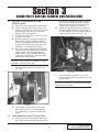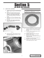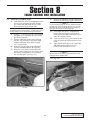
1
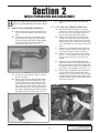
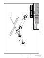
Kit # 1201219
Owner’s Installation Guide for the
Paxton Automotive
Novi 2000 Supercharger
for the
2002 Dodge 5.9L Ram 1500
Paxton Automotive . 1300 Beacon Place . Oxnard CA 93033
888 9-PAXTON . FAX (805) 604-1337
DP/N: 4809621 - Ram 1500 v1.0
09/18/03
FOREWORD
T
his manual provides information on the installation, maintenance and service of the
Paxton supercharger kit expressly designed for the 2002 5.9L Dodge Ram 1500.
Contact Paxton Automotive Corporation for any additional information regarding
this kit and any of these modifications at (805) 604-1336 7:00am-3:30pm PST.
An understanding of the information contained herein will help novices, as well as experienced technicians, to correctly install and receive the greatest possible benefit from their
Paxton supercharger. When reference is made in this manual to a brand name, number, specific tool or technique, an equivalent product may be used in place of the item mentioned.
All information, illustrations and specifications contained herein are based on the latest
product information available at the time of this publication. All rights reserved to make
changes at any time without notice.
This is a typical underhood shot after installaton. Your engine compartment may
appear different.
© 2004 PAXTON AUTOMOTIVE
All rights reserved. No part of this publication may be reproduced, transmitted, transcribed, or translated into
another language in any form, by any means without written permission of Paxton Automotive.
P/N: 4809621
©2003 Paxton Automotive
All Rights Reserved, Intl. Copr. Secured
18SEP03 v1.0 Dodge Ram 1500(4809621v1.0)
ii
TABLE OF CONTENTS
FOREWORD . . . . . . . . . . . . . . . . . . . . . . . . . . . . . . . . . . . . . . . . . . . . . . . . . . . . . . . . .ii
TABLE OF CONTENTS . . . . . . . . . . . . . . . . . . . . . . . . . . . . . . . . . . . . . . . . . . . . . . . .iii
RECOMMENDED TOOLS FOR INSTALLATION: . . . . . . . . . . . . . . . . . . . . . . . . . . .iv
1.1
INTRODUCTION . . . . . . . . . . . . . . . . . . . . . . . . . . . . . . . . . . . . . . . . . . . . . . .1-1
2.1
INITIAL PREPARATION AND DISASSEMBLY . . . . . . . . . . . . . . . . . . . . . .2-1
3.1
RELOCATION AND MODIFICATIONS . . . . . . . . . . . . . . . . . . . . . . . . . . . . .3-1
4.1
SUPERCHARGER INSTALLATION AND ASSEMBLY . . . . . . . . . . . . . . . . .4-1
5.1
AIR INTAKE AND DISCHARGE . . . . . . . . . . . . . . . . . . . . . . . . . . . . . . . . . .5.1
6.1
FINAL CHECK OUT AND START UP . . . . . . . . . . . . . . . . . . . . . . . . . . . . . .6-1
APPENDIX
. . . . . . . . . . . . . . . . . . . . . . . . . . . . . . . . . . . . . . . . . . . . . . . . . .A-1
Appendix
1201219
Kit, 2002 5.9 Dodge Ram Kit . . . . . . . . . . . . . . . . . . . .A-2
Appendix 1
1016418
Asy, S/C 2002 Dodge N2K CRV . . . . . . . . . . . . . . . . . .A-3
Appendix 2
1020220
Asy, Washer Botl Ram . . . . . . . . . . . . . . . . . . . . . . . . . .A-4
Appendix 3
1016624
Asy, S/C Mtg Brkt . . . . . . . . . . . . . . . . . . . . . . . . . . . . .A-5
Appendix 4
1015938
Asy, Air Intake 02 5.9 Ram . . . . . . . . . . . . . . . . . . . . . .A-6
Appendix 5
1020119
Asy, Air Discharge 02, 5.9 Ram . . . . . . . . . . . . . . . . . .A-7
Appendix 6
1019345
Asy, S/C Oil Supply . . . . . . . . . . . . . . . . . . . . . . . . . . .A-8
Appendix 7
1016070
Asy, S/C Oil Drain . . . . . . . . . . . . . . . . . . . . . . . . . . . .A-9
Appendix 8
1017417
Asy, Belt Tensioner . . . . . . . . . . . . . . . . . . . . . . . . . . .A-10
Appendix 9
1019717
Asy, Crank Pulley . . . . . . . . . . . . . . . . . . . . . . . . . . . . .A-11
Appendix 10
1020215
Asy, Coil Reloc. . . . . . . . . . . . . . . . . . . . . . . . . . . . . . .A-12
Appendix 11
1015510
Asy, Compressor Bypass . . . . . . . . . . . . . . . . . . . . . . .A-13
Appendix 12
1017737
Asy, Fuel Sys 02, 5.9 Ram . . . . . . . . . . . . . . . . . . . . . .A-14
Appendix 13
1017733
Asy, Fuel Enrichment 02, 5.9 Ram . . . . . . . . . . . . . . . .A-15
Appendix 14
5A001-080 Wiring Diagram . . . . . . . . . . . . . . . . . . . . . . . . . . . . . .A-16
iii
P/N: 4809621
©2003 Paxton Automotive
All Rights Reserved, Intl. Copr. Secured
18SEP03 v1.0 Dodge Ram 1500(4809621v1.0)
RECOMMENDED TOOLS
FOR INSTALLATION:
1. Metric and Standard sockets
sets
2. Metric and Standard combination
wrenches
3. Phillips and common screw drivers
4. 12" crescent wrench or 36mm
open end wrenches
5. Pliers
6. Wire cutters and wire crimping Tool
7. Hose cutters
8. 1/8" and 37/64" drill bit and hand
drill
9. 12 mm allen wrench
10. Small heat source
11. 3/8 Tap NPT
12. Ruler
13. Air compressor
14. Air hammer
P/N: 4809621
©2003 Paxton Automotive
All Rights Reserved, Intl. Copr. Secured
18SEP03 v1.0 Dodge Ram 1500(4809621v1.0)
iv
Section 1
INTRODUCTION
1.1
INTRODUCTION
C
ongratulations! You have purchased the
finest street Supercharger available for
the 2002 5.9L Dodge Ram 1500. The
centerpiece of this kit is the highly efficient
and reliable Paxton Automotive Corp. NOVI2000 supercharger. A mechanically driven (by
belt) centrifugal blower (supercharger).
This kit comes with all of the parts you’ll need
for a successful installation. The operations
required have been grouped in order of
sequence. Photos and drawings accompany the
text, allowing quick orientation and parts identification.
Installation requires a selection of tools which
is listed on page iv.
We also suggest that you obtain a Dodge shop
manual and become familiar with the details of
your cars systems. Manuals may be obtained
from your local Dodge dealer or you can order
one from Helm publications at (800)
782-4356.
For best results follow the instructions closely
and in sequence. The average installation time
for this kit is 8-10 hours. Your actual installation time will depend on skill level and working conditions. The estimate does not include
time for initial vehicle inspection, cleaning,
fine tuning or troubleshooting. Before even
picking up a wrench, read this entire manual.
We are available for technical assistance at
(805) 604-1336, 8am-4:30pm pacific time.
After reading the manual, verify that all major
assembly groups are present in the main kit
box. You should have ample space to layout
the components. As you remove a box or bag
from the main kit, note the identification label
and compare it with the parts list. Please check
the box for small parts.
Paxton makes every effort to insure that all
parts are included in the box. However, if you
discover any missing or mislabeled parts,
please contact Paxton by phone for service.
***WARNING***
DO NOT attempt installation if any part(s) are missing
from this kit. Failure to contact Paxton prior to beginning
installation will result in a charge for any missing parts.
Before starting the installation, we suggest
your engine compartment be clean. You can
clean the engine and compartment with a pressure washer (such as those used at self serve
car washes) and a safe-for-aluminum
cleaner/degreaser. Cover the distributor with a
plastic bag to prevent water from entering.
***CAUTION***
We do not recommend proceeding with the kit installation unless your vehicle is within normal operating
parameters.
You are undoubtedly enthusiastic about getting
started on your project, but take just a little
more time to insure that your safety is not
jeopardized. A moment’s lack of attention can
result in an accident, as can failure to observe
certain simple safety precautions. The possibility of an accident will always exist, and the
following points should not be considered a
comprehensive list of all dangers. Rather, they
are intended to make you aware of the risk and
to encourage a safety conscious approach to all
work you do on your vehicle.
We look forward to hearing from you, particularly if you
have any comments or suggestions regarding this manual at (805) 604-1336
Paxton Automotive Corporation
1300 Beacon Place
Oxnard, CA 93033
E-mail Address [email protected].
*** NOTE ***
Throughout these procedures the word “discard” is used
periodically in relationship to items that will no longer be
utilized in conjunction with the supercharger installation.
It is recommended that these items be saved for future
use should it become necessary.
1-1
P/N: 4809621
©2003 Paxton Automotive
All Rights Reserved, Intl. Copr. Secured
18SEP03 v1.0 Dodge Ram 1500(4809621v1.0)
•
Never rely solely on a jack when working under a vehicle. Always
use an approved set of jackstands to support the vehicle and place
them under the recommended lift points.
•
When jacking a vehicle, make sure it is on a level surface, preferably concrete or asphalt. The transmission should be in “PARK” or
“FIRST”, the parking brake engaged and the wheels blocked.
•
Never start the car without first verifying that the transmission is in
neutral and the parking brake is set.
•
Never remove the radiator cap while the engine is hot.
•
Always wear eye protection when using power tools such as drills,
saws, grinders, etc., or when working under a vehicle.
•
Never smoke, use an open flame, or have spark-producing items
around gasoline or flammable solvents. Always have a fire extinguisher rated for chemical and electrical fires handy when working
on motor vehicles.
•
Run engines only in well ventilated areas. Carbon monoxide, gasoline, and solvent vapors are colorless and sometimes odorless.
These can asphyxiate or explode without warning.
•
Always disconnect at least the negative (-) or ground terminal of the
battery when doing any electrical, fuel system, or underdash work.
Paxton Automotive makes every effort to insure that all parts are
included in the box, but mistakes do occur. If you discover that you are
missing any part, or that a part is damaged in transit, please call
Paxton Automotive for service. DO NOT attempt installation if any
part(s) are missing from this kit. Failure to contact Paxton prior to
beginning installation will result in a charge for any missing parts.
We look forward to hearing from you, particularly if you have any comments
or suggestions regarding this manual.
P/N: 4809621
©2003 Paxton Automotive
All Rights Reserved, Intl. Copr. Secured
18SEP03 v1.0 Dodge Ram 1500(4809621v1.0)
1-2
Section 2
INITIAL PREPARATION AND DISASSEMBLY
B
egin the initial preparation and disassembly
process by disconnecting the battery cables.
2.1
E.
2.2
AIR INTAKE ASSEMBLY REMOVAL
Reinstall the inner fender liner bolts and
clips.
FAN AND FAN SHROUD REMOVAL
A. Start by draining coolant in to a suitable
container. Locate the coolant petcock on the
drivers side of the truck attach a piece of
hose to the petcock and drain coolant.
B. Remove the 10mm bolt that attaches the
coolant over flow bottle to the fan shroud
and disconnect the overflow hose from the
radiator and set the coolant bottle to the side
to be reinstalled in a later stage of the installation.
C. Remove the windshield washer bottle hose
from the washer pump along with the connector. Drain washer fluid if necessary.
D. Remove the fan clutch nut using A factory
tool or a 1 1/16 wrench. Once you have the
nut loose allow the fan to rest in the fan
shroud.
E. Remove the two 13mm headed bolt that
attach the shroud to the radiator and remove
the fan, fan shroud and window washer bottle together. And set aside to be installed in a
later stage of the installation. (See Fig. 2-c.)
F. Remove the windshield washer bottle from
the fan shroud. From the backside of the
shroud you will find a flat tab. You will have
to bend this tab to remove the washer bottle
from the shroud. Set the washer bottle aside
it will not be reused.
A. Remove the spring clips that retain the top
cover of the air assembly. And remove the
filter.
B. Using an 8mm socket or flat blade screw
driver loosen the clamps from the Rubber
flex hose between the air box and the throttle body. Remove the cover and the flex
hose and set aside. (See Fig. 2-a.)
Fig. 2-a
C. Lift out the lower portion of the air cleaner
box and set aside.
D. Remove the fasteners and clips that retain
the passenger side inner fender liner. This
will aid in access to the two fasteners that
secure the air filter housing bracket to the
inner frame rail. Next remove the two bolts
that are located on the side of the frame in
the engine compartment and lift the bracket
assembly out and set a side. (See Fig 2-b.)
Fig. 2-c
Fig. 2-b
2-1
P/N: 4809621
©2003 Paxton Automotive
All Rights Reserved, Intl. Copr. Secured
18SEP03 v1.0 Dodge Ram 1500(4809621v1.0)
2.3
ACCESSORY BELT, AND BELT
TENSIONER REMOVAL
A. Remove the Accessory belt by detensioning
the Factory tensioner rotate the tensioner in
a clock wise direction using a 15 mm
wrench (See Fig. 2-d.)
Fig. 2-f
D. Remove the three bolts and nuts that retain
the tensioner bracket and set aside to be
reused in a later step of the installation. (See
Fig. 2-g.)
Fig. 2-d
B.
Remove the bolt attaching the dipstick to the
alternator bracket and set the bolt aside to be
reinstalled in a later step. (See Fig. 2-e.)
Fig. 2-g
Fig. 2-e
C. Remove the nut that attaches the factory tensioner and set the tensioner aside to be reinstalled in a later step. (See Fig. 2-f.)
P/N: 4809621
©2003 Paxton Automotive
All Rights Reserved, Intl. Copr. Secured
18SEP03 v1.0 Dodge Ram 1500(4809621v1.0)
2-2
Section 3
CRANK PULLEY AND COIL REMOVAL AND INSTALLATION
3.1
CRANK PULLEY REMOVAL AND
INSTALLATION
A. Loosen the large crank pulley-retaining bolt.
B. Using a three jaw puller slowly remove the
pulley you will have to use the retaining bolt
to back up the puller so there will not be
damage to the crank threads.
C. Once you have the pulley removed set aside
it will not be reused.
D. With the supplied Crank pulley reinstall the
crank pulley. Using the factory-retaining
bolt or a crank pulley installation tool, slowly pull the new pulley in to place take time
with this as to not damage the threads.
E. Once the supplied pulley has been installed
remove the factory-retaining bolt. Install the
supplied dowel pins and supplied supercharger pulley spacer. Reinstall the factory
crank pulley retaining bolt using lock tight
and torque to factory specs.
B.
coil from the existing coil bracket. Remove
the factory coil bracket from the cylinder
head and set aside the coil bracket will be
replaced with a supplied coil bracket.
Attach the supplied coil bracket to the coil
with the supplied fasteners and install the
coil and bracket in its new location using the
supplied-retaining bolt. (See Fig. 3-b.)
***NOTE***
This spacer fits tight. Take care in installing it so as not
to damage it or the new crank pulley.
F.
Install the supplied supercharge pulley using
the supplied fasteners and lock tight. (See
Fig. 3-a.)
Fig. 3-b
C. You may need to extend the wires on the
factory coil plug using the supplied wire and
but connectors.
***NOTE***
This may not be necessary on all vehicles check length
first and modify if necessary)
Fig. 3-a
G. Check factory crank pulley belt for alignment with accessories. To assure that the
new crank pulley is properly installed and
seated.
3.2
COIL REMOVAL AND INSTALLATION.
A. Remove the 10mm nuts and bolt that retain
the coil disconnect the plug. And remove the
3-1
P/N: 4809621
©2003 Paxton Automotive
All Rights Reserved, Intl. Copr. Secured
18SEP03 v1.0 Dodge Ram 1500(4809621v1.0)
This Page Left Intentionally Blank.
P/N: 4809621
©2003 Paxton Automotive
All Rights Reserved, Intl. Copr. Secured
18SEP03 v1.0 Dodge Ram 1500(4809621v1.0)
3-2
Section 4
SUPERCHARGER BRACKET ASSEMBLY
4.1
SUPERCHARGER MOUNTING
BRACKET
A. Remove the pulley from the stock accessory
belt tensioner and the tensioner from the
stock bracket for re-installation.
B. This is how the bracket should look prior to
installation. (See Fig. 4-a.) Note the accessory belt tensioner bracket. This spacer will
have to be removed before you install the
bracket. The dipstick goes between the tensioner and spacer.
***NOTE***
The idler pulley and pulley stand-off have been removed.
They will be installed once the supercharger bracket has
been installed.
Fig. 4-b
D. Re-install the countersunk bolts.
E. This is how the spacer should look installed.
Short portion toward the engine block. (See
Fig. 4-c.)
REMOVE THIS SPACER BEFORE INSTALLING THE S/C BRACKET
Fig. 4-c
Fig. 4-a
C. Mount the bracket in the holes at the stock
accessory belt tensioner location. Remove
the two countersunk allen head bolts and
lower this arm to gain access to the dip-stick
bolt. (See Fig. 4-b.)
***NOTE***
When installing the spacer, you may have to bend the
dipstick. Do not bend it excessively as it will become
harder to get in and out.
4-1
P/N: 4809621
©2003 Paxton Automotive
All Rights Reserved, Intl. Copr. Secured
18SEP03 v1.0 Dodge Ram 1500(4809621v1.0)
4.2
ACCESSORY BELT TENSIONER
4.3
A. Install the tensioner using the factory nut
and washer. (See Fig. 4-d.)
IDLER PULLEY STAND-OFF
A. Install the idler pulley stand-off. (See Fig.
4-g.)
B. Install the idler pulley on the idler pulley
stand-off and tighten to approximately
35 ft/lbs.
Fig. 4-d
B. Reinstall the factory tensioner pulley and
Fig. 4-g
factory accessory belt. (See Figs. 4-e, 4-f.)
C. Install the oil drain hose to the supercharger
using the hose and hose clamp provided.
(See Fig. 4-h.)
Fig. 4-e
Fig. 4-h
C. Attach the supercharger to the mounting
bracket using the six 3/8-16 x 1-1/4" bolts
and washers provided.
Fig. 4-f
P/N: 4809621
©2003 Paxton Automotive
All Rights Reserved, Intl. Copr. Secured
18SEP03 v1.0 Dodge Ram 1500(4809621v1.0)
4-2
4.4
OIL DRAIN
A. On the passenger side of the truck, locate
the engine oil filter just below the oil filter
on the oil pan. (See Fig. 4-i.) Measure down
3/4" and make a mark. Make another mark
between the two oil pan bolts. Using a 3/16"
drill bit, drill a hole with a small piece of
wire. A welding rod works well. Confirm
there is nothing in the way of the provided
punch. You may have to rotate the engine to
gain clearance for the punch.
Fig. 4-j
C. Install the straight fitting for the oil feed
using sealant on the threads. Re-install the
sending unit.
D. Attach the 40" braided hose to the straight
fitting on the brass TEE and route the hose
toward the supercharger.
E. Attach the 90° fitting to the supercharger oil
jet using oil only on the non-flared end of
the fitting.
Fig. 4-i
With the punch provided, start to enlarge the
hole. You will need to use an air-hammer for
this. If you try to use a standard hammer it
will destroy the pan. Use anti-sieze on the
punch. By doing this, the punch will go in
easier. Be careful to only go as deep as the
shoulder. The final punched hole should
measure 9/16". Test fit the tap as you go so
that you don’t make the hole too large.
C. Use a 3/8-16 NPT tap (not provided) to cut
the threads, but don’t go all the way in.
Once you have the threads, remove the tap
and apply sealant to the threads of the supplied fitting..
D. Attach the hose to the fitting and secure it
with the supplied hose clamp. Route the
hose up to the supercharger and attach,
using the supplied hose clamps.
B.
4.6
BELT TENSIONER
A. Install the supercharger belt tensioner on the
supercharger. The tensioner mounting plate
is secured to the front of the supercharger
with the supplied countersunk fasteners, followed by the tensioner which should be oriented as shown in Appendix 5. (See Fig.
4-k.)
***NOTE***
Secure the hose so there are no dips of kinks as this
may affect supercharger life.
4.5
OIL FEED
A. Remove the oil sending unit. This is located
at the rear of the engine next to the distributor.
B. Once you have removed the sending unit,
install the supplied brass TEE. (See Fig.
4-j.)
***NOTE***
Remember to use sealant on the threads to reduce the
chance of leakage.
Fig. 4-k
4-3
P/N: 4809621
©2003 Paxton Automotive
All Rights Reserved, Intl. Copr. Secured
18SEP03 v1.0 Dodge Ram 1500(4809621v1.0)
4.7
SUPERCHARGER BELT
A. Route the supercharger belt and accessory
drive belt as shown. (See Figs. 4-k, 4-l.)
ALT
IDLER
ACCESSORY
TENSIONER
AC
PUMP
WATER
PUMP
PS
PUMP
CRANK
PULLEY
Fig. 4-k / Factory accessory belt routing diagram
Fig. 4-l / Supercharger belt routing
P/N: 4809621
©2003 Paxton Automotive
All Rights Reserved, Intl. Copr. Secured
18SEP03 v1.0 Dodge Ram 1500(4809621v1.0)
4-4
Section 5
AIR INTAKE AND DISCHARGE
5.1
AIR INTAKE ASSEMBLY
A. Install the 4" sleeve to the supercharger inlet
with the supplied clamps. Leave the clamps
loose.
B. Install the 180° plastic intake duct to the
sleeve you installed onto the supercharger.
With the 1" x 90° plastic barbed fitting
installed, attach the factory crank case vent
hose to the fitting with the provided hose
clamp.
C. Attach the 3-1/2" piece of flex hose to the
plastic duct and secure with the hose clamps
provided.
D. Insert the venturi into the end of the flex
hose that will be attached to the air filter
housing. (See Fig. 5-a.)
***NOTE***
On some vehicles you may have to trim the retaining
ring. (See Fig. 5-c) to achieve best fit.
Fig. 5-c
Install the round air filter retaining-ring onto
the filter. Install the air filter hose clamp to
the filter.
G. Check the filter and retaining ring in the filter housing for proper fit.
F.
Fig. 5-a
E.
H. Install the coupler into the air filter and
tighten the hose clamp.
I. Install the filter assembly into the filter
housing and secure with the three screw and
washers provided.
J. Attach the 3-1/2" flex hose to the filter coupler and secure the hose clamp.
K. Adjust the 180° plastic inlet duct for best fit.
Finish tightening all hose clamps.
Attach the plastic filter housing to the side
of the frame with the supplied sheet metal
screw. (See Fig. 5-b.)
Fig. 5-b
5-1
P/N: 4809621
©2003 Paxton Automotive
All Rights Reserved, Intl. Copr. Secured
18SEP03 v1.0 Dodge Ram 1500(4809621v1.0)
5.2
AIR DISCHARGE ASSEMBLY
5.3
A. Remove the four factory inlet duct bolts and
factory inlet duct adapter and set aside. It
will not be re-used.
B. Install the bonnet adapter with the fasteners
provided. Using lock tight on this bolt is
recommended. (See Fig. 5-d.)
BYPASS VALVE ASSEMBLY
A. Assemble the bypass valve as shown in
Fig. 5-f.
S/C DISCHARGE DUCT
AIR INTAKE DUCT
Fig. 5-f
Install the bypass valve with the
vacuum/boost port facing downwards and
tighten the clamps
C. Install the 5/32" vacuum hose to the port
and route to manifold vacuum.
B.
Fig. 5-d
C. Assemble the bonnet with the injectors.
Using a small amount of engine oil or lithium grease when assembling the injectors to
the bonnet will aid in the installation of the
injectors and prevent damage to the injector
O-rings. Install the bonnet to the throttle
body using the hardware provided.
D. Install the 3" sleeve to the outlet of the
supercharger with the hose clamps provided.
Do no tighten the hose clamps at this time.
E. Install the 3" sleeve with the clamps to the
end of the discharge tube that will attach to
the bonnet. Adjust the sleeves and tighten all
clamps. (See Fig. 5-e.)
Fig. 5-e
P/N: 4809621
©2003 Paxton Automotive
All Rights Reserved, Intl. Copr. Secured
18SEP03 v1.0 Dodge Ram 1500(4809621v1.0)
5-2
Section 6
FAN AND WINDSHIELD WASHER BOTTLE INSTALLATION
6.1
FAN AND FAN SHROUD INSTALLATION
D. Cut the pump and fluid level sensor plugs
leaving an adequate amount of wire away
from the plug end. Lengthen the wires.
Using the butt connectors and wire provided, lengthen the wires and attach the plugs
to the pump and level sensor in their new
location.
A. Start by installing the fan space to the water
pump and tighten to factory specs using
either a factory tool or a 1-1/16" wrench.
B. With the fan and fan shroud as an assembly,
lower the unit into place, attach the fan to
the fan spacer and using the factory fasteners removed from the fan shroud in a earlier
step, attach the fan shroud to the radiator.
Take care not to over tighten the bolts that
attach the fan shroud to the radiator. Tighten
the fan to factory specs.
6-2
WINDOW WASHER BOTTLE INSTALLATION
A. From under the vehicle, locate the radiator
support using the washer bottle bracket as a
template.
***NOTE***
You may have to bend the bracket slightly for the best fit.
Mark the two holes that will retain the washer bottle
bracket to the core support. Drill the holes using a 3/16"
drill bit.
Install the plastic washer bottle into the
bracket once the bottle has been installed.
Remove the windshield washer pump and
fluid level sensor from the factory washer
bottle and install it into the supplied washer
bottle with the factory grommets. Use a
small amount of silicone sealant on the factory grommets to prevent leakage.
C. Install the washer bottle assembly to the
holes your previously drilled in the core.
Support with the supplied sheet metal
screws and attach the washer pump hose to
the outlet using the supplied hose and conntectors. (See Fig. 6-a.)
B.
Fig. 6-a
6-1
P/N: 4809621
©2003 Paxton Automotive
All Rights Reserved, Intl. Copr. Secured
18SEP03 v1.0 Dodge Ram 1500(4809621v1.0)
This Page Left Intentionally Blank.
P/N: 4809621
©2003 Paxton Automotive
All Rights Reserved, Intl. Copr. Secured
18SEP03 v1.0 Dodge Ram 1500(4809621v1.0)
6-2
Section 7
AUXILIARY FUEL PUMP INSTALLATION
7.1
FUEL PUMP ASSEMBLY
A. Assemble the fuel pump assembly per
Appendix 1017733.
B. Install the assembled fuel pump assembly to
the transmission cross member with the supplied fasteners. (See Fig. 7-a.) The fuel
pump inlet should face the front of the vehicle.
Fig. 7-b
Attach the wire coming from the #30 terminal on the relay to the power distribution
box on the driver’s side of the vehicle using
a 3/8" ring terminal.
C. Attach the #86 terminal to the #58 factory
fuel pump relay in the power distribution
box. (See Fig. 7-c.) Attach the #86 terminal
from the supplied relay to the #87 terminal
of the factory fuel pump relay. This will be
the trigger wire that will turn the additional
fuel pump relay on.
B.
Fig. 7-a
C. Using a spring lock tool, disconnect the fuel
line located just in front of the transmission
cross member.
D. Attach the fuel pump inlet hose to the steel
fuel line coming from the fuel tank using the
90° fitting provided in the assembly.
E. Attach the fuel line that is coming from the
fuel pressure regulator to the flex line that
you disconneced from the steel hard line.
F. Take care in routing the fuel lines. Keep
them away from sharp, hot or moving parts.
G. When finished installing the fuel pump
relay, cycle the ignition several times and
check for fuel leaks.
7.2
FUEL PUMP RELAY
FUEL PUMP RELAY INSTALLATION
A. Find a suitable location on the driver’s side
of the vehicle. (See Fig. 7-b.) Locate the
fuel pump relay as close to the battery and
fuse box as possible.The location of the
relay shown is just for reference as some
vehicles may be different. Generally you
want the relay to be as close to the battery
as possible.
Fig. 7-c
D. Attach the #87 terminal wire of the additional fuel pump relay to the positive terminal of
the fuel pump. Carefully route the wire
down the firewall to the fuel pump. Be sure
to keep the wires away from hot, sharp or
moving parts.
7-1
P/N: 4809621
©2003 Paxton Automotive
All Rights Reserved, Intl. Copr. Secured
18SEP03 v1.0 Dodge Ram 1500(4809621v1.0)
E.
Attach the #85 terminal wire to a suitable
ground location.
***NOTE***
The #87A terminal will not be used.
Attach a suitable length of wire with ring
type terminals to the negative terminal on
the additional fuel pump and attach this wire
to the fuel pump assembly mounting bolt.
G. Cycle the ignition several times to confirm
the pump is running and check all fittings
for leaks.
F.
P/N: 4809621
©2003 Paxton Automotive
All Rights Reserved, Intl. Copr. Secured
18SEP03 v1.0 Dodge Ram 1500(4809621v1.0)
7-2
Section 8
ENGINE CONTROL UNIT INSTALLATION
8.1
ENGINE CONTROL UNIT
F.
A. From inside the driver’s compartment on the
driver’s side and under the dash, find the
two 15mm nuts that retain the cover that
blocks the hole for the clutch cable.
Refer to the Appendix #5A001-080 for pin
locations on the factory engine control unit.
***NOTE***
If you are installing this kit on a non California vehicle,
you may only have one oxygen sensor. If so, you will
eliminate one set of oxygen sensor wires. Cover the
wires with heat-shrink or electricians tape.
***NOTE***
On standard transmission vehicles, you will have to find
another location to run the wires through the firewall.
G. From inside the driver’s compartment,
remove the two torques screws that are
located under the dash securing the cover
under the steering column.
H. At the top of the cover, pull outward on the
cover to release the clips and set the cover
aside.
I. Apply double-stick tape to the control box
and attach the box to the cover just
removed, and reinstall the cover.
Using a 1-3/16" hole saw, cut a hole through
the plastic cover. Reinstall the cover using
the factory fasteners.
C. Pass the additional injector plugs through
the hole you just made in the cover along
with the additional wires and the length
5/32" vacuum hose.
D. Route the injector plugs to the additional
injector and attach them to the injectors.
E. Route the wires across the firewall to the
factory engine control unit. It is best to open
the factory wiring harness cover and pass
the wire through it. (See Fig. 8-a.)
B.
*** NOTE ***
Be sure there are not kinks in the vacuum/boost line
coming from the supplied ECU.
(See Fig. 8-b.)
Fig. 8-a
Fig. 8-b
8-1
P/N: 4809621
©2003 Paxton Automotive
All Rights Reserved, Intl. Copr. Secured
18SEP03 v1.0 Dodge Ram 1500(4809621v1.0)
Fig. 8-b / Congratulatlions - here is your finished supercharged engine.
P/N: 4809621
©2003 Paxton Automotive
All Rights Reserved, Intl. Copr. Secured
18SEP03 v1.0 Dodge Ram 1500(4809621v1.0)
8-2
Section 9
FINAL CHECK OUT AND START UP
9.1
INSPECT THE FOLLOWING:
A. Wires, harness and electrical connections.
Are all items properly dressed, connected
and secured?
B. Hoses, lines and fittings. Are all items properly dressed, connected and secured?
C. Check all fasteners, brackets and clamps.
Are they all properly installed and tightened?
D. Check fluid levels. Is the radiator coolant
and the engine oil at their proper levels? Are
there any fluid leaks?
E. Check all belts. Is the serpentine drive belt
(or accessory drive and supercharger drive
belts, depending on the requirement of your
vehicle) properly installed, aligned and tensioned?
9-2
PERFORM THE FOLLOWING:
A. Cycle the ignition key from the “OFF” position to the “ON” position three times at fifteen second intervals. Afterwards, check the
entire fuel system for any leaks.
***IMPORTANT***
Start the vehicle. Verify that the oil pressure is within the
normal operating rance. Listen closely. The engine
should idle and sound the same as it did before you
installation. Shut off the engine, disconnect the oil feed
line from the blower. Remove the oil jet from the blower.
Blow through the oil jet to ensure there is no blockage or
foreign matter plugging it. Re-install the oil jet and oil
feed line and proceed.
B.
9-3
Allow the engine to come up to normal
operating temperature. Bleed the cooling
system and top off as necessary.
CHECK FOR THE FOLLOWING:
A. Fuel leaks
B. Fluid leaks
C. Belt slippage
D. Throttle response
***CAUTION***
See the supercharger service manual included in your kit
for information on supercharger servicing and maintenance, belt tightening, troubleshooting, special tuning
and warranty information.
Now that the work is done, it’s time to enjoy
your labor of love. Take the vehicle out on lthe
read and let it flex it’s muscles, but remember,
the response and performance will be different
from that to which you have been accustomed.
Have fun.
9-1
P/N: 4809621
©2003 Paxton Automotive
All Rights Reserved, Intl. Copr. Secured
18SEP03 v1.0 Dodge Ram 1500(4809621v1.0)
This Page Left Intentionally Blank.
P/N: 4809621
©2003 Paxton Automotive
All Rights Reserved, Intl. Copr. Secured
18SEP03 v1.0 Dodge Ram 1500(4809621v1.0)
9-2
APPENDIX
A-1
P/N: 4809621
©2003 Paxton Automotive
All Rights Reserved, Intl. Copr. Secured
18SEP03 v1.0 Dodge Ram 1500(4809621v1.0)
P/N: 4809621
©2003 Paxton Automotive
All Rights Reserved, Intl. Copr. Secured
18SEP03 v1.0 Dodge Ram 1500(4809621v1.0)
A-2
1201216
1016418
1020220
1016624
1015938
1020117
1019345
1016070
1017417
1019717
1020215
1015510
1017735
5A001-080
1
1
1
1
1
1
1
1
1
1
1
1
1
1
1
2
3
4
5
6
7
8
9
10
11
12
13
14
DESCRIPTION
1201216
FINISH
APPR.
WEIGHT
21.4 LBS
Kit, 2000/2001 4.7L Dodge Durango
NONE
UNLESS OTHERWISE SPECIFIED
CAD GENERATED DRAWING,
DIMENSIONS ARE IN INCHES
DO NOT MANUALLY UPDATE
TOLERANCES ARE: .XX± .01
DECIMALS:
.XXX±.005
DATE
APPROVALS
±1/2•
FRACTIONS:
DRAWN
G. COMPTON
1/16/01
ANGLES:
±1/16
ENGINEERING
MATERIAL
R&D
SEE PARTS LIST
PAXTON ENGINE CONTROL UNIT, '02 RAM
ASY, FUEL ENRICHMENT SYS., '02 RAM
ASY, COMPRESSOR BYPASS, '02 RAM
ASY, COIL RELOC., '02 RAM
ASY, CRANK PULLEY, '02 RAM
ASY, BELT TENSIONER, '02 RAM
ASY, OIL DRAIN, '02 RAM
ASY, S/C OIL SUPPLY, '02 RAM
ASY, AIR DISCHARGE, '02 RAM
ASY, AIR INTAKE, '02 RAM
ASY, S/C MTG BRKT, '02 RAM
ASY, WASHER BOTL, '02 RAM
S/C ASY, 2002 DODGE NK2 CRV
KIT, 2002 5.9 DODGE RAM KIT
Appendix 1
PART NO.
QTY.
ITEM NO.
SCALE:
SIZE
B
1:1
1201216
DO NOT SCALE DRAWING
DWG. NO.
REV.
NC
SHEET 1 OF 1
KIT, 2000/2001 4.7L DODGE DURANGO
2002 DODGE RAM
1300 BEACON PLACE OXNARD, CA 93033
TEL: (805) 604-1336 FAX: (805) 604-1337
A-3
P/N: 4809621
©2003 Paxton Automotive
All Rights Reserved, Intl. Copr. Secured
18SEP03 v1.0 Dodge Ram 1500(4809621v1.0)
12
8
9
6
4
18
19
3
1
32 31 30 26 2
29 28 27 2
23
2
3
8
3. TORQUE TO 36 FT-LBS.
Appendix 2
22
5 4
15 2
7
31 2 4
20
32 3
2
2
FINISH
APPR.
WEIGHT
21.8 LBS
G. COMPTON
4/11/01
Asy, S/C Novi 2000 Pwr Rotation, Rear Discharge
NONE
2002 DODGE RAM 5.9L
1300 BEACON PLACE OXNARD, CA 93033
TEL: (805) 604-1336 FAX: (805) 604-1337
PART NO.
DESCRIPTION
2H238-000
GEARCASE ASY, N2K, CW, SAT
7P375-625
FTG, NIPPLE, 3/8NPT X 5/8 HOSE BARB
7P375-016
FTG, PLUG, 3/8NPT WITH MAGNET
7J375-024
WASHER, COPPER CRUSH
7PP375-090 OIL JET, LONG
7P375-104
SCREW, SCHD, 3/8-16UNC-2A X 1.00 LG.
008704
CAP, SHIPPING, T2
7U100-075
KEY, 1/8 SQ. X 1.25 LG.
2H017-125
SPACER, PULLEY, .125 THK.
2H038-325
PULLEY, S/C 8 GRV, 3.25
2H040-021
RET, CUP BLWR, PULLEY
2H040-011
PULLEY RETAINER S/C
008718
CAP, TAMPER PROOF
7B375-110
SCREW, HXHD, 3/8-24UNF-2A X 1.00 LG.
2H018-051
VOLUTE, MACH, CURV, N2K
008706
CAP, SHIPPING, 3"
008719
CAP, SHIPPING, 4"
2H100-035
NAMEPLATE, NOVI 2000
7U100-021
DRIVE SCREW, #4 X .187, GR5
2H017-021
WASHER, ANTI-ROTATION
2H100-045
CLAMP, VOLUTE
7A250-050
1/4-20 X .50 SHCS
008720
CAP, SHIPPING, T5
2H060-030
MATING RING, .090 THK.
2H100-003
SHIM, IMP, .003 THK.
2H100-005
SHIM, IMP, .005 THK.
2H100-010
SHIM, IMP, .010 THK.
2H060-031
MATING RING, .099 THK.
2H060-040
MATING RING, .103 THK.
2H060-041
MATING RING, .112 THK.
2H021-211
IMPLR, BAL, NOVI 2K, CCW
2H060-030
MATING RING, .090 THK
2H100-003
SHIM, IMP, .003 THK.
7F375-024
NUT, IMP 3/8 LH SL 6PT
16
ASY, S/C NOVI 2000 FWR ROTATION, REAR DISCHARGE,
99-01 5.2/5.9L, SATIN
SIZE
DWG. NO.
REV.
1016418
D
C
SCALE: 3:4
DO NOT SCALE DRAWING
SHEET 1 OF 1
ITEM NO. QTY.
1
1
1
2
2
3
2
4
1
5
1
6
1
7
2
8
2
9
1
10
1
11
1
12
1
13
1
14
1
15
1
16
1
17
1
18
4
19
1
20
3
21
6
22
1
23
0
24
0
25
0
26
0
27
0
28
0
29
0
30
1
31
1
24
1
25
1
32
17
UNLESS OTHERWISE SPECIFIED
CAD GENERATED DRAWING,
DIMENSIONS ARE IN INCHES
DO NOT MANUALLY UPDATE
TOLERANCES ARE: .XX± .01
DECIMALS:
.XXX±.005
DATE
APPROVALS
±1/2•
FRACTIONS:
DRAWN
A. PROCTOR
3/28/01
ANGLES:
±1/16
ENGINEERING
3/29/01
G. COMPTON
MATERIAL
R&D
SEE PARTS LIST
4/9/01
L. KECK
21
1016418
2. SHIM IMPELLER TO .031 WORKING HEIGHT WITH ITEMS 24, 25, 26, 27, 28, 29 AND 30(FLOOR STOCK) AS REQUIRED.
1. ALL PARTS TO BE SUITABLY PROTECTED AT ALL TIMES TO PREVENT DAMAGE.
NOTES: UNLESS OTHERWISE SPECIFIED
13
14
11
10
LONG HUB
S/C ROTATION
ALIGN MOUNTING HOLE
IN VOLUTE WITH EDGE
OF GEARCASE AS
SHOWN.
P/N: 4809621
©2003 Paxton Automotive
All Rights Reserved, Intl. Copr. Secured
18SEP03 v1.0 Dodge Ram 1500(4809621v1.0)
A-4
5
7
STACK LEVEL
SENSOR
5
1
TO WINDSHIELD
WASHER PUMP
Appendix 3
6
1020220
2
24"
2
2
8
9
48"
5
24"
8
4
7
36"
3
6
5 FT
1
1
2
QT
ITEM
PART NO.
7
7E014-075
7U375-052
5W018-040
5W018-090
5W018-020
5W001-012
5W001-005
7U030-046
4PCE055-011
5
TO FACTORY
HARNESS
FINISH
WEIGHT
APPR.
Asy, Washer Bottle Relocation
NONE
UNLESS OTHERWISE SPECIFIED
CAD GENERATED DRAWING,
DIMENSIONS ARE IN INCHES
DO NOT MANUALLY UPDATE
TOLERANCES ARE: .XX± .01
DECIMALS:
.XXX±.005
DATE
APPROVALS
±1/2•
FRACTIONS:
DRAWN
LK
06/28/02
ANGLES:
±1/16
ENGINEERING
MATERIAL
R&D
SEE PARTS LIST
STOCK WINDSHIELD
WASHER PUMP
TO FACTORY
SPLICE
3
4
B
SCALE: NONE
SIZE
1020220
DO NOT SCALE DRAWING
DWG. NO.
REV.
A
SHEET 1 OF 1
ASY, WASHER BOTTLE RELOCATION
2002 DODGE RAM 5.9L
1300 BEACON PLACE OXNARD, CA 93033
TEL: (805) 604-1336 FAX: (805) 604-1337
#14 x .75 SHEETMETAL SCREW
3/8 VACCUM CAP
WIRE, 18AWG WHITE x 24"LG
WIRE, 18AWG BROWN x 24" LG
WIRE, 18AWG BLACK x 48" LG
CONNECTOR, BUTT 18-22 GA
TUBING, BLACK SPLIT POLY LOOM 3/8" I.D. x 36" LG
HOSE, WASHER, 5/32" I.D. x 46" LG
WINDOW WASHER BOTTLE MODIFIED
DESCRIPTION
6
5
A-5
P/N: 4809621
©2003 Paxton Automotive
All Rights Reserved, Intl. Copr. Secured
18SEP03 v1.0 Dodge Ram 1500(4809621v1.0)
1
7 5
1
1
4 PLACES 6
TO S/C 1
Appendix 4
PLACES
9 5 5
TO S/C
7 5
1
1016624
FINISH
WEIGHT
Asy, S/C Mounting Bracket
NONE
APPR.
7.2 LBS
G. COMPTON
4/19/01
SCALE:
SIZE
ITEM NO. QTY.
1
1
1
2
1
3
1
4
9
5
4
6
3
7
1
8
5
9
1
10
1
11
1
12
1
13
2
UNLESS OTHERWISE SPECIFIED
CAD GENERATED DRAWING,
DIMENSIONS ARE IN INCHES
DO NOT MANUALLY UPDATE
TOLERANCES ARE: .XX± .01
DECIMALS:
.XXX±.005
DATE
APPROVALS
±1/2•
FRACTIONS:
DRAWN
G. COMPTON
3/29/01
ANGLES:
±1/16
ENGINEERING
3/29/01
G. COMPTON
MATERIAL
R&D
SEE PARTS LIST
4/19/01
L. KECK
8 5
NOT USED
4
1:1
D
TO
ENGINE
BLOCK
DO NOT SCALE DRAWING
1016624
ASY, S/C MTG BRKT
DWG. NO.
REV.
A
SHEET 1 OF 1
1300 BEACON PLACE OXNARD, CA 93033
TEL: (805) 604-1336 FAX: (805) 604-1337
DESCRIPTION
PLATE, FRONT S/C MTG
PLATE, SUPPORT, SHORT
PLATE, SUPPORT, LONG
SPACER, .88 x .39 x 3.114 LG
WASHER, 3/8 SAE PLTD
SCREW, 5/16-18 x 1.00 LG
SCREW, 3/8-16 x 4.50 LG
SCREW, 3/8-16 x 4.25 LG
3/8-16 x 1-1/4 HXHD
3/8-16 x 1.0 FL SHCS
COLLAR, STEP 8 GRV
ASY, IDLER PULLEY
PULLEY RETAINER S/C
TO ENGINE
BLOCK
2002 DODGE RAM 5.9L
PART NO.
4PCE010-034
4PCD010-160
4PCD010-150
4PCD017-021
7J375-044
7A312-102
7A375-451
7A375-425
7A375-124
7A375-102
4PCE017-011
1210516
2H040-011
3
TO
ENGINE
BLOCK
P/N: 4809621
©2003 Paxton Automotive
All Rights Reserved, Intl. Copr. Secured
18SEP03 v1.0 Dodge Ram 1500(4809621v1.0)
A-6
4PCE012-061
4PCE012-050
7L010-001
8H040-050
7C010-039
7R002-064
7PS400-200
7P250-124
4PFA012-010
7U035-001
7P750-102
4GV012-041
7R002-052
7U030-036
7E014-015
7J250-150
4PCE017-031
3
1
3
5
1
1
1
1.33
1
1
2
4'
2
2
1
PART NO
1
1
QTY
Appendix 5
#14 x 1.5 SHEET METAL SCREW
1/4" FENDER WASHER
RESTRICTOR, AIR
3/4 NPT x 1 x 90° HOSE FTG
MASS AIR TUBE COATED
#52 SAE TYPE SS HOSE CLAMP
1/2 OIL DRAIN HOSE
1/4 NPT TO1/2 BARD
INLET ELBOW, 180° 4 x 3.5
3.5 FLEX HOSE
10-24 x .38 PAN HD PHIL SS
#64 SAE TYPE F SS HOSE CLAMP
SLEEVE, BLACK 4.0D x 2.0
WASHER #10 SERRATED LOCK
AIR FILTER 3.5 FLG x 7" LONG
AIR BOX 02 DODGE 5.9
RING FILTER RETAINING
DESCRIPTION.
1015938
FINISH
WEIGHT
APPR.
Asy, Air Intake
NONE
?.? LBS
UNLESS OTHERWISE SPECIFIED
CAD GENERATED DRAWING,
DIMENSIONS ARE IN INCHES
DO NOT MANUALLY UPDATE
TOLERANCES ARE: .XX± .01
DECIMALS:
.XXX±.005
DATE
APPROVALS
±1/2•
FRACTIONS:
DRAWN
L. KECK
6/25/03
ANGLES:
±1/16
ENGINEERING
MATERIAL
R&D
SEE PARTS LIST
SCALE:
SIZE
A
?:?
1015938
DO NOT SCALE DRAWING
DWG. NO.
AIR INTAKE ASSY
2002 DODGE 5.9
REV.
B
SHEET 1 OF 1
1300 BEACON PLACE OXNARD, CA 93033
TEL: (805) 604-1336 FAX: (805) 604-1337
A-7
P/N: 4809621
©2003 Paxton Automotive
All Rights Reserved, Intl. Copr. Secured
18SEP03 v1.0 Dodge Ram 1500(4809621v1.0)
11 12
16
14
TO THROTTLE
1
13 11
TO S/C ASY
4
5
10
15
17
17
2
6
8
FINISH
WEIGHT
Asy, Air Discharge
NONE
APPR.
5.7 LBS
-----
-----
D
1020119
DO NOT SCALE DRAWING
DWG. NO.
ASY, AIR DISCHARGE
00/01 5.9L DODGE DURANGO/RT
REV.
NC
SHEET 1 OF 1
1300 BEACON PLACE OXNARD, CA 93033
TEL: (805) 604-1336 FAX: (805) 604-1337
DESCRIPTION
BONNET, MACHINING
RAIL, FUEL INJECTOR
STRAP, FUEL RAIL 2.10 LG
CONN, MALE 1/8NPT x 1/4 TUBE SEA 45° FLARE
ASY, FUEL ENRICHMENT LINE
SCREW, SHCS, TORX, 10-24UNC-2A x .38 LG.
INJECTOR, 36 LBS
TUBE, DISCHARGE
CLAMP, HOSE #48
WASHER, 1/4 FLAT SAE GR
SCREW, HXHD, 1/4-20UNC-2A x 1.25 LG.
SCREW, HXHD, 1/4-20UNC-2A x 1.75 LG.
ADAPTER, BONNET
PLUG, PIPE 1/8NPT HEX SOC
GASKET, 5.50 O.D. x 5.00 I.D. x .09 THK
SCALE: 1:1.5
SIZE
ITEM NO. QTY. PART NO.
1
1
8002332
2
1
4870004
3
1
8002383
4
1
4823400
5
1
1018306
6
2
8000109-1
7
8002126
2
8
1
4810175
10
4
1055970
11
2
1003110
12
1
1021280
13
1
1021250
14
1
4870024
15
2
2716900
16
1
4870001
17
2
7PS300-200
UNLESS OTHERWISE SPECIFIED
CAD GENERATED DRAWING,
DIMENSIONS ARE IN INCHES
DO NOT MANUALLY UPDATE
TOLERANCES ARE: .XX± .01
DECIMALS:
.XXX±.005
DATE
APPROVALS
±1/2•
FRACTIONS:
DRAWN
G. COMPTON
3/29/01
ANGLES:
±1/16
ENGINEERING
--------MATERIAL
R&D
SEE PARTS LIST
---------
6
10
10
1020119
TO FUEL RAIL
3
Appendix 6
7
10
F
P/N: 4809621
©2003 Paxton Automotive
All Rights Reserved, Intl. Copr. Secured
18SEP03 v1.0 Dodge Ram 1500(4809621v1.0)
A-8
TO S/C OIL JET
3
Appendix 7
1
TO STOCK OIL
SENDER UNIT
2
1
1
1
1
2
3
4
QTY.
1
ITEM NO.
PART NO.
FINISH
WEIGHT
Asy, S/C Oil Supply
NONE
APPR.
0.7 LBS
G. COMPTON
4/11/01
SCALE:
SIZE
7P125-034
7P125-004
7P125-005
7U250-090-320
UNLESS OTHERWISE SPECIFIED
CAD GENERATED DRAWING,
DIMENSIONS ARE IN INCHES
DO NOT MANUALLY UPDATE
TOLERANCES ARE: .XX± .01
DECIMALS:
.XXX±.005
DATE
APPROVALS
±1/2•
FRACTIONS:
DRAWN
G. COMPTON
3/29/01
ANGLES:
±1/16
ENGINEERING
3/29/01
G. COMPTON
MATERIAL
R&D
SEE PARTS LIST
4/9/01
L. KECK
1019345
4
TO CYLINDER HEAD
C
1:1
1019345
DO NOT SCALE DRAWING
DWG. NO.
ASY, S/C OIL SUPPLY
2002 DODGE RAM 5.9L
REV.
A
SHEET 1 OF 1
1300 BEACON PLACE OXNARD, CA 93033
TEL: (805) 604-1336 FAX: (805) 604-1337
FTG, STREET ELBOW, 1/8 NPT
FTG, STRT #4 AN MALE x 1/8 NPT MALE
FTG, ELBOW 90^ #4 AN x 1/8 NPT
DESCRIPTION
HOSE, OIL SST BRAID #4 x 32" LG
A-9
P/N: 4809621
©2003 Paxton Automotive
All Rights Reserved, Intl. Copr. Secured
18SEP03 v1.0 Dodge Ram 1500(4809621v1.0)
TO OIL PAN
3
2
Appendix 8
1
ITEM NO.
1
2
4
3
QTY.
1
2
1
1
PART NO.
7U033-000X18
7R002-010
7T640-011
7P375-625
1016070
FINISH
Asy, Oil Drain
NONE
WEIGHT
APPR.
0.5 LBS
G. COMPTON
1:1
C
1016070
DO NOT SCALE DRAWING
DWG. NO.
ASY, OIL DRAIN
2002 DODGE RAM 5.9L
REV.
A
SHEET 1 OF 1
1300 BEACON PLACE OXNARD, CA 93033
TEL: (805) 604-1336 FAX: (805) 604-1337
CLAMP, HOSE, #10
PUNCH, OIL PAN
FTG, NIPPLE, 3/8NPT x 5/8 HOSE BARB
DESCRIPTION
SCALE:
10/06/00 SIZE
UNLESS OTHERWISE SPECIFIED
CAD GENERATED DRAWING,
DIMENSIONS ARE IN INCHES
DO NOT MANUALLY UPDATE
TOLERANCES ARE: .XX± .01
DECIMALS:
.XXX±.005
DATE
APPROVALS
±1/2•
FRACTIONS:
DRAWN
A. PROCTOR
9/08/00
ANGLES:
±1/16
ENGINEERING
9/13/00
G. COMPTON
MATERIAL
R&D
SEE PARTS LIST
10/06/00
L. KECK
1
2
TO S/C ASY
P/N: 4809621
©2003 Paxton Automotive
All Rights Reserved, Intl. Copr. Secured
18SEP03 v1.0 Dodge Ram 1500(4809621v1.0)
A-10
5
4
2
3
Appendix 9
10
8
1017417
3
7
6
FINISH
APPR.
WEIGHT
Asy, Belt Tensioner (8-Grv)
NONE
5.3 LBS
G. COMPTON
4/10/01
D
SCALE: 1.25:1
SIZE
PART NO.
4PCD011-038
TEST-BOM
1017417
DO NOT SCALE DRAWING
DWG. NO.
ASY, BELT TENSIONER(8 GRV)
2002 DODGE RAM 5.9L
REV.
A
SHEET 1 OF 1
1300 BEACON PLACE OXNARD, CA 93033
TEL: (805) 604-1336 FAX: (805) 604-1337
DESCRIPTION
TENSIONER, BELT SPRING LOADED
SCREW, 3/8-16 x .75 FLHS GR8
WASHER, 3/8 SAE PLTD
SCREW, 3/8-16 x 3.50 HXHD GR8
SCREW, 8mm x 1.25 x 35mm HXHD CLASS 8.8
COLLAR, PULLEY SPRING TENSIONER
ASY, PULLEY TENSIONER 8 GRV
ASY NO. ITEM
1017415-P
1
1017416
1
ITEM NO. QTY.
PART NO.
1 4PGM011-061
2
2
7a375-077
3
1
7J375-044
4
1
7A375-350
5
7C080-035
6
1
7
1 4PGM017-011
1210515
8
1
4PCD011-032
10
1
2H013-011
11
1
UNLESS OTHERWISE SPECIFIED
CAD GENERATED DRAWING,
DIMENSIONS ARE IN INCHES
DO NOT MANUALLY UPDATE
TOLERANCES ARE: .XX± .01
DECIMALS:
.XXX±.005
DATE
APPROVALS
±1/2•
FRACTIONS:
DRAWN
A. PROCTOR
3/29/01
ANGLES:
±1/16
ENGINEERING
3/29/01
G. COMPTON
MATERIAL
R&D
SEE PARTS LIST
4/9/01
L. KECK
TENSIONER
S/C GEAR COVER
A-11
P/N: 4809621
©2003 Paxton Automotive
All Rights Reserved, Intl. Copr. Secured
18SEP03 v1.0 Dodge Ram 1500(4809621v1.0)
NOTES: UNLESS OTHERWISE
SPECIFIED
IDLER
PULLEY
S/C
PULLEY
5
TENSION
PULLEY
Appendix 10
9 2 6X
7
FINISH
WEIGHT
Asy, Crank Pulley
NONE
APPR.
13.0 LBS
G. COMPTON
4/11/01
D
PART NO.
4PCD018-011
7K312-001
4PCE017-021
2A048-635
4PCE016-011
7U187-075
7A312-100
SCALE: 1:1.5
SIZE
ITEM NO. QTY.
1
1
6
2
1
3
1
5
1
1
6
3
7
6
9
UNLESS OTHERWISE SPECIFIED
CAD GENERATED DRAWING,
DIMENSIONS ARE IN INCHES
DO NOT MANUALLY UPDATE
TOLERANCES ARE: .XX± .01
DECIMALS:
.XXX±.005
DATE
APPROVALS
±1/2•
FRACTIONS:
DRAWN
G. COMPTON
3/30/01
ANGLES:
±1/16
ENGINEERING
3/30/01
G. COMPTON
MATERIAL
R&D
SEE PARTS LIST
4/9/01
L.KECK
1019717
1
3
6
CRANK SHAFT
1019717
DO NOT SCALE DRAWING
DWG. NO.
ASY, CRANK PULLEY
2002 DODGE RAM 5.9L
REV.
A
SHEET 1 OF 1
1300 BEACON PLACE OXNARD, CA 93033
TEL: (805) 604-1336 FAX: (805) 604-1337
DESCRIPTION
PULLEY, CRANK 6 GRV
WASHER, 5/16 FLT SST
SPACER, CRANK
BELT, 8 GRV MICRO-V 1630mm x 28mm
HARMONIC BALANCER, MODIFIED
PIN, DOWEL, 3/16 x .75 LG.
5/16" - 18 x 1.00" HHCS
P/N: 4809621
©2003 Paxton Automotive
All Rights Reserved, Intl. Copr. Secured
18SEP03 v1.0 Dodge Ram 1500(4809621v1.0)
A-12
2
3
1. THESE ITEMS SHIP LOOSE.
NOTES: UNLESS OTHERWISE SPECIFIED
2X
1
Appendix 11
7J250-001
1020215
FINISH
WEIGHT
APPR.
Asy, Coil Relocation
NONE
TUBING SPLIT POLY LOOM
5W001-032
.7 FT
7
1
0.2 LBS
G. COMPTON
10/6/01
✒
SCALE:
1:1
CONN, BUTT 22-18 GA
5W001-012
4
6
1
SIZE
WIRE, 18AWG GREEN x 9" LG
5W018-070
.8 FT
5
1
1020215
DO NOT SCALE DRAWING
DWG. NO.
ASY, COIL RELOCATION
2002 DODGE RAM 5.9L
REV.
A
SHEET 1 OF 1
1300 BEACON PLACE OXNARD, CA 93033
TEL: (805) 604-1336 FAX: (805) 604-1337
WIRE, 18AWG BLACK x 9" LG
5W018-020
.8 FT
SCREW, 1/4-20 x 1.00 LG
WASHER, FLAT 1/4
4
B
DESCRIPTION
BRKT, COIL RELOCATE
1
7A250-101
2
2
2
1
3
PART NO.
4PCD010-040
QTY.
1
ITEM NO.
UNLESS OTHERWISE SPECIFIED
CAD GENERATED DRAWING,
DIMENSIONS ARE IN INCHES
DO NOT MANUALLY UPDATE
TOLERANCES ARE: .XX± .01
DECIMALS:
.XXX±.005
DATE
APPROVALS
±1/2•
FRACTIONS:
DRAWN
A. PROCTOR
9/11/00
ANGLES:
±1/16
ENGINEERING
10/4/01
G. COMPTON
MATERIAL
R&D
SEE PARTS LIST
10/6/01
L. KECK
TO COIL
TO MTG STUD
A-13
P/N: 4809621
©2003 Paxton Automotive
All Rights Reserved, Intl. Copr. Secured
18SEP03 v1.0 Dodge Ram 1500(4809621v1.0)
4
TO AIR DISCHARGE ASY
6
4
Appendix 12
1
ITEM NO.
1
4
6
7
8
TO AIR INTAKE ASY
7
8
1015510
FINISH
WEIGHT
APPR.
Asy, Compressor Bypass
NONE
1.8 LBS
G. COMPTON
10/4/01
UNLESS OTHERWISE SPECIFIED
CAD GENERATED DRAWING,
DIMENSIONS ARE IN INCHES
DO NOT MANUALLY UPDATE
TOLERANCES ARE: .XX± .01
DECIMALS:
.XXX±.005
DATE
APPROVALS
±1/2•
FRACTIONS:
DRAWN
G. COMPTON
4/16/01
ANGLES:
±1/16
ENGINEERING
10/4/01
G. COMPTON
MATERIAL
R&D
SEE PARTS LIST
10/4/01
G. COMPTON
4
SCALE:
SIZE
QTY.
1
4
1
1
1
4
D
1:1
1015510
DO NOT SCALE DRAWING
DWG. NO.
ASY, COMPRESSOR BYPASS
REV.
NC
SHEET 1 OF 1
1300 BEACON PLACE OXNARD, CA 93033
TEL: (805) 604-1336 FAX: (805) 604-1337
DESCRIPTION
VALVE, BY-PASS
CLAMP, HOSE #16
2002 DODGE RAM
PART NO.
8D001-001
7R002-016
7U034-016 x 2.5
7U133-100-06
7U030-046 x 36
TO MANIFOLD/VACUUM
P/N: 4809621
©2003 Paxton Automotive
All Rights Reserved, Intl. Copr. Secured
18SEP03 v1.0 Dodge Ram 1500(4809621v1.0)
A-14
15
8 1
5' LG.
21
THE REST OF THE DRAWING.
1. HOSES NOT SHOWN IN PROPORTION TO
NOTES: UNLESS OTHERWISE SPECIFIED
9
20
9
9
13
22
12
TO FRAME RAIL
1 19
TO STOCK
FUEL LINE
11
12
? ?
5
Appendix 13
10
31 1
5' LG.
9
6
TO FIRE WALL
TO FUEL RAIL
1
FINISH
WEIGHT
Asy, Fuel Enrichment
NONE
APPR.
4.2 LBS
-----
-----
DESCRIPTION
REGULATOR, FUEL,
FTG, #6 AN MALE TO 3/8
MOUNT, VIBRATION
WASHER, 1/4 FLAT SAE
CLAMP, LOOP
FTG, #10 AN MALE TO 3/8
NUT, 1/4-20 HEX
CLAMP, HOSE
PUMP, FUEL
CLAMP, HOSE
FTG, NIPPLE 1/2
FTG, ADPT 5/8 STRT
TEE, 1/4 NPT
SCREW, #10 x .50 LG
FTG, 90° FUEL RAIL
FTG, NIPPLE 3/8
FTG, ELBOW 90° 1/4
FTG, FUEL STRT
D
1017733
DO NOT SCALE DRAWING
DWG. NO.
ASY, FUEL ENRICHMENT
REV.
B
SHEET 1 OF 1
99-01 3.5L PLYMOUTH PROWLER WITH UPGRADE
1300 BEACON PLACE OXNARD, CA 93033
TEL: (805) 604-1336 FAX: (805) 604-1337
PART NO.
8F002-004
7P375-375
7U314-002
7J250-022
7R003-029
7P625-376
7F250-020
7R001-004
8F001-102
7R002-006
7P250-124
7P625-250
7P250-122
7E010-051
7P312-020
7P250-045
7P250-078
7P312-016
7U031-018x60-1017735
7U037-030X3
7U032-016x78-1017735
7U031-018x12-1017735
7U031-018x60BENT-1017735
2
9
SCALE: 1:1.75
SIZE
ITEM NO. QTY.
1
1
1
2
1
3
2
4
2
5
1
6
2
7
8
9
1
10
2
12
1
13
1
14
1
15
1
16
1
17
1
21
2
20
1
22
1
31
1
32
1
33
1
34
1
35
TO
VACUUM LINE
1
UNLESS OTHERWISE SPECIFIED
CAD GENERATED DRAWING,
DIMENSIONS ARE IN INCHES
DO NOT MANUALLY UPDATE
TOLERANCES ARE: .XX± .01
DECIMALS:
.XXX±.005
DATE
APPROVALS
±1/2•
FRACTIONS:
DRAWN
A. PROCTOR
9/8/00
ANGLES:
±1/16
ENGINEERING
--------MATERIAL
R&D
SEE PARTS LIST
---------
9
1017733
? ?
2
9
17
9
21
GREY/BLACK
TAN/YELLOW
BLACK/DARK GREEN
RED
PIN #8 PIN #18 PIN #24
PIN #26
CRANK IN CAM IN 02 SENSOR 02 SENSOR
ECU PLUG/BLACK
PIN # 2 LIGHT GREEN/
BLACK ON FACTORY ECU
PLUG - 12V+
Appendix 14
FINISH
5A001-080
PIN # 31 OR 32 BLACK/
TAN ON FACTORY ECU
PLUG - GROUND
TO ADDITIONAL
INJECTORS
NOT USED
GREY/BLACK
TAN/YELLOW
BLACK/DARK GREEN
LIGHT GREEN/RED
WEIGHT
-----.- LBS
Paxton Engine Control Unit
NONE
APPR.
-----
SCALE:
SIZE
1:4
A
5A001-080
DO NOT SCALE DRAWING
DWG. NO.
PAXTON ENGINE CONTR0L UNIT
2002 DODGE RAM 1500 5.9L
SHEET 1 OF 1
REV.
1300 BEACON PLACE OXNARD, CA 93033
TEL: (805) 604-1336 FAX: (805) 604-1337
TO MANIFOLD VACUUM/BOOST
CRANK/SENSOR
CAM/SENSOR
#1 02/SENSOR
#2 02/SENSOR
UNLESS OTHERWISE SPECIFIED
CAD GENERATED DRAWING,
DIMENSIONS ARE IN INCHES
DO NOT MANUALLY UPDATE
TOLERANCES ARE: .XX± .01
DECIMALS:
.XXX±.005
DATE
APPROVALS
±1/2•
FRACTIONS:
DRAWN
L. KECK
5/22/03
ANGLES:
±1/16
ENGINEERING
--------MATERIAL
R&D
SEE PARTS LIST
---------
PAXTON ENGINE CONTROL UNIT
BLACK
GREY/BLACK
CRANK OUT
TAN/YELLOW
CAM OUT
GREEN/RED
02 SENSOR OUT
BLACK/GREEN
02 SENSOR OUT
BLACK/YELOW
02 SENSOR IN
GREEN
02 SENSOR IN
LIGHT GREEN/RED
CRANK IN
GREY
INJECTOR #2
TAN
CAM IN
INJECTOR #1
A-15
P/N: 4809621
©2003 Paxton Automotive
All Rights Reserved, Intl. Copr. Secured
18SEP03 v1.0 Dodge Ram 1500(4809621v1.0)
1300 Beacon Place, Oxnard CA 93033 • Tel: 888 9-PAXTON • www.paxtonautomotive.com
P/N: 4809621
©2003 Paxton Automotive
All Rights Reserved, Intl. Copr. Secured
18SEP03 v1.0 Dodge Ram 1500(4809621v1.0)
A-16