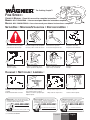
1
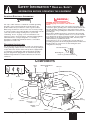
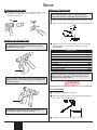
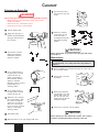
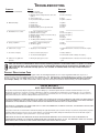
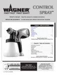
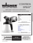
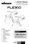
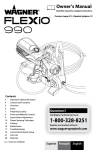
The Painting People™
FINE SPRAY™
OWNER’S MANUAL • Read this manual for complete instructions
MANUEL DE L’UTILISATEUR • Lire ce manuel pour obtenir les instructions complètes
MANUAL DEL PROPRIETARIO • Lea este manual para obtener instrucciones completas
SETUP/USE • MONTAGE/UTILISATION • DISPOSICIÓN/USO :
1
2
Read all warnings!
Lire toutes les mises en garde!
¡Lea todas las advertencias!
Attach and align suction tube
Raccorder et aligner le tube d’aspiration
Conecte y alinee el tubo de succión
3
4
Attach air hose
Raccorder le boyau d'air
Conecte la manguera de aire
Paint preparation
Préparation du produit
Preparación de la material
5
6
7
8
Fill container
Remplir le godet
Llene el recipiente
Adjust spray pattern
Régler la configuration du jet
Ajuste el patrón de dispersión
Adjust material flow
Ajuster le débit du matériel
Ajuste el flujo del material
Practice
Pratiquez
Practique
3
4
CLEANUP • NETTOYAGE • LIMPIEZA :
1
2
Pour remaining material into container
Transvider le reste du produit dans le
contenant
Vierta la material restante en la lata
Spray appropriate cleaner through gun
Faites circuler un dissolvant approprié
dans le pistolet pour le nettoyer
Atomice un solvente apropiado para
limpiar la pistola
Need help? Call us first for answers fast.
Call Wagner toll-free if you have any comments
or problems with this Wagner product.
1-800-328-8251
Wagner Technical Service
Or visit us on the world wide web!
http://www.wagnerspraytech.com
1770 Fernbrook Lane, Minneapolis, MN 55447
0305 •
Form No. 0414852B
Clean all parts
Nettoyer toutes les pièces
Reassemble
Remonter le pistolet
Limpie todos la componentes
Vuelva a armar la pistola
Besoin d'aide? Appelez-nous pour de
réponses rapidas. Telephonez à Wagner sans
frais d'appel si vous avez des commentaires ou
des difficultés relativement à ce produit.
¿Necesita ayuda?
Llámenos primero
para obtener respuestas rápidas. Si tiene
cualquier comentario sobre este producto Wagner
o problemas con el mismo llame gratis a Wagner.
1-800-328-8251
1-800-328-8251
Wagner Technical Service
Ou rendez-nous visite sur le Web!
Wagner Technical Service
¡O visítenos en Internet!
http://www.wagnerspraytech.com
http://www.wagnerspraytech.com
1770 Fernbrook Lane, Minneapolis, MN 55447
1770 Fernbrook Lane, Minneapolis, MN 55447
Español Français English
SAFETY INFORMATION •
READ ALL SAFETY
INFORMATION BEFORE OPERATING THE EQUIPMENT
WARNING
WARNING
HAZARD: EXPLOSION OR FIRE
Solvent and paint fumes can explode or ignite.
Severe injury or property damage can occur.
PREVENTION:
• Provide extensive exhaust and fresh air introduction to keep
the air within the spray area free from accumulation of
flammable vapors.
HAZARD: HAZARDOUS VAPORS
Paints, solvents, insecticides, and other
materials can be harmful if inhaled or come in
contact with the body. Vapors can cause
severe nausea, fainting, or poisoning.
PREVENTION:
• Use a respirator or mask if vapors can be
inhaled. Read all instructions supplied with
the mask to be sure it will provide the
necessary protection.
• Avoid all ignition sources such as static
electric sparks, open flames, pilot lights,
electrical appliances, and hot objects.
Connecting or disconnecting power cords or
working light switches can make sparks.
• Do not smoke in spray area.
• Fire extinguisher must be present and in good working order.
• Place turbine in a well-ventilated area at a maximum distance
from spray area, preferably into a separate, well-ventilated
room. Flammable vapors are often heavier than air. Floor
area must be extremely well-ventilated. The turbine contains
arcing parts that emit sparks and can ignite vapors.
• Follow the material and solvent manufacturer’s warnings and
instructions.
• Do not use materials with a flashpoint below 73°F (22.7°C).
Flashpoint is the temperature that a fluid can produce enough
vapors to ignite.
• Plastic can cause static sparks. Never hang plastic to
enclose the spray area. Do not use plastic drop cloths when
spraying flammable materials.
• Wear protective eyewear.
• Wear protective clothing as required by coating manufacturer.
WARNING
HAZARD: GENERAL
Can cause severe injury or property damage.
PREVENTION:
• Read all instructions and safety precautions before operating
equipment.
• Follow all appropriate local, state, and national codes
governing ventilation, fire prevention, and operation.
• The United States Government Safety Standards have been
adopted under the Occupational Safety and Health Act
(OSHA). These standards, particularly part 1910 of the
General Standards and part 1926 of the Construction
Standards should be consulted.
• Use only manufacturer authorized parts. User assumes all
risks and liabilities when using parts that do not meet the
minimum specifications and safety devices of the turbine
manufacturer.
• Power cord must be connected to a grounded circuit.
• All hoses, swivels, guns and accessories must be rated at or
above 10 PSI.
• Do not spray outdoors on windy days.
• Wear protective clothing to keep paint off skin and hair.
• Never aim spray gun at any part of the body.
• Hose may become hot and cause skin burn.
• Use only Wagner HVLP hose.
WARNING
HAZARD: EXPLOSION HAZARD DUE TO
INCOMPATIBLE MATERIALS.
Will cause property damage or severe injury.
PREVENTION:
• Do not use materials containing bleach or
chlorine.
• Do not use halogenated hydrocarbon solvents such as
bleach, mildewcide, methylene chloride and 1,1,1-trichloroethane. They are not compatible with aluminum.
• Contact your coating supplier about the compatibility of
material with aluminum.
This product is intended for home use.
English
2
© 2003 Wagner Spray Tech. All rights reserved.
SAFETY INFORMATION •
READ ALL SAFETY
INFORMATION BEFORE OPERATING THE EQUIPMENT
IMPORTANT ELECTRICAL INFORMATION
WARNING
CAUTION
DANGER--Improper installation of the
grounding plug can result in a risk of electric
shock.
If repair or replacement of the cord or plug is necessary, do not
connect the green grounding wire to either flat blade terminal. The
wire with insulation having a green outer surface with or without
yellow stripes is the grounding wire and must be connected to the
grounding pin.
Check with a qualified electrician or serviceman if the grounding
instructions are not completely understood, or if you are in doubt
as to whether the product is properly grounded. Do not modify the
plug provided. If the plug will not fit the outlet, have the proper
outlet installed by a qualified electrician.
This product is for use on a nominal 120 volt circuit and has a
grounding plug that looks like the plug illustrated below. Make sure
that the product is connected to an outlet having the same
configuration as the plug.
Use only a 3-wire extension cord that has a 3-blade grounding
plug and a 3-slot receptacle that will accept the plug on the
product. Make sure your extension cord is in good condition.
When using an extension cord, be sure to use one heavy enough
to carry the current your product will draw. An undersized cord will
cause a drop in line voltage resulting in loss of power and
overheating. A 14 or 12 gauge cord is recommended. If an
extension cord is to be used outdoors, it must be marked with the
suffix W-A after the cord type designation. For example, a
designation of SJTW-A would indicate that the cord would be
appropriate for outdoor use.
GROUNDING INSTRUCTIONS
This product must be grounded. In the event of an electrical short
circuit, grounding reduces the risk of electric shock by providing an
escape wire for the electric current. This product is equipped with
a cord having a grounding wire with an appropriate grounding
plug. The plug must be plugged into an outlet that is properly
installed and grounded in accordance with all local codes and
ordinances.
Grounded Outlet
Grounding Pin
Cover for grounded outlet box
COMPONENTS
Spray
gun
Air cap
Nut
Material adjustment
knob
Seal
Air hose
Handle
Nozzle
Trigger
Viscosity
cup
Fluid
container
Filter
housing
Spray gun
holder
ON/OFF
switch
Turbine
© 2003 Wagner Spray Tech. All rights reserved.
3
English
SETUP
ATTACHING
1
THE
AIR HOSE
MATERIAL PREPARATION
Insert the air hose tightly into the connections onto the spray
gun (a) and the turbine (b). The connections can be
positioned as desired.
Before spraying, the material being used may need to be
thinned with the proper solvent as specified by the
material manufacturer. Follow the instructions below.
(a)
1
Stir the spraying material thoroughly before measuring viscosity.
2
Dip the viscosity test cup completely into the spraying material.
3
Hold the test cup up and measure the time in seconds until
the liquid empties out. This time is referred to below as
Runout Time.
(b)
ALIGNING
THE
SUCTION TUBE
If you are going to be spraying in a downward direction,
the angled end of the suction tube should be pointing
toward the front of the gun.
Thinning Chart
Material
1) Oil enamel
2) Oil based primer
3) Oil stain
4) Clear sealer
5) Polyurethane
6) Varnish
7) Lacquer sanding sealer
8) Lacquer
9) Automotive finishes
Runout Time
25-40
30-45
No thinning required
No thinning required
No thinning required
20-50
25-35
25-35
20-40
Material to be sprayed should always be strained to
remove any impurities in the paint which may enter and
clog the system. Impurities in the paint will give poor
performance and a poor finish.
If you are going to be spraying in an upward direction, the
angled end of the suction tube should be pointing toward
the rear of the gun.
WARNING
MATERIAL FLASH POINT MUST BE 73°F (22.7°C) OR HIGHER.
FILL CONTAINER
1
Unscrew the cup from the spray gun.
2
After the material has been properly thinned and strained, fill
the container to the top of the neck.
3
Carefully screw the cup back onto the spray gun.
By pointing the suction tube in the proper direction, you
will not have to refill the container as often.
English
4
© 2003 Wagner Spray Tech. All rights reserved.
SPRAYING
ON/OFF SWITCH
PROPER SPRAYING TECHNIQUE
The ON/OFF switch is located underneath the end of the
carrying handle on the turbine as shown below.
If spraying with an HVLP spray system is new or unfamiliar
to you, it is advisable to practice on a piece of scrap wood
or cardboard before beginning on your intended workpiece.
SURFACE PREPARATION
All objects to be sprayed should be thoroughly cleaned before
spraying material on them. Areas not to be sprayed may, in
certain cases, need to be masked.
SPRAY AREA PREPARATION
When spraying indoors, the spray area must be clean and free of
dust in order to avoid blowing dust onto your freshly sprayed
surface.
ADJUST SPRAY PATTERN
The spray pattern shape is adjusted by turning the ears of
the air cap to either the vertical, horizontal, or diagonal
positions. The positions of the air cap and the
corresponding spray pattern shapes are illustrated below.
Test each pattern and use whichever pattern is suitable for
your application.
HOW
TO
SPRAY PROPERLY
• Position the spray gun perpendicular to and one (1) or more
inches from the spray surface, depending upon the spray
pattern size desired.
• Spray parallel to the surface with smooth passes at a
consistent speed as illustrated below. Doing this will help
avoid irregularities in the finish (i. e. runs and sags).
• Always apply a thin coat of material on the first pass and
allow to dry before applying a second, slightly heavier coat.
Nut
Even coat throughout
Air cap
Round pattern
1 to 12 inches
Correct
Horizontal pattern
Keep stroke smooth and at an even speed
• When spraying, always trigger the spray gun after spray pass
has begun and release trigger before stopping the pass. The
best results occur when making 20-inch passes. Always keep
the gun pointed squarely at the spray surface and overlap
passes slightly to obtain the most consistent and professional
finish possible.
Vertical pattern
WARNING
Light coat
NEVER trigger the gun while adjusting the ears on the air cap.
NEVER point the spray gun at any part of the body.
Heavy coat
Light coat
MATERIAL FLOW ADJUSTMENT
Set the material volume by turning the regulator on the
rear part of the gun spray gun. A scale on the regulator
serves as a guide.
Incorrect
Do not flex wrist while spraying.
When you quit spraying for any length of time, turn the
turbine OFF and place the spray gun into the spray gun
holder on the turbine.
© 2003 Wagner Spray Tech. All rights reserved.
5
English
CLEANUP
CLEANING
THE
SPRAY GUN
9
WARNING
Unscrew the nut and
remove the air cap and
nozzle.
Special cleanup instructions for use with flammable solvents:
• Always flush spray gun preferably outside and at a hose
length from turbine.
• Area must be free of flammable vapors.
• Cleaning area must be well-ventilated.
1
Turn the turbine OFF.
2
Trigger the spray gun so
that the material inside the
spray gun flows back into
the container.
3
Unscrew the container.
Empty any remaining
material back into the
material container.
10 Clean the container,
suction tube, air cap
and nozzle with a
cleaning brush and the
appropriate cleaning
solution.
CAUTION
Never clean nozzle or air holes in the spray gun with sharp
metal objects.
MAINTENANCE
You should inspect the air filter in the turbine to see if it is
excessively dirty. If it is dirty, follow the steps below to
replace it.
4
5
6
7
8
Pour a small amount of
the appropriate cleaning
solution into the cup
(warm, soapy water for
latex materials; mineral
spirits for oil-based
materials). Clean cup and
properly dispose of
cleaning solution.
Pour a small amount of
the appropriate cleaning
solution into the cup.
Attach the cup to the gun,
turn on the turbine, spray
the solution through the
gun for two seconds in a
safe area. Spray again
for two seconds. Properly
dispose of remaining
cleaning solution.
1
Insert a straight-slot screwdriver through one of the slots in
the rear of the turbine.
2
Pry the filter cover from
the turbine.
3
Remove the dirty filter
from the filter cover and
replace with a new one.
The smooth side of the
air filter must be placed
toward the turbine.
4
Secure the cover back onto the turbine.
CAUTION
Turn turbine OFF.
Never operate your unit without the air filter. Dirt could be
sucked in and interfere with the function of the unit.
Wipe the exterior of the cup and gun until clean.
English
6
© 2003 Wagner Spray Tech. All rights reserved.
TROUBLESHOOTING
PROBLEM
A. Little or no material flow
CAUSE
SOLUTION
1. Nozzle clogged.
2. Suction tube clogged.
3. Material volume setting turned too far to the
right (-).
4. Suction tube loose.
5. No pressure build up in container.
1. Clean.
2. Clean.
3. Turn to the left (+).
B. Material leaking
1.
2.
3.
4.
Nozzle loose.
Nozzle worn.
Nozzle seal worn.
Material build-up on air cap and nozzle
1.
2.
3.
4.
Tighten.
Replace.
Replace.
Clean.
C. Atomization is too coarse
1.
2.
3.
4.
5.
6.
Viscosity of material too high.
Material volume too large.
Material volume setting too far to the left (+).
Nozzle clogged.
Air filter clogged.
Too little pressure build-up in container.
1.
2.
3.
4.
5.
6.
Thin.
Turn to the right (-).
Turn to the right (-).
Clean.
Change.
Tighten container.
D. Spray jet pulsates
1. Material in container running out.
2. Air filter clogged.
1. Refill.
2. Change.
E. Pattern runs or sags
1. Applying too much material.
1. Adjust material flow or increase movement of spray
gun.
F. Too much overspray
1. Gun too far from spray object.
2. Too much material applied.
1. Reduce distance.
2. Turn material volume setting to the right (-).
G. Pattern is very light and
splotchy.
1. Moving the spray gun too fast.
1. Adjust material flow or decrease movement of spray
gun.
4. Insert.
5. Tighten container.
Have you tried the recommendations above and are still having problems? In the United States, to speak to a customer
service representative, call our Customer Service at 1-800-328-8251 Monday through Friday between 8:00 AM and 4:30
PM Central time. An automated Self-Help option is also available at 1-800-760-3844, seven days a week, twenty-four
hours a day.
PRODUCT REGISTRATION CARD
Send in your product registration card or register online at www.wagnerspraytech.com. Proper registration will serve as proof of
purchase in the event your original receipt becomes misplaced or lost. Returning this card will expedite the processing of your warranty.
Be sure you write your unit’s date code on the card before sending it. The date code is located underneath the base of your unit
(for example, S087R). The additional information will also help us to develop new products that best meet your needs and desires.
LIMITED WARRANTY
HVLP PAINT SPRAY EQUIPMENT
This product, manufactured by Wagner Spray Tech Corporation (Wagner), is warranted against defects in material and work-manship for one year
following date of purchase if operated in accordance with Wagner’s printed recommendations and instructions. This warranty does not cover damage
resulting from improper use, accidents, user’s negligence or normal wear. This warranty does not cover any defects or damages caused by service or
repair performed by anyone other than a Wagner Authorized Service Center.
ANY IMPLIED WARRANTY OF MERCHANTABILITY OR FITNESS FOR A PARTICULAR PURPOSE IS LIMITED TO ONE YEAR FOLLOWING DATE OF
PURCHASE. WAGNER SHALL NOT IN ANY EVENT BE LIABLE FOR ANY INCIDENTAL OR CONSEQUENTIAL DAMAGES OF ANY KIND, WHETHER
FOR BREACH OF THIS WARRANTY OR ANY OTHER REASON. THIS WARRANTY DOES NOT APPLY TO ACCESSORIES.
THIS PRODUCT IS DESIGNED FOR HOME USAGE ONLY. IF USED FOR COMMERCIAL OR RENTAL PURPOSES, THIS WARRANTY APPLIES ONLY
FOR 30 DAYS FROM DATE OF PURCHASE.
If any product is defective in material and/or workmanship during the applicable warranty period, return it with proof of purchase, transportation prepaid to
any Wagner Authorized Service Center. (Service Center listing is enclosed with this product.) Wagner’s Authorized Service Center will either repair or
replace the product (at Wagner’s option) and return it to you, postage prepaid.
SOME STATES DO NOT ALLOW LIMITATIONS ON HOW LONG AN IMPLIED WARRANTY LASTS OR THE EXCLUSION OF INCIDENTAL OR
CONSEQUENTIAL DAMAGES, SO THE ABOVE LIMITATION AND EXCLUSION MAY NOT APPLY TO YOU. THIS WARRANTY GIVES YOU SPECIFIC
LEGAL RIGHTS, AND YOU MAY ALSO HAVE OTHER RIGHTS WHICH VARY FROM STATE TO STATE.
© 2003 Wagner Spray Tech. All rights reserved.
7
English
PARTS LIST • LISTE
1
2
3
DE PIÈCES
• LISTA DE
PIEZAS
4
5
9
13
6
10
11
7
12
5
8
English
Item
1
2
3
4
5
6
7
8
9
10
11
12
13
Part #
0414351
0414368
0414352
0414353
0414219
0414364
0414363
0414332
0414201
0202303
0414336
9.995-617
0414210
Español
Description
Quantity
Nut . . . . . . . . . . . . . . . . . . . . . . . . . . . .1
Spray cap . . . . . . . . . . . . . . . . . . . . . .1
Nozzle . . . . . . . . . . . . . . . . . . . . . . . . .1
Nozzle seal . . . . . . . . . . . . . . . . . . . . .1
Air hose . . . . . . . . . . . . . . . . . . . . . . . .1
Container seal . . . . . . . . . . . . . . . . . . .1
Suction tube . . . . . . . . . . . . . . . . . . . . .1
Container . . . . . . . . . . . . . . . . . . . . . . .1
Spray gun (includes parts 1-4 and 6-9) .1
Viscosity cup . . . . . . . . . . . . . . . . . . . .1
Plastic container . . . . . . . . . . . . . . . . .1
Air filter* . . . . . . . . . . . . . . . . . . . . . . . .1
Turbine . . . . . . . . . . . . . . . . . . . . . . . . .1
Artículo
1
2
3
4
5
6
7
8
9
10
11
12
13
* Replacement parts available by calling customer service.
Pieza No.
0414351
0414368
0414352
0414353
0414219
0414364
0414363
0414332
0414201
0202303
0414336
9.995-617
0414210
Descripción
Cantidad
Tuerca . . . . . . . . . . . . . . . . . . . . . . . . .1
Tapa de aire . . . . . . . . . . . . . . . . . . . . .1
Boquilla . . . . . . . . . . . . . . . . . . . . . . . .1
Sello de boquilla . . . . . . . . . . . . . . . . .1
Manguera de aire . . . . . . . . . . . . . . . .1
Sello del recipiente . . . . . . . . . . . . . . .1
Tubo de succión . . . . . . . . . . . . . . . . .1
Recipiente . . . . . . . . . . . . . . . . . . . . . .1
Pistola (incluye piezas 1-4, y 6-9) . . . .1
Cubeta de viscosidad . . . . . . . . . . . . .1
Recipiente de la plastico . . . . . . . . . . .1
Filtro de aire* . . . . . . . . . . . . . . . . . . . .1
Turbina . . . . . . . . . . . . . . . . . . . . . . . . .1
* Los repuestos están disponibles llamanado al servicio a clientes.
Français
Article
1
2
3
4
5
6
7
8
9
10
11
12
13
N° de pièce
0414351
0414368
0414352
0414353
0414219
0414364
0414363
0414332
0414201
0202303
0414336
9.995-617
0414210
Description
Qté
Écrou . . . . . . . . . . . . . . . . . . . . . . . . . .1
Capot d’air . . . . . . . . . . . . . . . . . . . . . .1
Buse . . . . . . . . . . . . . . . . . . . . . . . . . . .1
Joint de buse . . . . . . . . . . . . . . . . . . . .1
Flexible d’air . . . . . . . . . . . . . . . . . . . . .1
Joint de godet . . . . . . . . . . . . . . . . . . .1
Tube d’aspiration . . . . . . . . . . . . . . . . .1
Godet . . . . . . . . . . . . . . . . . . . . . . . . .1
Pistolet (inclut des pièces 1-4 et 6-9) .1
Viscosimètre . . . . . . . . . . . . . . . . . . . .1
Godet de plastique . . . . . . . . . . . . . . .1
Filtre à air* . . . . . . . . . . . . . . . . . . . . . .1
Turbine . . . . . . . . . . . . . . . . . . . . . . . . .1
Wagner Spray Tech Corporation
1770 Fernbrook Lane
Plymouth, MN 55447
Tel: 1-800-328-8251
www.wagnerspraytech.com
* On peut obtenir des pièces de rechange en appelant le Service à
la clientèle
20
© 2003 Wagner Spray Tech. All rights reserved.