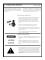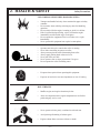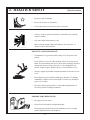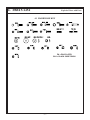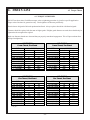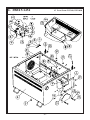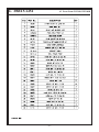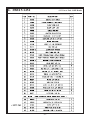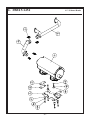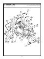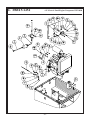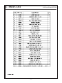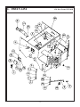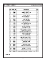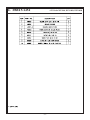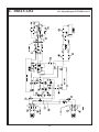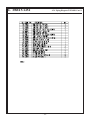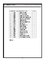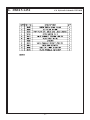
1
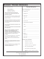
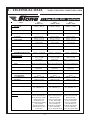
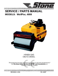
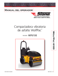
SERVICE / PARTS MANUAL MODELS: WolfPac 3100 WolfPac 3100R (ROPS Option) WolfPac 3100D (Diesel Roller) ASPHALT ROLLER A 100% employee-owned American manufacturer REVISION: E 11/2004 P/N 56608 TABLE of CONTENTS WolfPacTM 3100/WolfPacTM 3100R/WolfPacTM 3100D FOREWORD / WARRANTY INFORMATION .......................................................................... 5 LIMITED WARRANTY ................................................................................................................. 6 SECTION 1 - TECHNICAL DATA ............................................................................................... 7 - 9 1.1 Specifications .................................................................................................................... 8 - 9 1.2 Machine Sound Level Test ................................................................................................ 9 SECTION 2 - HEALTH & SAFETY - Safety Precautions ........................................................... 11 - 17 SECTION 3 - MAINTENANCE ..................................................................................................... 19 - 34 3.1 Important Maintenance ..................................................................................................... 20 3.2 Maintenance Chart ............................................................................................................ 21 3.3 Roll Over Protective Structures (ROPS) .......................................................................... 22 3.3.1 Inspection/Maintenance of ROPS/Seat Belts .................................................. 22 3.4 Additional Service Information ......................................................................................... 22 3.5 Fuel Filter ....................................................................................................................... 22 3.6 Fuel Tank ....................................................................................................................... 22 3.7 Fuel Lines ....................................................................................................................... 23 3.8 Engine Oil And Filter ........................................................................................................ 23 3.9 Air Cleaner ....................................................................................................................... 23 3.10 Spark Plugs (Honda only) ................................................................................................. 23 3.11 Engine RPM ..................................................................................................................... 23 - 24 3.12 Gas Air-Cooling System ................................................................................................... 24 3.13 Checking Coolant Level / Adding Coolant ........................................................................ 24 3.14 Changing Coolant / Checking Radiator Hoses & Clamps ................................................ 24 - 25 3.15 Valve Clearance ................................................................................................................ 25 3.16 Hydraulic Oil .................................................................................................................... 25 3.17 Hydraulic Oil Filter .......................................................................................................... 25 3.18 Hydraulic Breather Cap .................................................................................................... 25 3.19 Grease Fittings .................................................................................................................. 25 3.20 Forward / Reverse / Neutral Adjustment .......................................................................... 26 3.21 Neutral Interlock ............................................................................................................... 26 3.22 Control Cables .................................................................................................................. 26 3.23 Throttle Lever (Honda only) ............................................................................................. 26 - 27 3.24 Parking Brake ................................................................................................................... 27 3.25 Water Tank ....................................................................................................................... 27 3.26 Sprinklers ....................................................................................................................... 27 3.27 Scraper Maintenance / Adjustment ................................................................................... 27 3.28 Eccentrics ....................................................................................................................... 27 3.29 Engine Mounting .............................................................................................................. 27 3.30 Hardware ....................................................................................................................... 27 3.31 Loctite ....................................................................................................................... 27 3.32 Battery ....................................................................................................................... 27 - 28 3.32.1 Servicing Battery ........................................................................................... 28 3.32.2 Battery Installation ......................................................................................... 29 3.33 Jump Starting .................................................................................................................... 29 3.34 Charge System .................................................................................................................. 29 3.35 Switch Box / Fuse ............................................................................................................. 29 3.36 Fuse ....................................................................................................................... 29 3.37 Ignition System ................................................................................................................. 29 3.38 Storage ....................................................................................................................... 29 -3- TABLE of CONTENTS WolfPacTM 3100 / WolfPacTM 3100R 3.39 Troubleshooting ................................................................................................................ 30 - 33 3.40 Service Record .................................................................................................................. 34 SECTION 4 - EXPLODED DIAGRAMS AND PARTS LIST .................................................... 35 - 119 4.1 Hardware Key .................................................................................................................. 37 4.2 Torque Guidelines and Torque Charts .............................................................................. 38 - 39 4.3 Front Frame WP3100, WP3100R.................................................................................... 40 - 41 4.4 Front Frame WP3100D ................................................................................................... 42 - 43 4.5 In-Tank Filter WP3100, WP3100R ................................................................................. 44 - 45 4.6 In-Tank Filter WP3100D ................................................................................................. 46 - 47 4.7 Front Scrapers WP3100, WP3100R, WP3100D ............................................................. 48 - 49 4.8 Hood WP3100, WP3100R, WP3100D ............................................................................ 50 - 51 4.9 Front Drum / Eccentric WP3100, WP3100R, WP3100D ............................................... 52 - 53 4.10 Front Hanger Eccentric WP3100, WP3100R, WP3100D ............................................... 54 - 55 4.11 Front Hanger Drive WP3100, WP3100R, WP3100D ..................................................... 56 - 57 4.12 Power Pack 18 HP Honda ................................................................................................ 58 - 59 4.13 Exhaust Honda ................................................................................................................. 60 - 61 4.14 Power Pack Kubota WP3100D........................................................................................ 62 - 63 4.15 Electric Panel /Engine Component WP3100D ................................................................. 64 - 65 4.16 Pump Assembly WP3100D .............................................................................................. 66 - 67 4.17 Air Filter WP3100D ........................................................................................................ 68 - 69 4.18 Pivot WP3100, WP3100R, WP3100D ............................................................................ 70 - 71 4.19 Rear Frame WP3100 ....................................................................................................... 72 - 73 4.20 Rear Frame WP3100R ..................................................................................................... 74 - 75 4.21 Rear Frame WP3100D .................................................................................................... 76 -77 4.22 Brake WP3100, WP3100R, WP3100D ........................................................................... 78 - 79 4.23 Battery / Seat / Covers WP3100 ...................................................................................... 80 - 81 4.24 Battery / Seat / Covers WP3100R, WP3100D ................................................................ 82 - 83 4.25 Steering Console WP3100 ............................................................................................... 84 - 85 4.26 Steering Console WP3100R ............................................................................................. 86 - 87 4.27 Steering Console WP3100D ............................................................................................ 88 - 89 4.28 Rear Scrapers WP3100, WP3100R, WP3100D .............................................................. 90 - 91 4.29 Rear Drum WP3100, WP3100R, WP3100D ................................................................... 92 - 93 4.30 Water Tank WP3100, WP3100R ..................................................................................... 94 - 95 4.31 Water Tank WP3100D ..................................................................................................... 96 - 97 4.32 ROPS WP3100R, WP3100D .......................................................................................... 98 - 99 4.33 Piping Diagram WP3100, WP3100R .............................................................................. 100 - 103 4.34 Piping Diagram WP3100D .............................................................................................. 104 - 107 4.35 Hydraulic Schematic WP3100, WP3100R ...................................................................... 108 - 109 4.36 Hydraulic Schematic WP3100D ...................................................................................... 110 - 111 4.37 Wire Schematic ROPS Unit Only WP3100, WP3100R .................................................. 112 - 113 4.38 Wire Schematic Non-ROPS Unit Only WP3100, WP3100R .......................................... 114 - 115 4.39 Electrical Schematic WP3100D ....................................................................................... 116 - 117 4.40 Decal Identification .......................................................................................................... 118 - 119 CALIFORNIA PROPOSITION 65 WARNING ........................................................................... 123 -4- Foreword / Warranty Information Warranty Information These instructions include: Safety regulations Operating instructions Maintenance instructions Please enter the following data. This will help expedite any service or warranty work. These instructions have been prepared for operation on the construction site and for the maintenance engineer. These instructions are intended to simplify operation of the machine and to avoid malfunctions through improper operation. Observing the maintenance instructions will increase the reliability and service life of the machine when used on the construction site and reduce repair costs and downtimes. 1. Machine S/N: ________________________________ 2. 3. VIN: _______________________________________ 4. Purchase Date: _______________________________ 5. Dealer/Distributor Information: Name: ______________________________________ Address: ____________________________________ Only operate the machine as instructed and follow these instructions. Stone Construction Equipment, Inc. is not liable for the function of the machine when used in an improper manner and for other than the intended purpose. Operating errors, improper maintenance and the use of incorrect operating materials are not covered by the warranty. Engine Type: ________________________________ Engine S/N: _________________________________ Always keep these instructions at the place of use of the machine. Observe the safety regulations as well as the guidelines of the civil engineering trade association. Observe the safety rules for the operation of road rollers and compactors and the pertinent regulations for the prevention of accidents. Machine Type: _______________________________ ___________________________________________ Phone #: ____________________________________ Fax #: ______________________________________ 6. Battery Manufacturer: _______________________________ Battery Type: ________________________________ Battery S/N: _________________________________ Location of above information: The above information does not extend the warranty and liability conditions of business of Stone Construction Equipment, Inc. 1. Information on S/N tag. 2. Information on engine tag. 3. Information on S/N tag - if applicable. 4. Date you purchased machine. 5. Dealer machine was purchased from. 6. Information on battery and battery warranty card. Stone Construction Equipment, Inc. P.O. Box 150, Honeoye, New York 14471 Phone: (800) 888-9926 Fax: (585) 229-2363 -5- L i m i t e d W a r r a n t y The Manufacturer warrants that products manufactured shall be free from defects in material and workmanship that develop under normal use for a period of 90 days for concrete vibrators and electric pumps, one year for Rhino®, Bulldog®, WolfPac Rollers, trowels, Stompers®, saws, forward plates, engine powered pumps, Lift Jockey, Mortar Buggy and 6 months for all other products from the date of shipment. The foregoing shall be the exclusive remedy of the buyer and the exclusive liability of the Manufacturer. Our warranty excludes normal replaceable wear items, i.e. gaskets, wear plates, seals, Orings, V-belts, drive chains, clutches, etc. Any equipment, part or product which is furnished by the Manufacturer but manufactured by another, bears only the warranty given by such other manufacturer. (The Manufacturer extends the warranty period to “Lifetime” for the drum bearings and seals for the mortar mixers, and agrees to furnish, free of charge, the bearings and seals only upon receipt of the defective parts. The warranty is two years for eccentric bearings on the forward plate compactors, mortar and plaster mixer drums, trowel gearboxes, three years on the Bulldog trench roller microprocessor (ECIB) and five years on the Bulldog trench roller eccentric bearings.) A Warranty Evaluation Form must accompany all defective parts. Warranty is voided by product abuse, alterations, and use of equipment in applications for which it was not intended, use of non-manufacturer parts, or failure to follow documented service instructions. The foregoing warranty is exclusive of all other warranties whether written or oral, expressed or implied. No warranty of merchantability or fitness for a particular purpose shall apply. The agents, dealer and employees of Manufacturer are not authorized to make modification to this warranty, or additional warranties binding on Manufacturer. Therefore, additional statements, whether oral or written, do not constitute warranty and should not be relied upon. The Manufacturer’s sole responsibility for any breach of the foregoing provision of this contract, with respect to any product or part not conforming to the Warranty or the description herein contained, is at its option (a) to repair, replace or refund such product or parts upon the prepaid return thereof to location designated specifically by the Manufacturer. Product returns not shipped prepaid or on an economical transportation basis will be refused (b) as an alternative to the foregoing modes of settlement - the Manufacturer’s dealer to repair defective units with reimbursement for expenses, except labor, and be reviewed with the Manufacturer prior to repair. A Warranty Evaluation Form must accompany all warranty claims. Except as set forth hereinabove and without limitation of the above, there are no warranties or other affirmations which extends beyond the description of the products and the fact hereof, or as to operational efficiency, product reliability or maintainability or compatibility with products furnished by others. In no event whether as a result of breach of contract or warranty or alleged negligence, shall the Manufacturer be liable for special or consequential damages including but not limited to: Loss of profits or revenues, loss of use of the product or any associated product, cost of capital, cost of substitute products, facilities or services or claims of customers. No claim will be allowed for products lost or damaged in transit. Such claims should be filed with the carrier within fifteen days. Effective January 2004. Stone Construction Equipment, Inc. • 8662 Main Street, P. O. Box 150 • Honeoye, NY 14471-0150 Phone: 1-800-888-9926 • 1-585-229-5141 Fax: 1-585-229-2363 www.stone-equip.com • e-mail: [email protected] -6- P/N 51018 G-7524 01/2004 1. TECHNICAL DATA -7- 1. TECHNICAL DATA ® Model WolfPac 3100/WolfPac 3100R/WolfPac 3100D 1.1 Stone WolfPac 3100 - Specifications Stone Wolf Pac 3100 Stone Wolf Pac 3100R Stone Wolf Pac 3100D 2296 lbs. / 1041 kg. 2396 lbs. / 1087 kg. 2602 lbs. / 1180 kg. Operating Weight 2945 lbs. / 1336 kg. 3045 lbs. / 1381 kg. 3263 lbs. / 1480 kg. B allasted Weight 3154 lbs. / 1431 kg. 3254 lbs. / 1476 kg. 3472 lbs. / 1575 kg. L xW xH 82 x 39 x 58 in. 208 x 99 x 147 cm. 35.4 in. / 89.9 cm. 82 x 39 x 94 in. 208 x 99 x 239 cm. 35.4 in. / 89.9 cm. 82 x 39 x 94 in. 208 x 99 x 239 cm. 35.4 in. / 89.9 cm. Drum Diameter 22 in. / 56 cm. 22 in. / 56 cm. 22 in. / 56 cm. Side Wall Clearance 1.8 in. / 4.6 cm. 1.8 in. / 4.6 cm. 1.8 in. / 4.6 cm. Curb Clearance 16 in. / 41 cm. 16 in. / 41 cm. 16 in. / 41 cm. 3 in./9in. – 8cm./23cm. 3 in./9in. – 8cm./23cm. 3 in./9in. – 8cm./23cm. 18 hp / 13.4 kW Honda Twin 8 gallons / 30 liters 18 hp / 13.4 kW Honda Twin 8 gallons / 30 liters 20 hp / 14.9 kW Kubota 3 Cylinder Diesel 8 gallons / 30 liters Drive Hydrostatic Double Drum Hydrostatic Double Drum Hydrostatic Double Drum Steering Center-Point Articulating Hydrostatic 40 gallons / 151 liters Center-Point Articulating Hydrostatic 40 gallons / 151 liters Center-Point Articulating Hydrostatic 40 gallons / 151 liters Front 3000 lbs. / 13.3 kN Front 3000 lbs. / 13.3 kN Front 3000 lbs. / 13.3 kN 3900 vpm / 65 Hz 3900 vpm / 65 Hz 3900 vpm / 65 Hz 30% 30% 30% Outside Turning Radius In - 6.6 ft. Out - 9.5 ft. In - 2.0m. Out - 2.9 In - 6.6 ft. Out - 9.5 ft. In - 2.0m. Out - 2.9 In - 6.6 ft. Out - 9.5 ft. In - 2.0m. Out - 2.9 Infinitely Variable Speed 0 - 5.0 mph / 0 – 8.0 km/hr 0 - 5.0 mph / 0 – 8.0 km/hr 0 - 5.0 mph / 0 – 8.0 km/hr Hour Meter, Ignition Switch, Neutral Ignition Interlock, Transport Link, Lifting P oints, AntiVandal P rotection, Adjustable Safety Sliding Seat, Hydraulic Transmission By-P ass, Hydraulic P ressure Test P oints, Horn ROP S, Hour Meter, Ignition Switch, Neutral Ignition Interlock, Transport Link, Lifting P oints, Anti-Vandal P rotection, Adjustable Safety Sliding Seat, Hydraulic Transmission By-P ass, Hydraulic P ressure Test P oints, Horn ROP S, Hour Meter, Ignition Switch, Neutral Ignition Interlock, Transport Link, Lifting P oints, Anti-Vandal P rotection, Adjustable Safety Sliding Seat, Hydraulic Transmission By-P ass, Hydraulic P ressure Test P oints, Horn Dimensions Dry Weight Drum Width Front/Rear Wall Clearance Operating System Engine Fuel Capacity Water Tank Capacity Perf ormance Vibrating Drum Centrif ugal Force Frequency G radeability Standards -8- 1. TECHNICAL DATA WolfPac 3100/WolfPac 3100R/WolfPac 3100D 1.1 SPECIFICATIONS Continued BRAKES: SERVICE PARKING Hydrostatic Manual operation friction RECOMMENDED FUEL Gasoline 86 octane minimum (Honda) No. 2 diesel fuel (Kubota) ELECTRIC 12 volt system battery BCI group 70 550 cca 25 amp charge system (Honda) 40 amp charge system (Kubota) HYDRAULIC OIL Mobil Drive Clean Oil 20W-50 (V.1. 124) 162 cST at 40 degrees Celsius 18.1 cST at 100 degrees Celsius Capacity 12 gallons /45.4 liters ECCENTRIC OIL Mobil Delvac 1230 30W, 12 ounces (.36 liters) ENGINE OIL Mobil Delvac 1200 10W30, (check engine manual for volume capacity) SPARK PLUGS NGK BPR6ES, NIPPONDENSO W20EPR-U gap .028-.031 inches (.70-.80 mm) (Honda) GREASE FITTINGS Mobilgrease XHP222 (NLGI 2EP Lithium Complex) BATTERY 12 Volt Standard duty battery BCI group 70 550CCA 1.2 MACHINE SOUND LEVEL TEST Machine Type: Sound Level Meter Calibration Date: Meter Type: Test Date: Test Conditions: Temperature: Ambient Sound: Soil Condition: Engine Speed: Frequency: Test Site: Sound Level at Operator Position: WP3100 (Honda) December 19, 1995 Simpson Model 886-2 Type 2 December 19, 1995 60 degrees Fahrenheit 60 dba slow mode Silts and clays 3400 rpm 3900 rpm Honeoye, New York USA 89 dba 93 dba with vibe -9- 2. HEALTH & SAFETY - 11 - 2. HEALTH & SAFETY Before using this equipment, study this entire manual to become familiar with its operation. Do not allow untrained or unauthorized personnel, especially children, to operate this equipment. Use only factory authorized parts for service. Safety Precautions When warning decals are destroyed or missing, contact the Manufacturer immediately at 1-800-888-9926 for replacement. For the safety of yourself and others, it is imperative that the following rules are observed. Failure to do so may result in serious injury or death. FOLLOW SAFETY INSTRUCTIONS Carefully read all safety messages and decals in this manual and on your machine safety signs. Keep decals in good condition. Replace missing or damaged decals. Be sure new equipment components and repair parts include the current safety signs. Replacement safety signs and decals are available through your dealer. Learn how to operate the machine and how to use controls properly. Do not let anyone operate without instruction. Keep your machine in proper working condition. Unauthorized modifications to the machine may impair the function and/or safety and affect machine life. If you do not understand any part of this manual and need assistance, contact your dealer. UNDERSTAND SIGNAL WORDS A signal word DANGER, WARNING, or CAUTION is used with the safety-alert symbol. DANGER identifies the most serious hazards. DANGER or WARNING safety signs are located near specific hazards. General precautions are listed on CAUTION safety signs. CAUTION also calls attention to safety messages in this manual. This notation appears before warnings in the text. It means that the step which follows must be carried out to avoid the possibility of personal injury or death. These warnings are intended to help the technician avoid any potential hazards encountered in the normal service procedures. We strongly recommend that the reader takes advantage of the information provided to prevent personal injury or injury to others. - 12 - 2. HEALTH & SAFETY Safety Precautions USE COMMON SENSE WHEN HANDLING FUELS Transport and handle fuel only when contained in approved safety container. Do not smoke when refueling or during any other fuel handling operation. Do not refuel while the engine is running or while it is still hot. If fuel is spilled during refueling, wipe it off from the engine immediately and discard the rag in a safe place. Do not operate the equipment if fuel or oil leaks exist - repair immediately. Never operate this equipment in an explosive atmosphere. Operator must always be seated when roller is running. Never allow more than one person on roller. Always turn engine off before dismounting from roller. Always apply parking brake when not in use. Never park roller on a hill. Never operate roller on slope greater than 15 degrees. Do not operate the roller in standing water. Ear protection required when operating this equipment. Exposure to loud noise can cause impairment or loss of hearing. HOT SURFACES Muffler, engine, and engine shroud may be hot. Allow all components in the engine compartment to cool before performing any service work. Never operate unit in a poorly ventilated or enclosed area. Avoid prolonged breathing of exhaust gases. Engine exhaust fumes can cause sickness or death. - 13 - 2. HEALTH & SAFETY Safety Precautions Qualified personnel only. No untrained operators. Serious injury may occur. Users must be trained to operate this roller. Read the Operator's Manual and Engine Owner's Manual. Learn to operate this roller safely. Do not articulate on grades larger than 15o, roller may tip over. Do not operate across the sides of hills, roller may tip over. Do not operate at the edge of mats or roads, roller may tip over. Do not stand, be seated when roller is running. Do not park the roller on hills. Always turn off engine and apply brake before dismounting. Hydraulic system produces high pressures--incorrect hose replacement can cause serious personal injury. When performing service, refer to Operator's Manual for hose identification and connections. Caution: Escaping hydraulic fluid under pressure can have sufficient force to penetrate the skin, causing serious personal injury. Hydraulic fluid escaping under pressure from a very small hole can be almost invisible. Use a piece of cardboard or wood to search for possible leaks. Never use your hands to detect pressure leaks. Hydraulic tank temperature can reach 180o F maximum. Pressurized release of fluids from hydraulic system can cause serious burns. Shut off engine. Only remove filler cap when cool enough to touch with bare hands. Slowly loosen cap to first stop to relieve pressure before removing completely. Never perform any work on the roller while it is running. Before working on the roller, stop the engine and disconnect the spark plug wire(s) to prevent accidental starting, block drums to prevent rolling. Keep engine cover closed during the operation. Keep hands, clothing and jewelry away from all moving parts. Keep all guards in place. - 14 - 2. HEALTH & SAFETY Safety Precautions Keep feet clear of all drums. Keep work area free of bystanders. For foot protection, wear steel toe shoes or toe pads. Caution: Keep away from the machines articulation area when the engine is running. Only start engine from operators seat. Before starting machine, make sure that there are no persons or obstacles near or under machine. PRACTICE SAFE MAINTENANCE Understand service procedure before doing work. Keep area clean and dry. Never lubricate, service or adjust machine while it is moving. Keep hands, feet, and clothing from power-driven parts. Disengage all power and operate controls to relieve pressure. Lower equipment to the ground. Stop the engine. Remove the key. Allow machine to cool. Securely support any machine elements that must be raised for service work. Keep all parts in good condition and properly installed. Fix damage immediately. Replace worn or broken parts. Remove any buildup of grease, oil, or debris. Disconnect battery ground cable (-) before making adjustments on electrical systems or welding on machine. PREPARE FOR EMERGENCIES Be prepared if a fire starts. Keep a first aid kit and fire extinguisher handy. Keep emergency numbers for doctors, ambulance service, hospital, and fire department near your telephone. - 15 - 2. HEALTH & SAFETY Safety Precautions Starting fluid (ether) is highly flammable, do not use or an explosion or fire may result. WEAR PROTECTIVE CLOTHING Wear close fitting clothing and safety equipment appropriate to the job. Prolonged exposure to loud noise can cause impairment or loss of hearing. Wear a suitable hearing protective device such as earmuffs or earplugs to protect against objectionable or uncomfortable loud noises. Operating equipment safely requires the full attention of the operator. Do not wear radio or music headphones while operating machine. PREVENT BYPASS STARTING Avoid possible injury or death from engine runaway. Do not start engine by shorting across starter terminal. Engine will start with PTO engaged if normal circuitry is bypassed. Start engine only from operators station with PTO disengaged or in neutral. DISPOSE OF WASTE PROPERLY Improperly disposing of waste can threaten the environment and ecology. Potentially harmful waste used with equipment include such items as oil, fuel, coolant, brake fluid, filters, and batteries. Use leakproof containers when draining fluids. Do not use food or beverage containers that may mislead someone into drinking from them. Do not pour waste onto the ground, down a drain, or into any water source. Air conditioning refrigerants escaping into the air can damage the Earths atmosphere. Government regulations may require a certified air conditioning service center to recover and recycle used air conditioning refrigerants. Inquire on the proper way to recycle or dispose of waste from your local environmental or recycling center. - 16 - 2. HEALTH & SAFETY Safety Precautions Battery Charging Read and understand the Maintenance Section of this manual before attempting to charge the battery. Before using a charger, read all the manufacturers’ instructions for, and caution markings on (1) charger and (2) battery. Wear personal protective equipment including gloves and complete eye protection that protects eyes from all angles. Never work alone with electrical equipment. Make sure that someone is nearby to give assistance if you need help. Reduce explosive gas (hydrogen). Batteries give off explosive gases when charging and serious injuries can occur. Be sure the area around the battery is clean and well ventilated before and during the charging process. Avoid flames and sparks near the battery. Do not smoke or weld near the battery. Keep flames, matches, lighters, cigarettes or other ignition sources away from the battery. Use only cables and clamps that are well insulated and in good condition to make connections between battery and charger. Exercise caution in using metal tools on or near the battery to reduce the risk of short circuits that may cause battery explosions. Do not place tools on top of the battery. Avoid overcharging batteries. Some chargers can overcharge a battery if left connected for an extended period of time resulting in loss of water and creation of hydrogen gas. Rising battery temperature and vigorous gassing are clear indications of excessive charging which may reduce battery life. So called FAST (also known as High Rate or Boost) chargers should be used with caution. Do not use a fast charger for more than 30 minutes on any battery. In very cold weather, a discharged battery may freeze. Never charge a frozen battery. Gases may form which can crack the case and release battery acid. Avoid contact with corrosion due to battery acid. Battery posts may have acid corrosion that may be harmful to eyes and skin. If the battery is to be removed and/or replaced, always use a battery carrier. Carrying the battery by hand may put pressure on its ends, causing battery acid to be forced out the vent caps. Avoid tipping the battery, which may cause the release of battery acid through the vent caps. Avoid dropping the battery. Batteries can be heavy and may cause injuries if dropped. Dropping the battery can crack the case and release battery acid. Be sure to wash your hands with soap and water after servicing or handling the battery. This will help neutralize any acid you may have contacted. Always have plenty of fresh water and soap nearby in case battery acid contacts the eyes, skin or clothing. If battery acid contacts the skin or clothing, wash immediately with soap and water. If battery acid enters the eye, immediately flood eye with cold running water for at least fifteen (15) minutes and get medical help immediately. - 17 - 3. MAINTENANCE - 19 - 3. MAINTENANCE F WolfPac 3100/WolfPac 3100R/WolfPac 3100D 3.1 IMPORTANT The person attempting any of the following maintenance tasks must be authorized to do so and have read and understood all sections within this manual. - 20 - 3. MAINTENANCE WolfPac 3100/WolfPac 3100R/WolfPac 3100D 3.2 MAINTENANCE CHART - 21 - 3. MAINTENANCE WolfPac 3100/WolfPac 3100R/WolfPac 3100D 3.3 ROLL OVER PROTECTIVE STRUCTURES (ROPS) Proper inspection and maintenance procedures can ensure that the ROPS will perform the lifesaving function they are designed for and expected to do. Make regular, periodic inspections to ensure that the ROPS are damage-free and thus capable of functioning in an upset. Generally ROPS structures are not intended as external load carrying members and must not be used to mount attachments such as pull hooks, winches, side brooms, etc. without the manufacturers approval. Modifications to basic design should be avoided as recertification is required. 3.3.1 Inspection/Maintenance of ROPS/Seat Belts Scheduled, frequent visual checks of mounting hardware by the operator or service personnel are recommended. Inspection with regular service intervals is suggested. During the inspection check for the following: Worn, damaged, or missing resilient mounts. Excessive motion or rattling during operation are indications of a problem. Loose, missing, or damaged mounting hardware (bolts, nuts, washers, etc.). Bolts should be checked for proper torque. Cracks in ROPS structure and mounting system. The machine should be cleaned, as necessary, to allow inspection for cracks in the structure and mounting system. Rust lines should be taken as indications of cracks and verified by inspection. Some cracks will badly affect the ROPS function. If in doubt, consult the manufacturer. Corrosion. Extensive paint peeling and rust should be noted and corrective action taken. Seat belt. The presence and operability of a seat belt should be noted. The belt should be clean, free of dirt and grease, and the latch should function smoothly. The structure should be inspected following a roll over, collision, or fire. WARNING DO NOT REPAIR, MODIFY, OR ADD ATTACHMENTS TO ROPS UNLESS AUTHORIZED IN WRITING BY THE MANUFACTURER. 3.4 ADDITIONAL SERVICE INFORMATION This is not a detailed engine service manual. If you want more detailed service information refer to engine manuals: 56237 Manual Engine Gx610/Gx620 56238 Manual Shop Gx610/Gx620 Kubota Diesel Engine Owners Manual (provided with WP3100D) WARNING BEFORE MAKING ANY ADJUSTMENTS, BE SURE THE ROLLER IS PARKED ON LEVEL GROUND, PARKING BRAKE IS ON AND DRUMS ARE BLOCKED. DISCONNECT BATTERY TO AVOID ACCIDENTAL IGNITION OF ENGINE. SEVERE PERSONAL INJURY MAY OCCUR. IMPORTANT: Read Honda or Kubota Emission Warranty Statement and Engine Manual before operating or performing maintenance. 3.5 FUEL FILTER Clean fuel filter pot on Kubota engine to prevent dirt intrusion. Remove the Honda control cover and inspect fuel filter, replace if water or dirt sediment is found. Inline filter should be replaced at scheduled maintenance. 3.6 FUEL TANK Drain and flush the fuel tank yearly. - 22 - 3. MAINTENANCE WolfPac 3100/WolfPac 3100R/WolfPac 3100D 3.7 FUEL LINES Inspect fuel line condition and clamps weekly. Replace fuel lines every 2 years. On diesel air cleaner, open evacuator valve once a week to rid air cleaner of large particles of dust and dirt. Replace elements if damaged or excessively dirty. 3.10 SPARK PLUGS (Honda only) 3.8 ENGINE OIL AND FILTER Replace oil at 20 hours, then change oil every 100 hours. Change the oil filter every 200 hours. Recommended spark plug: BPR6ES (NGK) W20EPR-U (NIPPONDENSO) Remove the oil filler cap, drain bolt or cap (and oil filter when required). Drain oil into a suitable container. To ensure proper engine operation, the spark plug must be properly gapped and free of deposits. Clean and install the drain bolt or cap, tighten securely. When required install new oil filter, lightly oil filter seal. Fill with the recommended oil, fill to the upper limit mark on the dipstick, and tighten the oil filler cap securely. Run engine for 2 3 minutes, stop engine and check oil level and check for leaks. NOTICE: DO NOT overfill engine oil reservoir. It may cause erratic engine operation. Please dispose of used motor oil and filter in a manner that does not harm the environment. Under heavy loads, change engine oil and filter more frequently. 3.9 AIR CLEANER Clean and replace at scheduled maintenance. Clean engine before removing spark plugs. Visually inspect the spark plug, discard if insulator or tip is damaged. Check that the spark plug washer is in good condition. If spark plug is to be reused, clean with a wire brush and set plug gap .028 - .031in (.70 - .80mm). Thread the spark plug in by hand to prevent cross threading. After the spark plug is seated, tighten with a spark plug wrench to compress the washer. If installing a new spark plug, tighten 1/2 turn after the spark plug seats to compress the washer. If reinstalling a used spark plug, tighten 1/8 1/4 turn after the spark plug seats to compress the washer. NOTICE: The spark plug must be securely tightened. An improperly tightened spark plug can become very hot and may cause engine damage. Foam Pre-cleaner: Clean in warm soapy water, rinse and dry thoroughly. Apply oil to the foam and squeeze out excess oil. The engine will smoke if too much oil is left in the foam. Paper Element: Tap the element lightly on a hard surface to remove excess dirt or blow pressurized air (30 psi max.) through the filter from the air cleaner cover side. Do not brush the dirt off. Use only the recommended spark plug or equivalent. A spark plug that has an improper heat range may cause engine damage. 3.11 ENGINE RPM Start the engine and allow it to warm up to normal operating temperature, check the idle speed 1,400 + 100, and adjust idle stop screw as required on Honda. For Kubota, check idle speed at 1200 +/- 50. - 23 - 3. MAINTENANCE WolfPac 3100/WolfPac 3100R/WolfPac 3100D Check the full speed, Honda and Kubota 3,400 +/- 100 and adjust full speed stop screw as required. WARNING TO AVOID PERSONAL INJURY: DO NOT STOP ENGINE SUDDENLY, STOP IT AFTER ABOUT 5 MINUTES OF UNLOADED IDLING. Notice the idle and full speed RPM setting should not be modified or eccentric system may be damaged. See Eccentric for proper operating speed. 3.12 GAS AIR-COOLING SYSTEM WORK ONLY AFTER LETTING THE The machine should be cleaned at scheduled maintenance. This should include cleaning the air inlet screens and the engine cooling fins. Wash machine with warm soapy water, rinse off mud and dirt with water, and use pressurized air (30-psi max.) to blow dirt and debris from engine. 3.13 CHECKING COOLANT LEVEL/ ADDING COOLANT The Kubota diesel engine is equipped with a radiator and reserve tank. Check coolant level daily. Level should be between the full and low marks on the reserve tank. When coolant level drops due to evaporation, add water only up to the full level. ENGINE AND RADIATOR COOL OFF COMPLETELY (MORE THAN 30 MINUTES AFTER IT HAS BEEN STOPPED). DO NOT REMOVE THE RADIATOR CAP WHILE COOLANT IS HOT. WHEN COOL TO THE TOUCH, ROTATE CAP TO THE FIRST STOP TO ALLOW EXCESS PRESSURE TO ESCAPE. THEN REMOVE CAP COMPLETELY. IF OVERHEATING SHOULD OCCUR, STEAM MAY GUSH OUT FROM THE RADIATOR OR RESERVE TANK; SEVER BURNS COULD RESULT. 3.14 CHANGING COOLANT/ CHECKING RADIATOR HOSES & CLAMPS WHEN USING ANTI-FREEZE, PUT ON SOME PROTECTION SUCH AS RUBBER GLOVES. To drain coolant, always open both drain cocks and simultaneously open the radiator cap as well. Remove overflow pipe to drain reserve tank. The radiator capacity is approximately .82 gallons (3.1 liters). Use clean, fresh water and 50% anti-freeze to fill radiator. Check radiator hoses and clamps every 200 hours for leaks or cracks. Replace every 2 years or earlier if hoses are swollen or cracked. IF YOU SHOULD DRINK ANTI-FREEZE, THROW UP AT ONCE AND TAKE MEDICAL ATTENTION. WHEN ANTI-FREEZE COMES IN CONTACT WITHTHE SKIN OR CLOTHING, WASH IT OFF IMMEDIATELY. WARNING ENGINE IS EQUIPPED WITH HIGH TEMPERATURE SHUT DOWN. ROLLER WILL SHUT DOWN IF RADIATOR TEMPERATURE EXCEEDS 226° F (108° C) DO NOT MIX DIFFERENT TYPES OF ANTI-FREEZE. KEEP FIRE AND CHILDREN AWAY FROM ANTI-FREEZE. BE MINDFUL OF THE ENVIRONMENT AND ECOLOGY. BEFORE DRAINING ANY FLUIDS, FIND OUT THE CORRECT - 24 - 3. MAINTENANCE WolfPac 3100/WolfPac 3100R/WolfPac 3100D WAY OF DISPOSING BY CHECKING WITH LOCAL CODES. Add fresh hydraulic oil until level is visible in the sight gauge. A 1/4 1/2 air bubble will be seen at the top of the gauge. Install and tighten return filter cap. Idle engine 2-3 minutes, stop engine and check for proper hydraulic oil level and leaks. ALSO, OBSERVE THE RELEVANT ENVIRONMENTAL PROTECTION REGULATIONS WHEN DISPOSING OF OIL, FUEL, COOLANT, BRAKE FLUID, FILTERS AND BATTERIES. 3.15 VALVE CLEARANCE CAUTION: If hoses, filter and/or hydraulic components were changed, start the engine and purge the air from the system prior to checking the oil level. To do this, idle the engine for three minutes with control lever in neutral position. Slowly engage forward to reverse. This allows fluid to replace air introduced with the filter change. If this procedure is not followed, partial or complete failure of the pump may result. Due to special tool requirements and training, an authorized engine dealer should perform this service unless the owner has the proper tools and proper shop manuals. 3.16 HYDRAULIC OIL WARNING NOTE: When changing the hydraulic oil, it is recommended to also change the hydraulic oil filter. ESCAPING HYDRAULIC FLUID UNDER PRESSURE CAN HAVE SUFFICIENT FORCE TO PENETRATE THE SKIN, CAUSING SERIOUS PERSONAL INJURY. 3.17 HYDRAULIC OIL FILTER HYDRAULIC FLUID ESCAPING UNDER PRESSURE FROM A VERY SMALL HOLE CAN BE ALMOST INVISIBLE. USE A PIECE OF CARDBOARD OR WOOD TO SEARCH FOR POSSIBLE LEAKS. NEVER USE YOUR HANDS TO DETECT PRESSURE LEAKS. IF YOU ARE INJURED BY ESCAPING HYDRAULIC FLUIDS, SEE A DOCTOR AT ONCE. SERIOUS INFECTION OR REACTION CAN DEVELOP IF PROPER MEDICAL TREATMENT IS NOT ADMINISTERED IMMEDIATELY. Do not mix hydraulic oils. Check oil level daily, replace hydraulic oil every 800 hours. Remove return filter cap slowly. Remove drain plug and drain into suitable container. Clean drain plug, apply thread sealant to the plug, install and tighten. Replace every 100 hours or when clog indicator needle is between 2 and 5. Never let the filter be completely clogged. CAUTION: Never overfill the hydraulic tank. Use the sight gage located on the hydraulic tank. A 1/4-1/2 air bubble will be seen at the top of the gauge showing the fluid level. Before disconnecting any hydraulic lines, be sure engine is shut off and relieve all pressure. Before applying pressure to system, be sure all connections are tight and lines, fittings and hoses are not damaged. 3.18 HYDRAULIC BREATHER CAP Replace every 800 hours or yearly. To replace breather, pry it out with a flat head screw driver. To install breather, push it in with fingers. 3.19 GREASE FITTINGS Use a grease gun to grease fittings. Remove the blue protection cap off fitting before greasing. Hinge (4) fittings Left rear bearing (1) fitting - 25 - 3. MAINTENANCE WolfPac 3100/WolfPac 3100R/WolfPac 3100D 3.20 FORWARD/REVERSE/NEUTRAL ADJUSTMENT 3.22 CONTROL CABLES Forward/reverse, brake, throttle, and choke. Lubricate all cable ends every 200 hours with penetrating oil. The forward/reverse lever should be aligned with NEUTRAL on the console when the roller is not moving forward or backward with the engine running. If the lever is not aligned, adjust it as follows: Shut off the engine with the forward/reverse lever left in operating neutral position, the position when the roller moves neither forward nor reverse. Apply the parking brake. Open the engine hood of the machine. Disconnect the linkage from the hydrostatic transmission from the clevis. Do this by removing the lock nut from the clevis pin and removing the pin. Now screw clevis in or out to adjust. Secure the clevis to the transmission lever with the clevis pin, secure with the lock nut and tighten clevis nut. WARNING DO NOT ADJUST THE CONTROL CABLE WITH THE POWER ON OR THE ENGINE RUNNING. SERIOUS INJURY OR DEATH COULD RESULT. A GRADUAL OR SUDDEN INCREASE IN THE NO-LOAD FRICTION (CABLE DISCONNECT AT BOTH ENDS) OF A CONTROL CABLE IS AN INDICATION OF A PENDING OR PRESENT PERFORMANCE PROBLEM. THE CONTROL CABLE SHOULD BE REPLACED, OTHERWISE SERIOUS INJURY OR DEATH COULD RESULT. A GRADUAL OR SUDDEN DECREASE IN THE USABLE STROKE IS AN INDICATION OF A PENDING OR PRESENT PERFORMANCE PROBLEM. Linkage play must be minimal at both connections. Replace clevis and/or link if required. 3.21 NEUTRAL INTERLOCK The purpose of the neutral interlock switch is to prevent engine starting when the forward/reverse lever is not in the neutral position. THE CONTROL CABLE SHOULD BE REPLACED, OTHERWISE SERIOUS INJURY OR DEATH COULD RESULT. CONTROL CABLES WHICH HAVE MOISTURE INSIDE OF THEM AND/OR HAVE FROZEN SHOULD BE REPLACED. DO NOT APPLY HEAT TO THAW OR DRY CONTROL CABLES. 3.23 THROTTLE LEVER (Honda only) Disconnect battery cables from battery. a. Disconnect (2) wires from neutral interlock switch and connect it to leads from an ohmmeter. b. When switch is actuated, ohmmeter should read zero resistance. Throttle should operate smoothly and hold engine at full RPM. Throttle should require 10 lbs. to operate. To adjust tension, loctite locknut and tighten until 10 lbs. is required to move from full to idle position. Adjustments must be made at transmission. Disconnect ohmmeter and reconnect interlock wires and battery cables. - 26 - 3. MAINTENANCE WolfPac 3100/WolfPac 3100R/WolfPac 3100D 3.28 ECCENTRICS Refer to illustration below for assembly information travel 1 1/8. When vibratory compaction is necessary, engage eccentrics by actuating eccentric switch. Operator may vary the frequency and therefore the centrifugal force by varying engine RPM. Eccentrics should be turned off whenever the roller is stopped, or stopped to change direction. Do no run the eccentric on any non-yielding surface, such as concrete or aged asphalt. NOTE: Test vibration with front drum on soft ground. Run engine at full RPM to obtain vib speed 3900 + 100check per below. 3.24 PARKING BRAKE It should take a force of 25-35 pounds, applied at the end of the brake lever, to apply the brake lever. The brake should prevent the roller from moving when applied. Turn knob on brake lever to adjust. Clockwise will increase the force, counterclockwise will decrease it. 3.25 WATER TANK The water tank is polyethylene to prevent corrosion. The water tank holds 40 US gallons. Dirty water will clog the sprinkler bars. If the water tank is subject to freezing temperatures, all the water lines and the water tank must be drained by drawing through sprinkler tubes or removing the cover at the rear of the machine to gain access to the water tank, flush and drain plug. When checking vibration with a strobe light, place a horizontal line on the vibrating member surface. Check with strobe light-record reading when the line reaches minimum movement. 3.29 ENGINE MOUNTING Check weekly-tighten all mounting hardware for proper torque, refer to parts illustrations for proper torque. 3.30 HARDWARE 3.26 SPRINKLERS Inspect all hardware for tightness. Refer to parts illustrations for proper torque. The sprinkler tube assemblies are PVC to prevent corrosion. The sprinkler tube assemblies are equipped with a clean out plug for cleaning when required. 3.31 LOCTITE 3.27 SCRAPER MAINTENANCE/ADJUSTMENT Scrapers must make uniform contact across entire width of drum to ensure even application of water from the sprinkler system. Tension is adjusted by sliding slotted brackets in or away from drum surface. To check vibration with a vibrotach, place the vibrotach on the vibrating member surface, record reading when the wire reaches maximum movement. (Vibrotach P/N 37891). Adjust engine RPM to obtain proper eccentric speed. Loctite 262 threadlocker is required to prevent hardware from loosening. Refer to exploded diagrams and parts list for * where loctite is required. Loosen the 2 bolts that hold item to the frame and slide away or towards the drum and retighten. - 27 - 3. MAINTENANCE WolfPac 3100/WolfPac 3100R/WolfPac 3100D 3.32 BATTERY WARNING 3.32.1 Servicing Battery WARNING BATTERY GAS CAN EXPLODE. KEEP SPARKS AND FLAMES AWAY FROM BATTERIES. USE A FLASHLIGHT TO CHECK BATTERY ELECTROLYTE LEVEL. SULFURIC ACID IN BATTERY ELECTROLYTE IS POISONOUS. IT IS STRONG ENOUGH TO BURN SKIN, EAT HOLES IN CLOTHING AND CAUSE BLINDNESS IF SPLASHED INTO EYES. Avoid the hazard by: Filling batteries in a well-ventilated area. NEVER CHECK BATTERY CHARGE BY PLACING A METAL OBJECT ACROSS THE POSTS. USE A VOLTMETER OR HYDROMETER. Wearing eye protection and rubber gloves. Avoiding breathing fumes when electrolyte is added. ALWAYS REMOVE GROUNDED NEGATIVE (-) BATTERY CLAMP FIRST AND REPLACE IT LAST. Avoiding spilling or dripping electrolyte. Use proper jump start procedure. On regular batteries, check electrolyte level. Fill each cell to bottom of filler neck with distilled water. Keep batteries clean by wiping them with a damp cloth. Keep all connections clean and tight. Remove any corrosion, and wash terminals with a solution of 1 part baking soda and 4 parts water. Tighten all connections securely. If you spill acid on yourself: Flush your skin with water. Flush your eyes with water for 10 15 minutes. Get medical attention immediately. If acid is swallowed: Drink large amounts of water or milk. NOTE: Coat battery terminals and connectors with a mixture of petroleum jelly and baking soda to retard corrosion. Apply baking soda or lime to help neutralize the acid. Keep battery fully charged, especially during cold weather. If a battery charger is used, turn charger off before connecting charger to battery(ies). Attach POSITIVE (+) battery post. Then attach NEGATIVE (-) battery charger lead to a good ground. Then drink milk of magnesia, beaten eggs, or vegetable oil. Get medical attention immediately. In freezing weather, run engine at least 30 minutes to assure thorough mixing after adding water to battery. Once a month, check the battery for proper charge of 12.5 volts. Check for proper fluid level. Use distilled water when adding and run 30 minutes to mix. Clean battery, posts and terminals. Disconnect battery cables before charging to avoid damage to the electrical system. If necessary to replace battery(ies), replacements must meet or exceed the recommended capabilities. See Technical Data section for battery specifications. - 28 - 3. MAINTENANCE WolfPac 3100/WolfPac 3100R/WolfPac 3100D 3.32.2 Battery Installation WARNING ALWAYS CONNECT GROUNDED CABLE LAST. CLEAN AND SECURELY CONNECT EACH CABLE TO BATTERY TERMINAL OF THE SAME POLARITY. BATTERY SHOULD BE SECURELY FASTENED WITH PROPERLY INSTALLED HOLD-DOWNS. 3.33 JUMP STARTING CAUTION: Do not let vehicles touch. Put emergency brake ON. Set both vehicles in PARK (NEUTRAL if manual transmission) and turn ignition and electrical accessories off. Attach jumper cables in this order: 1. dead positive block to 2. good positive 3. good negative to 4. engine block or frame of dead car. Start GOOD vehicle and let run a few minutes. Then start DEAD VEHICLE. Remove cables in reverse order 4, 3, 2, 1. 3.36 FUSE Turn the engine switch OFF and remove the key before checking or replacing fuses to prevent accidental shortcircuiting. To replace fuse pull the old fuse out of the clips with your finger. Push a new fuse into the clips. NOTICE: Never use a fuse with a different rating from that specified. Serious damage to the electrical system or a fire may result. 3.37 IGNITION SYSTEM The 18 hp Honda and 20 hp Kubota are equipped with electronic ignition. Checking and replacing the spark plug is the only ignition system maintenance required on the Honda When cleaning machine, caution should be used around regulator area. Direct spraying of the regulator is not good. (Regulator should be covered or protected if direct spraying will happen). Excessive water pressure may also loosen wire connections or start terminals corroding. After cleaning, all terminals should be dried if wet and connections checked for proper seating. 3.38 STORAGE Store the roller on level ground with drums blocked and parking brake on. Charge system should be checked every month. With the engine running at full speed voltage should be 13 14 volts. Remove the key. Operations of roller by untrained persons could result in personal injury. 3.35 SWITCH BOX/FUSE If charge system fails, check the fuse located at the key switch box. If fuse fails frequently, it usually indicates a short circuit or an overload in the electrical system. Refer to wiring diagram and inspect wires. In freezing climates, drain the water from the water tank, sprinkler tubes and drums. During extended storage, drums should be coated with any type of oil or grease to prevent rusting. Storage instructions for the engine are stated in the Engine Manual and should be carried out. 3.34 CHARGE SYSTEM NOTICE: Electrical system is not designed for field add-on electrical options, do not modify the electrical system. Contact your authorized dealer. - 29 - 3. MAINTENANCE WolfPac 3100/WolfPac 3100R/WolfPac 3100D 3.39 TROUBLESHOOTING PROBLEM Engine will not start Engine will not start but cranks over CAUSE Forward/Reverse lever not in neutral position. Place lever in neutral position. Battery not fully charged. Charge or replace. Loose battery or starter cables. Check and tighten. Ignition fuse blown. Replace 25A only. (Honda) Replace 30 A only. (Kubota) Faulty or improperly adjusted neutral interlock switch. Make sure neutral switch wires are secured. See neutral interlock adjustment. Faulty engine starting circuit. See Honda or Kubota Manual for troubleshooting. Low on fuel or oil. Add fuel and/or oil. Fuel filter plugged. Check fuel filter, replace if necessary. Spark plug wire (2) disconnected. Connect. (Honda) Spark plug fouled. Clean or replace. (Honda) No spark at plug. Check engine ignition system. See Honda manual for troubleshooting. No contact at seat switch . Remain seated. Check contacts. Replace seat switch. No fuel to carburetor. Check fuel lines. Drain fuel system. Water/dirt in fuel. Check fuel filter for water accumulation or sediment. Choke remains on. Adjust choke cable. Clean choke linkage. Carburetor improperly adjusted. Adjust as per Honda Shop Manual PN 56238. Fuel on pump drawing in air. Check fuel lines or replace. = Engine starts but does not keep running REMEDY - 30 - 3. MAINTENANCE WolfPac 3100/WolfPac 3100R/WolfPac 3100D 3.39 CONTD TROUBLESHOOTING PROBLEM CAUSE REMEDY Objects in front of drums. Remove. Loose or broken forward/reverse linkage. Readjust linkage or replace worn arm linkage. Low hydraulic oil. Check oil level gage. Add if required. Faulty hydraulic pump or drive motor. See section F-11. Unit lacks power moving forward-but OK in reverse or vice versa Improperly adjusted forward/reverse linkage. Adjust linkage so that lever travel is the same in either direction from neutral. Unit lacks power Engine not properly warmed up. Idle before operating to achieve operating temperature. Air cleaner restricted. Clean or replace. Low hydraulic oil level. Add. Engine RPM too low. Check throttle linkage for proper actuation (3400 RPM). Plugged hydraulic filter. Replace. Valve Clearance incorrect. Consult Honda shop manual. Dirty fuel filter. Replace. Fuel pump drawing in air. Check fuel lines or replace. Too much oil in crankcase. Drain and check. Faulty hydraulic pump or drive motor. Test hydraulic pressure for 3000 PSI at full load on drive motors with engine at full RPM. Roller will not move forward or reverse Replace pump if pressure is not in specified range in hydraulic motor drive circuit. - 31 - 3. MAINTENANCE WolfPac 3100/WolfPac 3100R/WolfPac 3100D 3.39 CONTD TROUBLESHOOTING PROBLEM CAUSE REMEDY Unit lacks power (cont'd) Bearings seized up. Check drums for resistance. Oil Consumption Too much oil in crankcase. Drain. Loose oil filter or sending unit. Tighten. Loose bolts. Tighten. Worn valves. Replace. Worn cylinder & piston rings. Replace. Too much oil in crankcase. Drain-Fill to proper level. Crankcase oil level low. Fill to proper level. Restricted exhaust. Clean or replace. Cooling fins dirty. Clean. Cylinder-leaking. Replace hydraulic cylinder. Piston rod bent. Replace hydraulic cylinder. Missing hydraulic cylinder pin. Replace. Kinked or broken hoses. Replace. Low hydraulic fluid. Add fluid. Faulty hydraulic pump. Check hydraulic steering circuit for max. pressure of 1450 PSI at 3400 engine RPM. Replace or repair by authorized Service Center. Blue Smoke Overheated Unit will not steer - 32 - 3. MAINTENANCE WolfPac 3100/WolfPac 3100R/WolfPac 3100D 3.39 CONTD TROUBLESHOOTING PROBLEM Brakes do not hold properly Asphalt sticks to roller CAUSE REMEDY Brakes not adjusted. Adjust by turning knob at end of brake lever, handle or additional adjustment required at linkage. Loose or broken brake linkage. Make sure linkage is secure. Replace if necessary. Brakes worn out. Replace. Insufficient water supply on drums. Fill tank & adjust flow. Check & clean sprinkler tubes. Check & clean water tank. Check hoses for kinks or dirt. Urethane scrapers not making contact allowing water to leak past. Adjust or replace if necessary. Rusty or scored drums. PN 56237 PN 56238 Manual Honda Owners GX610 Manual Honda Shop GX610 - 33 - Sand/replace. 3. MAINTENANCE WolfPac 3100/WolfPac 3100R/WolfPac 3100D 3.40 SERVICE RECORD 100 hrs 800 hrs 200 hrs - 34 - 800 hrs 4. EXPLODED VIEWS WITH PARTS - 35 - 4. PARTS LIST 4.1 4.2 4.3 4.4 4.5 4.6 4.7 4.8 4.9 4.10 4.11 4.12 4.13 4.14 4.15 4.16 4.17 4.18 4.19 4.20 4.21 4.22 4.23 4.24 4.25 4.26 4.27 4.28 4.29 4.30 4.31 4.32 4.33 4.34 4.35 4.36 4.37 4.38 4.39 4.40 Exploded Views with Parts Hardware Key .................................................................................................................. 37 Torque Guidelines and Torque Charts .............................................................................. 38 - 39 Front Frame WP3100, WP3100R.................................................................................... 40 - 41 Front Frame WP3100D ................................................................................................... 42 - 43 In-Tank Filter WP3100, WP3100R ................................................................................. 44 - 45 In-Tank Filter WP3100D ................................................................................................. 46 - 47 Front Scrapers WP3100, WP3100R, WP3100D ............................................................. 48 - 49 Hood WP3100, WP3100R, WP3100D ............................................................................ 50 - 51 Front Drum / Eccentric WP3100, WP3100R, WP3100D ............................................... 52 - 53 Front Hanger Eccentric WP3100, WP3100R, WP3100D ............................................... 54 - 55 Front Hanger Drive WP3100, WP3100R, WP3100D ..................................................... 56 - 57 Power Pack 18 HP Honda ................................................................................................ 58 - 59 Exhaust Honda ................................................................................................................. 60 - 61 Power Pack Kubota WP3100D........................................................................................ 62 - 63 Electric Panel /Engine Component WP3100D ................................................................. 64 - 65 Pump Assembly WP3100D .............................................................................................. 66 - 67 Air Filter WP3100D ........................................................................................................ 68 - 69 Pivot WP3100, WP3100R, WP3100D ............................................................................ 70 - 71 Rear Frame WP3100 ....................................................................................................... 72 - 73 Rear Frame WP3100R ..................................................................................................... 74 - 75 Rear Frame WP3100D .................................................................................................... 76 -77 Brake WP3100, WP3100R, WP3100D ........................................................................... 78 - 79 Battery / Seat / Covers WP3100 ...................................................................................... 80 - 81 Battery / Seat / Covers WP3100R, WP3100D ................................................................ 82 - 83 Steering Console WP3100 ............................................................................................... 84 - 85 Steering Console WP3100R ............................................................................................. 86 - 87 Steering Console WP3100D ............................................................................................ 88 - 89 Rear Scrapers WP3100, WP3100R, WP3100D .............................................................. 90 - 91 Rear Drum WP3100, WP3100R, WP3100D ................................................................... 92 - 93 Water Tank WP3100, WP3100R ..................................................................................... 94 - 95 Water Tank WP3100D ..................................................................................................... 96 - 97 ROPS WP3100R, WP3100D .......................................................................................... 98 - 99 Piping Diagram WP3100, WP3100R .............................................................................. 100 - 103 Piping Diagram WP3100D .............................................................................................. 104 - 107 Hydraulic Schematic WP3100, WP3100R ...................................................................... 108 - 109 Hydraulic Schematic WP3100D ...................................................................................... 110 - 111 Wire Schematic ROPS Unit Only WP3100, WP3100R .................................................. 112 - 113 Wire Schematic Non-ROPS Unit Only WP3100, WP3100R .......................................... 114 - 115 Electrical Schematic WP3100D ....................................................................................... 116 - 117 Decal Identification .......................................................................................................... 118 - 119 - 36 - 4. PARTS LIST Exploded Views with Parts 4.1 HARDWARE KEY ZN = ZINC PLATED BLK = BLACK OXIDE FINISH - 37 - 4. PARTS LIST 4.2 Torque Charts 4.2 TORQUE GUIDELINES DO NOT use these values if a different torque value or tightening procedure is given for a specific application. Torque values listed are for general use only. Check tightness of fasteners periodically. Shear bolts are designed to fail under predetermined loads. Always replace shear bolts with identical grade. Fasteners should be replaced with the same or higher grade. If higher grade fasteners are used, these should only be tightened to the strength of the original. Make sure fasteners threads are clean and that you properly start thread engagement. This will prevent them from failing when tightening. SAE GRADE 5 Coarse Thread, Zinc-Plated SIZE 1/4 - 20 (.250) 5/16 - 18 (.3125) 3/8 - 16 (.375) 7/16 - 14 (.4375) 1/2 - 13 (.500) 9/16 - 12 (.5625) 5/8 - 11 (.625) 3/4 - 10 (.750) 7/8 - 9 (.875) 1 - 8 (1.000) SAE GRADE 8 Coarse Thread, Zinc-Plated TORQUE ft. lbs. Nm 6 13 23 37 57 82 112 200 322 483 SIZE 8 18 31 50 77 111 152 271 436.5 655 1/4 - 20 (.250) 5/16 - 18 (.3125) 3/8 - 16 (.375) 7/16 - 14 (.4375) 1/2 - 13 (.500) 9/16 - 12 (.5625) 5/8 - 11 (.625) 3/4 - 10 (.750) 7/8 - 9 (.875) 1 - 8 (1.000) SAE GRADE 5 Fine Thread, Zinc-Plated SIZE 1/4 - 28 (.250) 5/16 - 24 (.3125) 3/8 - 24 (.375) 7/16 - 20 (.4375) 1/2 - 20 (.500) 9/16 - 18 (.5625) 5/8 - 18 (.625) 3/4 - 16 (.750) 7/8 - 14 (.875) 1 - 12 (1.000) 1 -14 (1.000) 9 18 33 52 80 115 159 282 454 682 12 24 45 70 108 156 215 382 615 925 SAE GRADE 8 Fine Thread, Zinc-Plated TORQUE ft. lbs. Nm 7 14 26 41 64 91 128 223 355 529 541 TORQUE ft. lbs. Nm SIZE 10 19 35 56 87 123 173 302 481 717 733 1/4 - 28 (.250) 5/16 - 24 (.3125) 3/8 - 24 (.375) 7/16 - 20 (.4375) 1/2 - 20 (.500) 9/16 - 18 (.5625) 5/8 - 18 (.625) 3/4 - 16 (.750) 7/8 - 9 (.875) 1 - 12 (1.000) 1 -14 (1.000) t-chrt_i.doc - 38 - TORQUE ft. lbs. Nm 10 20 37 58 90 129 180 315 501 746 764 14 27 50 79 122 175 244 427 679 1011 1036 4. PARTS LIST 4.2 Torque Charts Property Class 8.8 ZINC-PLATED SIZE M6 M8 M10 M12 M14 M16 M20 M24 Coarse Thread Nm ft. lbs. 9.9 7 24 18 48 35 83 61 132 97 200 148 390 288 675 498 Fine Thread Nm ft. lbs. 10 7 25 18 49 36 88 65 140 103 210 155 425 313 720 531 Property Class 10.9 ZINC-PLATED SIZE M6 M8 M10 M12 M14 M16 M20 M24 Coarse Thread Nm ft. lbs. 14 10 34 25 67 49 117 86 185 136 285 210 550 406 950 701 Fine Thread Nm ft. lbs. 14 10 35 26 68 50 125 92 192 142 295 218 600 443 1000 738 Property Class 12.9 ZINC-PLATED SIZE M6 M8 M10 M12 M14 M16 M20 M24 Coarse Thread Nm ft. lbs. 16.5 12 40 30 81 60 140 103 220 162 340 251 660 487 1140 841 Fine Thread Nm ft. lbs. 16.5 12 42 31 82 60 150 111 235 173 350 258 720 531 1200 885 Conversion Factor: 1 ft. lb. = 1.3558 Nm - 39 - 4. PARTS LIST 4.3 Front Frame WP3100, WP3100R - 40 - 4. PARTS LIST 4.3 Front Frame WP3100, WP3100R - 41 - 4. PARTS LIST 4.4 Front Frame WP3100D - 42 - 4. PARTS LIST 4.4 Front Frame WP3100D - 43 - 4. PARTS LIST 4.5 In-Tank Filter WP3100, WP3100R - 44 - 4. PARTS LIST 4.5 In-Tank Filter WP3100, WP3100R - 45 - 4. PARTS LIST 4.6 In-Tank Filter WP3100D - 46 - 4. PARTS LIST 4.6 In-Tank Filter WP3100D - 47 - 4. PARTS LIST 4.7 Front Scrapers WP3100, WP3100R, WP3100D - 48 - 4. PARTS LIST 4.7 Front Scrapers WP3100, WP3100R, WP3100D - 49 - 4. PARTS LIST 4.8 Hood WP3100, WP3100R, WP3100D - 50 - 4. PARTS LIST 4.8 Hood WP3100, WP3100R, WP3100D - 51 - 4. PARTS LIST 4.9 Front Drum/Eccentric WP3100, WP3100R, WP3100D - 52 - 4. PARTS LIST 4.9 Front Drum/Eccentric WP3100, WP3100R, WP3100D - 53 - 4. PARTS LIST 4.10 Front Hanger Eccentric WP3100, WP3100R, WP3100D - 54 - 4. PARTS LIST 4.10 Front Hanger Eccentric WP3100, WP3100R, WP3100D - 55 - 4. PARTS LIST 4.11 Front Hanger Drive WP3100, WP3100R, WP3100D - 56 - 4. PARTS LIST 4.11 Front Hanger Drive WP3100, WP3100R, WP3100D - 57 - 4. PARTS LIST 4.12 Power Pack 18 HP Honda - 58 - 4. PARTS LIST 4.12 Power Pack 18 HP Honda - 59 - 4. PARTS LIST 4.13 Exhaust Honda - 60 - 4. PARTS LIST 4.13 Exhaust Honda - 61 - 4. PARTS LIST 4.14 Power Pack Kubota WP3100D - 62 - 4. PARTS LIST 4.14 Power Pack Kubota WP3100D - 63 - 4. PARTS LIST 4.15 Electric Panel/Engine Component WP3100D - 64 - 4. PARTS LIST 4.15 Electric Panel/Engine Component WP3100D - 65 - 4. PARTS LIST 4.16 Pump Assembly WP3100D - 66 - 4. PARTS LIST 4.16 Pump Assembly WP3100D - 67 - 4. PARTS LIST 4.17 Air Filter WP3100D - 68 - 4. PARTS LIST 4.17 Air Filter WP3100D - 69 - 4. PARTS LIST 4.18 Pivot WP3100, WP3100R, WP3100D - 70 - 4. PARTS LIST 4.18 Pivot WP3100, WP3100R, WP3100D - 71 - 4. PARTS LIST 4.19 Rear Frame WP3100 - 72 - 4. PARTS LIST 4.19 Rear Frame WP3100 - 73 - 4. PARTS LIST 4.20 Rear Frame WP3100R - 74 - 4. PARTS LIST 4.20 Rear Frame WP3100R - 75 - 4. PARTS LIST 4.21 Rear Frame WP3100D - 76 - 4. PARTS LIST 4.21 Rear Frame WP3100D - 77 - 4. PARTS LIST 4.22 Brake WP3100, WP3100R, WP3100D - 78 - 4. PARTS LIST 4.22 Brake WP3100, WP3100R, WP3100D - 79 - 4. PARTS LIST 4.23 Battery/Seat/Covers WP3100 - 80 - 4. PARTS LIST 4.23 Battery/Seat/Covers WP3100 - 81 - 4. PARTS LIST 4.24 Battery/Seat/Covers WP3100R, WP3100D - 82 - 4. PARTS LIST 4.24 Battery/Seat/Covers WP3100R, WP3100D - 83 - 4. PARTS LIST 4.25 Steering Console WP3100 - 84 - 4. PARTS LIST 4.25 Steering Console WP3100 - 85 - 4. PARTS LIST 4.26 Steering Console WP3100R - 86 - 4. PARTS LIST 4.26 Steering Console WP3100R - 87 - 4. PARTS LIST 4.27 Steering Console WP3100D - 88 - 4. PARTS LIST 4.27 Steering Console WP3100D - 89 - 4. PARTS LIST 4.28 Rear Scrapers WP3100, WP3100R, WP3100D - 90 - 4. PARTS LIST 4.28 Rear Scrapers WP3100, WP3100R, WP3100D - 91 - 4. PARTS LIST 4.29 Rear Drum WP3100, WP3100R, WP3100D - 92 - 4. PARTS LIST 4.29 Rear Drum WP3100, WP3100R, WP3100D - 93 - 4. PARTS LIST 4.30 Water Tank WP3100, WP3100R - 94 - 4. PARTS LIST 4.30 Water Tank WP3100, WP3100R - 95 - 4. PARTS LIST 4.31 Water Tank WP3100D - 96 - 4. PARTS LIST 4.31 Water Tank WP3100D - 97 - 4. PARTS LIST 4.32 ROPS WP3100R, WP3100D - 98 - 4. PARTS LIST 4.32 ROPS WP3100R, WP3100D - 99 - 4. PARTS LIST 4.33 Piping Diagram WP3100/WP3100R - 100 - 4. PARTS LIST 4.33 Piping Diagram WP3100/WP3100R - 101 - 4. PARTS LIST 4.33 Piping Diagram WP3100/WP3100R Contd. - 102 - 4. PARTS LIST 4.33 Piping Diagram WP3100/WP3100R Contd. - 103 - 4. PARTS LIST 4.34 Piping Diagram WP3100D - 104 - 4. PARTS LIST 4.34 Piping Diagram WP3100D - 105 - 4. PARTS LIST 4.34 Piping Diagram WP3100D Contd. - 106 - 4. PARTS LIST 4.34 Piping Diagram WP3100D Contd. - 107 - 4. PARTS LIST 4.35 Hydraulic Schematic WP3100/WP3100R - 108 - 4. PARTS LIST 4.35 Hydraulic Schematic WP3100/WP3100R - 109 - 4. PARTS LIST 4.36 Hydraulic Schematic WP3100D - 110 - 4. PARTS LIST 4.36 Hydraulic Schematic WP3100D - 111 - 4. PARTS LIST 4.37 Wire Schematic ROPS Unit Only WP3100/WP3100R - 112 - 4. PARTS LIST 4.37 Wire Schematic ROPS Unit Only WP3100/WP3100R ITEM PART NO. DESCRIPTION QTY. 1 38543 Battery 1 2^ 39746 Harness 1 3^ 48446 Harness Wire (ROPS Only) 1 4 36789 Push Button Control Forward/Reverse 1 5 36268 Hourmeter 1 6 48517 Cable Battery 10in Blk 1 7 48518 Cable Battery 56in Blk 1 8 48444 Cable Battery 66in Red 1 9 48278 Term Female .25F - insul 14-16 1 10 48285 Term Male .25F - insul 14-16 3 11 36115 Term 5/16 Ring insul 14-16 2 12 36116 Term 1/4 Ring insul 14-16 1 13 31276 Ignition Switch Assembly 1 13a^ 46363 Key Ignition Switch 1 13b 36399 Fuse 25A Ignition 1 14 48364 Relay Power 12 VDC 1 15 39759 Regulator / Rectifier Assembly 1 16 48423 Horn Button 1 17 38667 Horn 12V dB(A) 1 18 39321 Switch Neutral Backup 1 19 39638 Coil Eccentric Valve 1 ^ Not Shown - 113 - 4. PARTS LIST 4.38 Wire Schematic Non-ROPS Unit Only WP3100/WP3100R - 114 - 4. PARTS LIST 4.38 Wire Schematic Non-ROPS Unit Only WP3100/WP3100R ITEM PART NO. DESCRIPTION QTY. 1 38543 Battery 1 2^ 39746 Harness 1 4 36789 Push Button Control Foward/Reverse 1 5 36268 Hourmeter 1 6 48517 Cable Battery 10in Blk 1 7 48518 Cable Battery 56in Blk 1 8 48444 Cable Battery 66in Red 1 9 48278 Term Female .25F - insul 14-16 1 10 48285 Term Male .25F - insul 14-16 3 11 36115 Term 5/16 Ring insul 14-16 2 12 36116 Term 1/4 Ring insul 14-16 1 13 31276 Ignition Switch Assembly 1 13a^ 46363 Key Ignition Switch 1 13b 36399 Fuse 25A Ignition 1 14 48364 Relay Power 12 VDC 1 15 39759 Regulator / Rectifier Assembly 1 16 39321 Switch Neutral Backup 1 17 39638 Coil Eccentric Valve 1 ^ Not Shown - 115 - 4. PARTS LIST 4.39 Electrical Schematic WP3100D - 116 - 4. PARTS LIST 4.39 Electrical Schematic WP3100D - 117 - 4. PARTS LIST 4.40 Decal Identification 1 2 UNLEADED FUEL ONLY 55408 LOCATION BELOW FILLER NECK 55215 LOCATION RH/LH SIDES 3 5 4 55395 7 55398 LOCATION INSIDE HOOD 6 7 8 Kit 55410 55563 55446 7 Kit 55410 10 9 Kit 55410 20 55413 LOCATION ROLLBAR ON ROPS 19 - 118 - 4. PARTS LIST 4.40 Decal Identification ITEM PART NO. DESCRIPTION 1 55215 Decal Warning Pinch Point 2 55408 Decal Unleaded Fuel Only 3 55398 Decal Warning Hot Surfaces 4 55297 Decal Bypass 5 55395 Decal Grease Weekly 6 55563 Decal Mobil 20W-50 7 55410 Kit Decal WolfPac 7a Includes: Forward/Reverse 7b Water Sprinkler 7c Parking Brake 8 55446 Decal Gasoline WP3100 9+ 55413 Decal Warning ROPS 10 55156 Decal Notice 11^ 55308 Decal Logo Stripe 33 12^ 55309 Decal WolfPac 3100 LH 13^ 55311 Decal Wolf Head 14^ 55399 Decal WolfPac console 15^ 55400 Decal Vib Button 16^ 55542 Decal Maintenance Chart 17^ 55407 Decal WolfPac 3100 RH 18^ 55540 Decal WolfPac 3100D 19 55538 Decal Safety Diesel Only 20 55539 Decal Safety Diesel 21^ 55537 Decal Instuction Console WP3100D + WP3100R only ^ Not Shown - 119 - CALIFORNIA PROPOSITION 65 WARNING: Operation of this equipment and/or engine exhaust from this product contains chemicals known to the State of California to cause cancer, birth defects, and other reproductive harm. - 123 - Bred Tough. Technology Born to Work. The Way It Ought To Be. Stone Construction Equipment, Inc. P.O. Box 150, Honeoye, New York 14471 Phone: (800) 888-9926 Fax: 585-229-2363 e-mail: [email protected] www: stone-equip.com A 100% employee-owned American manufacturer © 1996 Stone Construction Equipment, Inc. Printed in U.S.A. GP1M