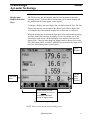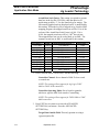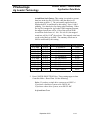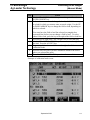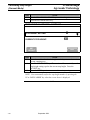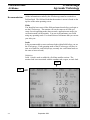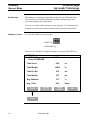
1
Precision Farming System
Operators Manual
General
PFadvantage
Ag Leader Technology
Welcome
Welcome to the Ag Leader Technology family. Ag Leader Technology is
dedicated to the development of advanced, yet practical and cost-effective
tools for grain production. Above all, however, we are dedicated to meeting
your needs for support of existing products and development of product
improvements.
We want to hear from you! Feel free to call any time to discuss:
• Operational problems with your system
• Features you don’t like about your system
• Features you would like added to your system
We will do our best to ensure that you are happy with your current system
and that it is upgraded in the future to better meet your needs.
System Upgrades
Ag Leader Technology will periodically provide operating program
upgrades that will improve the performance of your PFadvantage.
PFadvantage operating program upgrades will be available as Internet
downloadable files from the Ag Leader web site.
Internet http://www.agleader.com
If you do not have access to the Ag Leader web site contact your Ag
Leader dealer to request the latest operating program upgrades or
contact our Technical Support Group (515) 232-5363 ext. 1
Product
Registration
Your timely product registration will allow you to receive important
product bulletins and information regarding product training in your area.
Register On-Line at www.agleader.com, or return the registration form at
the front of this manual via mail or fax to the address listed below.
Ag Leader Technology
2202 South Riverside Drive
P.O. Box 2348
Ames, Iowa 50010
515-232-3595 - fax
September 2003
1-1
General
PFadvantage
Ag Leader Technology
Limited Warranty
Ag Leader Technology will repair or replace at no charge any component of the
PFadvantage system that fails during normal service on the equipment model that the
system was intended for use within two years from the warranty start date.
The warranty start date will initially be set to the date on which your product is
shipped from Ag Leader Technology.
If you return the registration/warranty card included with this manual within 30
days of purchasing this product from your dealer, the warranty start date will be
changed to the date that you purchased this product from your dealer. Ag Leader
Technology reserves the right to request proof of the date stated on your
registration/warranty card.
Warranty is not provided for damage resulting from abuse, neglect, accidents, vandalism,
acts of nature, or any other causes that are outside the normal, intended use of the
PFadvantage system.
Ag Leader Technology shall not be liable for indirect, incidental, or consequential
damages to the dealer, end user, or third parties arising from the sale, installation, or use of
the PFadvantage system.
Service
If you have a problem with your system, call your Ag Leader Technology dealer
or call us directly at the phone number below. If we determine you have a
hardware failure, we will ship replacement hardware immediately. Our mailing
address and phone numbers are:
Ag Leader Technology
2202 South Riverside Drive
P.O. Box 2348
Ames, IA 50010
Phone: 515-232-5363
Fax: 515-232-3595
Note: Return failed hardware to us by UPS (preferred) or US mail.
Copyright Notice
Ag Leader Technology has copyrighted (©2002) the contents of this manual and
the operating program for the PFadvantage system. No reproductions of this
material may be made without first obtaining the consent of Ag Leader
Technology.
Proprietary
Technology Notice
The PFadvantage system has patents on its design and operational features.
Copying features of this system relating to measurement and calculation of grain
flow and weight, or organization of field and load data may result in patent
infringement.
1-2
September 2003
General
PFadvantage
Ag Leader Technology
General
Description
The PFadvantage is a universal monitor/controller for crop production. It
can be transferred from a combine to a tractor or other vehicles easily. In
the combine it functions as a yield monitor and accurately measures and
records acres, moisture, grain weight, bushels, and yield on-the-go. In the
tractor or sprayer it connects to a sprayer or planter controller and monitors
and controls the application rate. The PFadvantage also can record data for
field boundaries, tile lines or where a hybrid is planted.
The PFadvantage has its own internal memory for recording field and load
data. GPS data, however, is not recorded in the internal memory, but
must be logged to a memory card.
The PFadvantage must be setup and calibrated to record accurate
information.
NOTE: The Grass Seed version of the PFadvantage is setup and
calibrated using the same procedures as for grain harvest. Where
there are differences between the harvest of grain verses grass seed
they will be noted.
Fields and Loads
All the information recorded by the PFadvantage must be recorded in a
field and load. The operator must manually select or change the field and
load on the PFadvantage during field operation. A load is used to
subdivide a field into smaller sections. The monitor load is not associated
with the combine tank, wagon, or truck load. It is recommended to use
different loads for different hybrids or varieties or field conditions.
Keypad
The monitor has “soft” keys which do not have labels on the keys to
identify the function of the key. The labels for the keys will appear on the
display screen next to the key. However, there are four major groups of the
keys: arrow keys, display selection keys, menu key, menu selection keys.
September 2003
1-3
General
PFadvantage
Ag Leader Technology
Display
Selection
Keys
Memory Card Slot
(On side of
PFadvantage)
Power
Switch
Arrow
Keys
Menu
Key
Area
Count
Switch
Menu
Selection
Keys
Figure 1: Front panel of the PFadvantage
Arrow Keys
The UP, DOWN, LEFT and RIGHT ARROW keys on the right side of the
keypad are used to select and change a setting. The bottom LEFT and
RIGHT ARROW keys are only used to view more menu or display items.
They are never used to select or change a setting.
On the main operating screen, you will see an up and down arrow symbol
that will either be beside the field or load or to the right of one of the
display lines. This symbol indicates what item the UP or DOWN ARROW
keys will change if pressed.
1-4
September 2003
General
PFadvantage
Ag Leader Technology
Display and
Display Selection
Keys
The PFadvantage has four display lines for viewing items on the main
operating screen. You can choose which items you see on the display and
the position that the items appear on the display.
To change a display item on a display line you must select the line. The four
display selection keys to the right of the display each select a display line.
A rectangular box surrounds the display line to show that it is selected.
When the display line is selected the four menu items on the bottom change
and show items you can select for display. Press a key below one of the
four display items to put a different display item in place of the selected
display item. There are more than four display items to choose for viewing.
Press the bottom LEFT or RIGHT ARROW keys to scroll to the right or left
and view other display items on the bottom.
Card
Symbol
Up and
Down
Arrow
Symbol
Selection
Box
When arrows present,
press bottom arrow keys
to display additional
menu or display items
Figure 2: Main operating screen
NOTE: Grass seed is measured in pounds per acre.
September 2003
1-5
General
PFadvantage
Ag Leader Technology
When some display items (like swath) are selected, an up and down arrow
symbol will appear on the right of the display line. This indicates you can
change the setting of the item with the UP or DOWN ARROW keys. After
you have made the change you must press the key to the right of the display
line to deselect the line.
Menu Key
The MENU key switches the menus on the bottom of the display. There are
two main menus that you can view by pressing the MENU key. They are
shown below.
It is recommended to display the FIELD, LOAD, MAP, and OPTIONS
menu during normal operation of the monitor, unless you are marking and
therefore need to display marks on the bottom.
Main Menus:
Menu Selection
Keys
FIELD
LOAD
SHOW
MAP
CAL
SETUP
DIAG
OPTIONS
The name above the four menu selection keys on the bottom of the display
will change depending on what you are doing on the monitor.
The bottom RIGHT and LEFT ARROW keys are used to view additional
menu or display items. If you see a right and left arrow symbol on the
display above the bottom RIGHT and LEFT ARROW keys, this indicates
you can press the bottom RIGHT and LEFT ARROW keys to view more
menu or display items. Refer to Figure 2.
1-6
September 2003
General
PFadvantage
Ag Leader Technology
Area Count Switch The area count switch manually turns on and off area counting. When the
switch is in the up position area is counting. When the switch is in the
down position, area is not counting. The monitor will display either
“AREA ON” or “AREA OFF” on the bottom right corner of the display to
indicate the status of area counting.
Connectors
The PFadvantage has six connectors on the back of the console. The large
25-pin connector is for power and sensor connections. The AUX 1 port is
for connecting to a GPS receiver. The three 9-pin RS-232 ports (Port 1, Port
2, Port 3) are for connecting to planter or fertilizer or sprayer controller or
any other GPS compatible device. The AUX 2 port is for additional
input/output signals.
AUX Port 2
AUX Port 1
(GPS)
Port 3
Port 2
Port 1
25-Pin
Connector
Figure 3 Rear of PFadvantage
September 2003
1-7
General
PFadvantage
Ag Leader Technology
Grain Flow Sensor
Below is an example of a grain flow sensor. Your grain flow sensor may
look different, depending on which combine model you have. On all
combines, the grain flow sensor installs on top of the clean grain elevator.
The grain flow sensor measures the grain weight in pounds as you harvest.
The clean grain paddles throw the grain, as the paddles rotate around the top
sprocket, toward the grain flow sensor. The flow sensor measures the grain
weight when the grain strikes the flow sensor impact plate.
NOTE: The flow sensor for grass seed harvest functions in the same
manner as the grain flow sensor. The grass seed flow sensor differs
only in appearance.
Grain Flow
Sensor
Figure 4: Grain flow sensor
1-8
September 2003
General
PFadvantage
Ag Leader Technology
Moisture Sensor
Below is an example of the moisture sensor mounted on the side of a clean
grain elevator. The moisture sensor is installed in the elevator mount kit.
Moisture Sensor
Elevator
Mount Kit
Figure 5: Moisture sensor
September 2003
1-9
General
PFadvantage
Ag Leader Technology
Header Height
Sensor
Below is an example of a header height sensor installed underneath a
combine cab. The header height sensor tells the monitor the position of the
combine head so that when the head is raised on the end rows, the monitor
stops counting area.
Header Sensor
Figure 6: Header height sensor
***
1-10
September 2003
Setup Overview
PFadvantage
Ag Leader Technology
Important Notices
The PFadvantage must be set up before field operation, but before you
begin the setup procedures, read the following notices:
The PFadvantage is a software upgradeable monitor. Ag Leader
Technology will periodically offer free operating program upgrades to
increase the capabilities of the PFadvantage. Operating program upgrades
will be available as Internet downloadable files from the Ag Leader web
site.
Internet http://www.agleader.com
If you do not have access to the Ag Leader web site, contact your Ag
Leader dealer to request the latest operating program upgrades, or contact
our Technical Support Group (515) 232-5363 ext. 1
If you plan to make yield maps on your own computer, you will need to use
a mapping program that can process files created by the PFadvantage, such
as Ag Leader’s SMS Basic mapping program. SMS Basic is available from
on CD-ROM from your Ag Leader dealer.
Section Contents
This setup section contains instructions for the following items. The
operating modes that the instructions pertain to are also listed.
Item
Console Setup
Card Setup
Creating, Naming Fields and Loads
Marker Setup
GPS Setup
Vehicle Setup
Grain Setup
Swath Setup
Swath Setup
Vehicle
Controller Setup
Raven Controller ( with Serial Ports)
Mid-Tech Controller
DICKEY-john Land Manager
DICKEY-john Seed Manager
Rawson Accu-Rate/Accu-Plant
September 2003
Operating Mode
All
All
All
All
All
Harvest
Harvest
Harvest
Site Verification
Site Verification
Application Rate
Application Rate
Application Rate
Application Rate
Application Rate
Application Rate
Page
2-6
2-8
2-12
2-17
2-19
2-30
2-34
2-39
2-41
2-42
2-42
2-44
2-49
2-55
2-61
2-65
2-1
Setup Overview
PFadvantage
Ag Leader Technology
Item
New Leader Mark III/Mark IV
Flexicoil Flexcontrol
Hiniker 8605
Teejet 844
Flowmeter Controller
Direct Drive Controller for Rawson
Accu-Rate model controllers
Using Power
Supply
2-2
Operating Mode
Application Rate
Application Rate
Application Rate
Application Rate
Application Rate
Application Rate
Page
2-73
2-79
2-85
2-91
2-95
2-100
The PFadvantage console does not need to be in the vehicle to set it up.
You can use the provided power supply (plugs into 120v outlet) to power
up the console inside your home or shop.
September 2003
Setup Overview
All Modes
PFadvantage
Ag Leader Technology
Order of Keys
(Harvest Mode)
Press the MENU key
the display.
SUMMARY
until you see the following keys on
CAL
SETUP
DIAG
Press the SETUP key to view the
following setup menu items.
SETUP
OPTIONS
PRESS
TO EXIT
SWATH
MARKS
GRAIN
CARD
LOAD
VEHICLE
CONSOLE
MEMORY
GPS
MAP
Press the bottom LEFT or RIGHT ARROW keys to
switch between and view the setup menu items
shown above.
September 2003
2-3
Setup Overview
All Modes
Order of Keys
(Site Verification
Mode)
PFadvantage
Ag Leader Technology
Press MENU key
the display.
CAL
Until you see the following keys on the
SETUP
DIAG
Press the SETUP key to view
the following setup menu items.
SETUP
OPTIONS
PRESS
TO EXIT
SWATH
MARKS
CARD
LOAD
VEHICLE
CONSOLE
MEMORY
GPS
MAP
Press the bottom LEFT or RIGHT ARROW keys to
switch between and view the setup menu items
shown above.
2-4
September 2003
Setup Overview
All Modes
PFadvantage
Ag Leader Technology
Order of Keys
(Application Rate
Mode)
Press the MENU key
the display.
CAL
until you see on the following keys on
SETUP
DIAG
Press the SETUP key to view the
following setup menu items.
SETUP
OPTIONS
PRESS
TO EXIT
APP.RATE
CONFIG
MARKS
CARD
LOAD
CONSOLE
MEMORY
GPS
MAP
Press the bottom LEFT or RIGHT ARROW keys to
switch between and view the setup menu items
shown above.
***
September 2003
2-5
Console Setup
All Modes
PFadvantage
Ag Leader Technology
Introduction
The console settings are general settings that apply to all operating modes
and uses of the PFadvantage.
Console Setup
Screen
To view the console setup screen press the:
MENU key
SETUP key
bottom RIGHT ARROW key
CONSOLE key
Example of console setup screen:
CONSOLE SETUP
Operating Mode
Month/Day/Year
Time
Serial Number
Box Cal
Voltage Cal
GPS Check Sum
Field Marker Input
Display brightness
EDIT
EXIT
ACCEPT
Changing a Setting
Step
1
2
3
2-6
GRAIN HARVEST
11/01/2002
1:15 PM
2002180001
770
490
ON
INTERNAL
80%
CANCEL
Action
Use the UP or DOWN ARROW keys to select the item you want
to change. The item is selected when a black filled rectangular
box surrounds the entire line.
Press the EDIT key and then use the UP or DOWN ARROW keys
to change the number or setting.
Once you have changed a setting press the ACCEPT key. Press
the EXIT key once you have made all the settings.
September 2003
Console Setup
All Modes
PFadvantage
Ag Leader Technology
Operating mode
The PFadvantage has the following operating modes: Grain Harvest, Grass
Seed Harvest, Cotton Harvest, HarvestMaster™, Application Rate and Site
Verification. Upon changing the operating mode you should make sure all
setup items for that operating mode are correct.
To switch modes, you must install that modes operating firmware. The
exception is Site Verification Mode. Site Verification is available with all
other modes. See "Updating Operating Program" instructions in the
Operation Section of this manual to load different firmware. All firmware
versions are on the CD that that came with the monitor or on the web at
www.agleader.com.
Units of Measure
Month/Day/Year
Time
Serial number,
Box calibration,
Voltage calibration
GPS Check Sum
Field Marker
Adjust Display
Brightness
The PFadvantage can display information in either Imperial or Metric units
of measure.
Set to the current date and time. These numbers should be set correctly
from the factory.
The serial number, box calibration number and voltage calibration number
can be found on the bottom side of the monitor. These numbers should be
set correctly from the factory.
GPS Check Sum setting is used to enable or disable data string error
checking. Normally set to ON.
If you are...
Marking field points with the PFadvantage’s
internal marker selection keys.
Marking field points with an external Ag Leader
Field Marker.
Select
INTERNAL
EXTERNAL
To adjust the display back lighting, scroll down to "Display brightness" and
press EDIT key. Use the UP or DOWN ARROW keys to adjust the screen
brightness and press the ACCEPT key.
***
September 2003
2-7
Card Setup
All Modes
Introduction
PFadvantage
Ag Leader Technology
If you are using a GPS receiver, all the GPS data must be logged to a
memory card. If you are not using a GPS receiver, you do not need a card.
The memory card must be formatted with a DOS format. Ag Leader cards
rarely need to be formatted since they are usually DOS formatted before
they are shipped. If formatting is required, format the card in your PC
before using.
IMPORTANT:
Data must be copied to each log file before you read the card into your
computer. The monitor automatically copy copies data to the card
upon shutdown.
Card Setup Screen To view the card setup screen press the:
MENU key
SETUP key
CARD key
Example of card setup screens:
CARD SETUP
Logging Device
Logging Interval
Log file
MEMORY CARD
2 second
02110101.YLD
COPY TO
CARD
EDIT
SHOW ALL
FILES
ACCEPT
CANCEL
FILES ON CARD
FILE NAME
02081502.YLD
02081501.YLD
02073001.YLD
FILE
OPTIONS
2-8
EXIT
SIZE
250 KB
128 KB
236 KB
ERASE
ALL
September 2003
LAST MODIFIED
08/15/2002
08/15/2002
07/30/2002
EXIT
Card Setup
All Modes
PFadvantage
Ag Leader Technology
FILES OPTIONS
File Name
File Size
Last Modified
Date
COPY TO
FILE
Changing a Setting
Step
1
2
3
Logging Device
02081501.YLD
132640 bytes
13:42
08/15/2002
RESTORE
FILE
ERASE
FILE
EXIT
Action
Use the UP or DOWN ARROW keys to select the item you want
to change. The item is selected when a black filled rectangular
box surrounds the entire line.
Press the EDIT key and then use the UP or DOWN ARROW keys
to change the number or setting.
Once you have changed a setting press the ACCEPT key. Press
the EXIT key once you have made all the settings.
If you are using the GPS receiver with the PFadvantage you must use a
memory card to save the instantaneous GPS data.
If you...
Select
Do not have a GPS receiver.
NONE
Do have a GPS receiver.
MEMORY CARD
NOTE: In Application Rate mode, if the PFadvantage is controlling
application rate, but you don’t want to log actual rate to card set to NONE.
Logging Interval
This setting determines how often the GPS information is saved to the
memory card. It also affects how large an area each GPS record will
represent on a map and how many logging hours are available before the
memory card becomes full.
There are three possible settings for the logging interval.
1, 2 or 3 Seconds. The recommended setting is either two or three seconds.
Distance Traveled (ft)
1 sec
2 sec
3 sec
4.4
8.8
13.2
3 mph
7.3
14.6
21.9
5 mph
September 2003
2-9
Card Setup
All Modes
PFadvantage
Ag Leader Technology
Ag Leader 32MB ATA
Flash Card
Logging Hours Available/Logging Interval
1 sec
2 sec
3 sec
400
800
1200
NOTE: The logging hours available can vary from the numbers shown above
due to the number of separate files that can be stored on the card.
Log File
The PFadvantage requires a log file to store data on a memory card. Harvest,
Site Verification and Application rate mode log files will have a “.yld”
extension. All log files will be named with the date the file was created.
Example: 02081502.yld, second file created on 08/15/2002.
IMPORTANT: Data must be copied to each log file before you read the
card into your computer. The monitor automatically copy copies data to
the card upon shutdown.
Using the Ag Leader ATA FLASH card a new log file must be created for
each day. You can not add to an old log file after a new file has been created
but you can store multiple log files on one card.
In order to log instantaneous GPS data or copy field and load data to a
memory card, a log file must be selected. Every time you turn on the
monitor, the monitor will prompt you to select or create a log file. Refer to
the steps below to select or create a log file after the monitor has been turned
on.
Step
1
2
3
Action
Select Log File and press the EDIT key.
Select a log file or press CREATE FILE key to create a new log file.
With the desired file selected, press the ACCEPT key.
NOTE: After you read all the log files on your card into your computer (and
make backup copies of files), it is recommended to erase the log file(s) on the
card.
2-10
September 2003
Card Setup
All Modes
PFadvantage
Ag Leader Technology
Copying Data to
Log File
To copy memory to log files that are not set as the current log file, press the
SHOW FILES key and select one of the log files. Press the FILE OPTIONS
key and press the COPY TO FILE key. At the card setup screen, press the
COPY TO CARD key to copy memory to the file set as the log file (this is the
same copy to card function that automatically occurs when monitor is shut
off).
Restoring from
File
You can restore field and load data into the monitor’s memory from a log file
on a memory card.
IMPORTANT: It is dangerous to restore memory from a card because
the current data in the monitor will be replaced with the data on card.
Step
1
2
3
Erasing File
Action
Press the SHOW ALL FILES key. Select the log file and press the
FILE OPTIONS key. Press the RESTORE FILE key.
Press the RESTORE key again if you really want to restore the data.
Press the EXIT key once you are finished.
You can erase individual log files from a memory card
Step
1
2
3
Action
Press the SHOW ALL FILES key. Select the log file and press the
FILE OPTIONS key. Press ERASE FILE key.
Press the ERASE key again if you really want to erase the file.
Press the EXIT key once you are finished.
IMPORTANT: Pressing ERASE ALL will erase every file from the
memory card, including non-Ag Leader files.
***
September 2003
2-11
Creating, Naming Fields, Loads
All Modes except App Rate
Recommendations
PFadvantage
Ag Leader Technology
NOTE: If using Application Rate Mode, refer to the Controller
Setup instructions on how to create and change fields. Refer to this
section for how to name fields and loads.
All the information recorded by the PFadvantage must be recorded in a
field and load. The field and load that the monitor is set on is located on the
top line of the display on the main operating screen.
Fields
It is recommended that you create all the fields and name them before you
begin to use the PFadvantage. The monitor will use the same set of fields
you create for each operating mode (harvest mode, application rate mode,
site verification) of the monitor. You can create and name your fields using
any operating mode. You should choose field names that you can use year
after year.
Loads
You may decide to create, and name loads within fields before you use the
PFadvantage however, additional loads may be created and named as
needed during field operations. Each operating mode of the PFadvantage
will have its own set of loads for each field.
Definition:
Load: A load is used to subdivide a field into smaller sections. The
monitor load is not associated with the combine tank, wagon, or
truck load.
Load
Field
2-12
September 2003
Creating, Naming Fields, Loads
All Modes except App Rate
PFadvantage
Ag Leader Technology
Creating and
Naming Fields
Step
1
Action
Press the MENU key
until the following is displayed on
the bottom of the display.
FIELD
2
SHOW
MAP
LOAD
OPTIONS
Press the FIELD key twice to view the screen below.
F1:
DG
ACTIVE FIELD
F1:
PRESS
TO EDIT NAME
SELECT GRAIN
SOYBEANS
ACCEPT
Step
3
4
CANCEL
Action
Naming Field
With the line displaying the field number selected (rectangular box
surrounds line), press the RIGHT ARROW key to move the cursor to
the right to enter a name. Use the UP or DOWN ARROW keys to scroll
through letters, numbers and other characters. After you have set the
character, move the cursor to the right by pressing the RIGHT ARROW
key and set a new character. You can enter up to an 8-character name.
Press the ACCEPT key once you have entered a name.
Setting Grain (harvest mode) or Site Type (Site Verification Mode)
To set the grain or site type for the field you must select the line
displaying the grain or site type. Press the key to the right of the line
displaying the grain or sit type to select the line. Use the UP or DOWN
ARROW keys to set the setting. Press the ACCEPT key twice, once to
accept the grain or site type, once to accept the field.
September 2003
2-13
Creating, Naming Fields, Loads
All Modes except App Rate
Step
5
6
PFadvantage
Ag Leader Technology
Action
Creating Fields
Press the UP ARROW key to scroll through all the fields. Once you
scroll past the last field, “Create New Field” will be displayed. Name
the field and set the grain or site type, then with “Create New Field”
displayed above the field number press the ACCEPT key to create the
new field.
Repeat Step 5 and create and name all your fields.
NOTE: You can have more than one grain or site type in a field.
To enter more than one grain or site type, press the FIELD key twice so that
the field is displayed in large text. Select the line displaying grain or site type
and change the setting. Press the ACCEPT key twice, once to accept the new
grain or site type and once to accept the field. The monitor will create a
separate set of loads (which are renumbered beginning with load one) for each
grain or site type in a field.
Example of load organization when two grain types are in one field in
harvest mode:
Corn
Soybeans
F10
L1
F10
L1
L2
L2
L3
L3
Site Verification types
Harvest grain types
Grass Seed types
PLANTING 1
SOYBEANS
ANNUAL RYE
PLANTING 2
PERENNIAL RYE
CORN
PLANTING 3
WHEAT
FESCUE
SPRAYING 1
ORCHARD GRASS
OATS
SPRAYING 2
CRIMSON CLOVER
RYE
SPRAYING 3
MEADOW FOAM
BARLEY
FERTILIZER 1
WHITE CLOVER
SORGHUM
BENT GRASS
POPCORN
FERTILIZER 2
FERTILIZER 3
EDIBLE BEANS
OPT SITE 1
CORN 2
OPT SITE 2
CANOLA
OPT SITE 3
RICE
OPT SITE 4
SUNFLOWERS
OPT SITE 5
CORN 3
OPT SITE 6
CORN 4
OPT GRAIN 1
OPT SITE 7
2-14
September 2003
Creating, Naming Fields, Loads
All Modes except App Rate
PFadvantage
Ag Leader Technology
Creating and
Naming Loads
Step
1
Action
Press the MENU key
until the following is displayed on
the bottom of the display.
SHOW
OPTIONS
MAP
Press the LOAD key twice to view the screen below.
FIELD
2
LOAD
F1:
L1:
DG
ACTIVE LOAD
L1:
PRESS
TO EDIT NAME
SELECT GRAIN
SOYBEANS
ACCEPT
Step
3
CANCEL
Action
Naming Load
With the line displaying the load number selected (rectangular box
surrounds line), press the RIGHT ARROW key to move the cursor to
the right to enter a name. Use the UP or DOWN ARROW keys to
scroll through letters, numbers and other characters. After you have
set the character, move the cursor to the right by pressing the RIGHT
ARROW key and set a new character. You can enter up to an 8character name. Press the ACCEPT key once you have entered a
name.
September 2003
2-15
Creating, Naming Fields, Loads
All Modes except App Rate
Step
4
5
PFadvantage
Ag Leader Technology
Action
Creating Loads
Press the UP ARROW key to scroll through all the loads in the field
for the grain type. Once you scroll past the last load, “Create New
Load” will be displayed above the load number and name. Name
the load for the displayed grain/site type, then with “Create New
Load” displayed above the load number press the ACCEPT key to
create the new load.
Repeat step 4 and create and name all your loads.
Note: Refer to Load Setup to change grain, product or site type for an
existing load.
Changing Fields
and Loads
Changing Field
Press the FIELD key to display current field. Press the UP or DOWN
ARROW keys to scroll through the fields. Press the ACCEPT key to
change to the different field.
Changing Load
Press the LOAD key to display the current load. Press the UP or DOWN
ARROW keys to scroll through the loads. Press the ACCEPT key to
change to the different load.
***
2-16
September 2003
Marker Setup
All Modes
PFadvantage
Ag Leader Technology
Introduction
If you are using an external Field Marker ignore the instructions below.
The marker setup screen is only used for making settings for the Internal
marker selection keys.
IMPORTANT:
If you are using the external field marker, make sure that under the
CONSOLE key you set Field Marker to EXTERNAL.
Marker Setup
Screen
To view the marker setup screen press the:
MENU key
SETUP key
OPTIONS key
MARKS key
Example of marker setup screen:
MARKER SETUP
MARK
NAME
TYPE
MARK 1
WEEDS
CONTINUOUS
MARK 2
ROCKS
SPOT
MARK 3
TILE
CONTINUOUS
MARK 4
WET SPOT
SPOT
EDIT
NAME
EDIT
TYPE
ACCEPT
September 2003
EXIT
CANCEL
2-17
Marker Setup
All Modes
Changing a Setting
PFadvantage
Ag Leader Technology
Step
1
2
3
4
Action
Use the UP or DOWN ARROW keys to select the mark. The
mark is selected when a black filled rectangular box surrounds the
entire line.
Press the EDIT NAME key to rename an existing mark. Use the
UP or DOWN ARROW keys to change a character in the name.
Use the LEFT or RIGHT ARROW keys to move the cursor over
another character within the name. Press the ACCEPT key after
you have changed the name.
Press the EDIT TYPE key to set the mark for continuous or spot
marking. Use the UP or DOWN ARROW keys to change the
setting. Press the ACCEPT key after you have changed the
setting.
Press the EXIT key once you have made all the settings.
Continuous marking
Set the marking type to continuous if the item in the field you are marking
requires you to make several marks in a row (for example: marking large
weed patches or tile lines).
When you press a mark key that is set for continuous marking, the mark
will remain on until you press the mark key again to turn off the mark.
Spot marking
Set the marking type to spot if the item in the field you are marking requires
just one mark (for example: marking a rock or tile hole).
When you press a mark key that is set for spot marking, the mark will
remain on only for a few seconds and then will automatically go off.
***
2-18
September 2003
GPS Setup
All Modes
PFadvantage
Ag Leader Technology
Introduction
The GPS 4100 and GPS 1000 require no initial setup to begin fieldwork.
The PFadvantage will display a “D” or “G” on the top right hand corner
of the display to indicate a GPS signal. A “D” indicates that you have a
differential signal. A “G” indicates that you have a GPS signal and you
GPS receiver are tracking four or more satellites. A lower case “g”
indicates that you have a GPS signal but your GPS receiver is tracking
only three satellites. Your GPS receiver must track four or more
satellites to get an elevation reading. You may wish to use the GPS to
show your ground speed, which requires changing the ground speed
sensor settings. Refer to Primary and Secondary Speed Sensor under
Vehicle Setup in the PFadvantage Operator’s manual for instructions.
The following provides information to change factory settings on the
GPS 4100 using the PFadvantage interface (changing GPS 1000 setting
requires the use of the GPS 1000 Utilities desktop software program.)
General
Information
Wide Area Augmentation System (WAAS) differential correction is an
alternative to subscription based satellite differential correction.
IMPORTANT: WAAS is currently free of charge, and is
being funded by the Federal Aviation Administration (FAA).
WAAS is currently in test mode, and Ag Leader Technology
can not guarantee the availability or quality of its position
signals. Only two (2) WAAS satellites are currently covering
North America.
The following provides information to change factory settings on the
GPS 4100.
WAAS Selection
If you are going to use the WAAS option complete the following:
Step
Action
1
Press Menu key on PFadvantage until SETUP is displayed,
press SETUP key.
Press bottom left or right arrow key until GPS is displayed and
press GPS key. You should now see the screen shown in
Figure 3.
2
September 2003
2-19
GPS Setup
(All Modes)
PFadvantage
Ag Leader Technology
GPS SETUP
NMEA MESSAGE
GPS INPUT/OUTPUT
BEACON DIFFERNTIAL
SATELLITE DIFFERENTIAL
LIGHTBAR
GUIDANCE
EDIT
EXIT
Figure 3. GPS SETUP Screen
Step
3
Action
At the GPS SETUP screen (Figure 3) scroll down to Satellite
Differential Mode with down arrow key and press EDIT. You
should now see the screen shown in Figure 4.
SATELLITE DIFFERENTIAL SETUP
Differential Source
WAAS
Differential Provider
Satellite Frequency
0000.0000
Satellite Baud Rate
0000
Provider User Code
0
OMNISTAR Code 000000000000000000000000
Subscription Expiration
00/00/0000
EDIT
Step
4
5
2-20
EXIT
Figure 4. Satellite Differential Setup Screen
Action
At the SATELLITE DIFFERENTIAL SETUP screen (Figure
4) Differential Source will be highlighted, press EDIT key and
use UP or DOWN ARROW key until WAAS is displayed and
press ACCEPT key.
Now press EXIT key to return to GPS SETUP screen, press
EXIT key again to return to the main operating screen.
September 2003
GPS Setup
All Modes
PFadvantage
Ag Leader Technology
Satellite Selection
If you will be using the satellite differential option then do the following
depending on which service provider you select.
Step
1
Action
Press Menu key on PFadvantage until SETUP is
displayed, press SETUP key.
Press bottom left or right arrow key until GPS is
displayed and press GPS key.
At the GPS SETUP screen scroll down to Satellite
Differential with down arrow key and press EDIT.
2
3
GPS SETUP
NMEA MESSAGE
GPS INPUT/OUTPUT
BEACON DIFFERNTIAL
SATELLITE DIFFERENTIAL
LIGHTBAR
GUIDANCE
EDIT
EXIT
September 2003
2-21
GPS Setup
(All Modes)
PFadvantage
Ag Leader Technology
SATELLITE DIFFERENTIAL SETUP
Differential Source
Satellite
Differential Provider
Omnistar
Satellite Frequency
0000.0000
Satellite Baud Rate
0000
Provider User Code
0
OMNISTAR Code 00000000000000000000000000
ACCEPT
If you will
be using…
Omnistar
2-22
CANCEL
Then…
At SATELLITE DIFFERENTIAL SETUP screen
Differential Source will be highlighted, press EDIT key
and use up or down arrow key until Satellite is displayed
and press ACCEPT key. Scroll down to Differential
Provider and press EDIT key. Use the UP or DOWN
ARROW key until Omnistar is displayed and press
ACCEPT key. Scroll down to Satellite Frequency and
press EDIT key. Use the UP or DOWN ARROW key to
select your region and press ACCEPT key. If you will be
using a custom frequency with this provider, scroll down
to Custom (1) and push EDIT NAME key. Use the UP or
DOWN and LEFT or RIGHT ARROW keys to name this
frequency. Push EDIT VALUE key and use the UP or
DOWN and LEFT or RIGHT ARROW keys to enter the
frequency. Push ACCEPT key. Your customized
frequency should appear as the Satellite Frequency.
September 2003
GPS Setup
All Modes
PFadvantage
Ag Leader Technology
SATELLITE DIFFERENTIAL SETUP
Oministar Satellite Beacon Frequencies:
Eastern USA
1556.825
Central USA
1554.497
Western USA (1)
1551.429
Western USA (2)
1551.489
Australia
1558.510
Europe
1531.230
South America (1)
1541.705
South America (2)
1541.715
Custom (1)
0000.0
Custom (2)
0000.0
ACCEPT
September 2003
CANCEL
2-23
GPS Setup
All Modes
PFadvantage
Ag Leader Technology
SATELLITE DIFFERENTIAL SETUP
Oministar Satellite Beacon Frequencies:
Eastern USA
1556.825
Central USA
1554.497
Western USA (1)
1551.429
Western USA (2)
1551.489
Australia
1558.510
Europe
1531.230
South America (1)
1541.705
South America (1)
1541.705
Custom (1)
0000.0
Custom (2)
0000.0
EDIT
NAME
ACCEPT
If you will
be using…
Omnistar
2-24
EDIT
VALUE
CANCEL
Then…
Call the Omnistar subscription number (713-785-5850 in
the USA) and give them the number to the right of the GPS
serial number. Omnistar will then give you a 24-digit
code. Key the code into the right of Omnistar Code using
UP and DOWN ARROW keys. Once the code is entered,
press ACCEPT key to send the code to the unit. Now
press EXIT key to return to GPS SETUP screen, press
EXIT key to return to operating screen. After 30 minutes,
the receiver should start receiving corrections and display a
“D” in the upper right hand corner of the PFadvantage.
September 2003
GPS Setup
All Modes
PFadvantage
Ag Leader Technology
SATELLITE DIFFERENTIAL SETUP
Differential Source
Satellite
Differential Provider
RACAL
Satellite Frequency
1553.345000
Satellite Baud Rate
1200
Provider User Code
8111
OMNISTAR Code 00000000000000000000000000
ACCEPT
If you will
be using …
THALES
(RACAL)
CANCEL
Then…
At SATELLITE DIFFERENTIAL SETUP screen
Differential Source will be highlighted press EDIT key
and use UP or DOWN ARROW key until Satellite is
displayed and press ACCEPT key. Scroll down to
Differential Provider and press EDIT key. Use the UP
or DOWN ARROW key until RACAL is displayed and
press ACCEPT key. Scroll down to Satellite Frequency
and press EDIT key. Use the UP or DOWN ARROW
key to select your region and press ACCEPT key. If
you will be using a custom frequency with this provider,
scroll down to Custom (1) and push EDIT NAME key.
Use the UP or DOWN and LEFT or RIGHT ARROW
keys to name this frequency. Push EDIT VALUE key
and use the UP or DOWN and LEFT or RIGHT
ARROW keys to enter the frequency. Push ACCEPT
key. Your customized frequency should appear as the
Satellite Frequency.
September 2003
2-25
GPS Setup
All Modes
PFadvantage
Ag Leader Technology
SATELLITE DIFFERENTIAL SETUP
RACAL Satellite Beacon Frequencies:
North American East
1553.345
North American Mntn
1554.350
North American West
1556.225
Australia
1558.525
Europe
1531.210
South Africa
1552.640
Custom (1)
0000.0
Custom (2)
0000.0
Custom (3)
0000.0
Custom (4)
0000.0
ACCEPT
CANCEL
SATELLITE DIFFERENTIAL SETUP
RACAL Satellite Beacon Frequencies:
North American East
1553.345
North American Mntn
1554.350
North American West
1556.225
Australia
1558.525
Europe
1531.210
South Africa
1552.640
Custom (1)
0000.0
Custom (2)
0000.0
Custom (3)
0000.0
Custom (4)
0000.0
EDIT
NAME
ACCEPT
If you will
be using …
THALES
(RACAL)
2-26
EDIT
VALUE
CANCEL
Then…
Call the THALES (RACAL) subscription number (713-7844482 in the USA) and give them the number to the right of the
GPS serial number. THALES (RACAL) will activate a code
for the serial number that was given. After the serial number
is called in, press the EXIT key to return to operating screen.
Within 15 to 30 minutes the receiver should start receiving
corrections from THALES (RACAL). A “D” should appear in
the upper right hand corner of the PFadvantage.
September 2003
GPS Setup
All Modes
PFadvantage
Ag Leader Technology
SATELLITE DIFFERENTIAL SETUP
Differential Source
Satellite
Differential Provider
RACAL
Satellite Frequency
1553.345000
Satellite Baud Rate
1200
Provider User Code
8111
OMNISTAR Code 00000000000000000000000000
ACCEPT
Beacon Selection
CANCEL
The settings for beacon selection are Auto range, Auto Power and Manual.
• Auto Range: This is the default setting. In this setting the receiver keeps
a record of the closest three beacons within the receivers range. It then
selects a beacon based on the ranking of the beacon in memory.
• Auto Power: The receiver keeps a record of the three strongest beacons in
its range. It then selects a beacon based on the ranking of the available
beacons.
• Manual: Allows you to input frequencies for two beacons.
To change Beacon Selection complete the following steps:
Step
1
2
Action
Press Menu key on PFadvantage until SETUP is displayed
and press SETUP.
Press bottom left or right arrow key until GPS is displayed
and press GPS key.
September 2003
2-27
GPS Setup
All Modes
PFadvantage
Ag Leader Technology
GPS SETUP
NMEA MESSAGE
GPS INPUT/OUTPUT
BEACON DIFFERNTIAL
SATELLITE DIFFERNTIAL
LIGHTBAR
GUIDANCE
EDIT
Step
3
4
EXIT
Action
From the GPS SETUP screen scroll down to BEACON
DIFFERNTIAL and press EDIT key. Use up or down
arrow keys to set mode.
After setting Auto Power mode, push ACCEPT key and
then EXIT.
BEACON SETUP
Mode:
Channel 0 Frequency
Channel 1 Frequency
ACCEPT
2-28
Auto Power
AUTO
AUTO
EXIT
September 2003
GPS Setup
All Modes
PFadvantage
Ag Leader Technology
BEACON SETUP
Mode:
Channel 0 Frequency
Channel 1 Frequency
Manual
300.0
300.0
ACCEPT
Step
5
6
EXIT
Action
If you are setting to Manual push ACCEPT key then use
down arrow key to scroll to Channel 0 Frequency and
press EDIT key. Use the up or down arrow key to set
desired frequency and press ACCEPT key. Scroll down
to Channel 1 Frequency and press EDIT key. Use up or
down arrow keys to set desired frequency and press
ACCEPT key.
Press the EXIT key two times to return to operating
screen.
***
September 2003
2-29
Vehicle Setup
Harvest Mode
PFadvantage
Ag Leader Technology
Introduction
For each operating mode, there are different items to setup in the vehicle
setting screen. Below are the setup items for the harvest mode. Refer to
your Initial Calibration Sheet to make the correct settings.
Vehicle Setup
Screen
To view the vehicle setup screen press the:
MENU key
SETUP key
bottom RIGHT ARROW key
VEHICLE key
Example of vehicle setup screen:
VEHICLE SETUP
Elevator pulses / revolution
Sprocket teeth
Combine scale factor
Area count stop beeps
Expand grain below dry %
Sensor calibration
T1
T2
T3
Primary speed sensor
Secondary speed sensor
Speed sensor pulses / 100 ft
2-30
1 Pulses
8 Teeth
1.0
20 Beeps
NO
1400
10
5
8
WHEELS
--------2000 Pulses
EDIT
EXIT
ACCEPT
CANCEL
September 2003
Vehicle Setup
Harvest Mode
PFadvantage
Ag Leader Technology
Step
1
Changing a Setting
2
3
Action
Use the UP or DOWN ARROW keys to select the item you want
to change. The item is selected when a black filled rectangular
box surrounds the entire line.
Press the EDIT key and then use the UP or DOWN ARROW keys
to change the number or setting.
Once you have changed a setting press the ACCEPT key. Press
the EXIT key once you have made all the settings.
Elevator
pulses/revolution
Refer to the Initial Calibration Sheet for the correct setting for your
combine.
Sprocket teeth
Refer to the Initial Calibration Sheet for the correct setting for your
combine.
Combine scale
factor
Refer to the Initial Calibration Sheet for the correct setting for your
combine.
IMPORTANT:
• Never change the scale factor during harvest. Doing so will cause
the monitor to lose calibration accuracy and you will have to set the
monitor on different grain types and recalibrate every grain type.
•
All of your calibration loads and data loads must be harvested using
the same scale factor setting otherwise you will have severe
calibration problems that possibly can not be corrected.
September 2003
2-31
Vehicle Setup
Harvest Mode
Area count stop
beeps
PFadvantage
Ag Leader Technology
This setting is for the number of times the monitor beeps when the head is
raised at the end of a pass and the monitor stops counting area.
NOTE: The recommended setting is 20. Set this number high enough so
that after the head is raised at the end of a pass, the beeps continue until the
combine is completely turned around and the head is lowered to start the
new pass. This gives the operator an audible signal that the head is
lowered enough to begin counting area again.
Expand grain below If you select . . .
No,
Dry %
Yes,
Then . . .
You prevent the monitor from adding bushels to grain
that is dryer than the dry percent moisture by which dry
bushels are calculated. This calculates all yields in terms
of actual bushels available for you to sell.
(Recommended setting).
The monitor shows a yield comparison of all loads at
the dry percent moisture. This increases the bushels of
the grain harvested below the dry percent moisture to
account for moisture lost because of excessive dryness
of the grain.
NOTE: This setting applies to all loads and grains in the monitor. It can be
changed from NO to YES and vice-versa at any time.
Sensor calibration
Refer to the Initial Calibration Sheet for the correct setting for your
combine.
NOTE: If you replace the flow sensor, you must change this setting to the
value of the new sensor calibration number for the new flow sensor. The
sensor calibration number is listed on the flow sensor serial number tag.
T1, T2, T3
2-32
Refer to the Initial Calibration Sheet for the correct setting for your
combine.
September 2003
Vehicle Setup
Harvest Mode
PFadvantage
Ag Leader Technology
Primary and
Secondary speed
sensor
The monitor has four different primary speed settings. They are listed
below.
Ground Speed Sensor
Speed sensor on transmission
Speed sensor on tracks
Radar gun
GPS receiver
Primary Speed Sensor
WHEEL
TRACK
RADAR
GPS
If you choose GPS as your primary speed sensor, you need to set the
secondary speed sensor to WHEEL, TRACK, or RADAR. If the GPS
signal is lost, the monitor will use the secondary speed sensor. If you do
not choose GPS as your primary speed sensor you can not set the secondary
speed sensor.
Speed sensor pulses
/ 100 ft.
It is not recommended that you change this setting. This number is the
distance calibration number that is set when you perform a distance
calibration for WHEEL, TRACK or RADAR. Refer to the calibrating
distance instructions in the Calibration section. You must calibrate distance
for a WHEEL, TRACK or RADAR setting for accurate ground speed.
NOTE: If you want to use a radar gun, contact an Ag Leader Technology
dealer and purchase a special adapter cable for your radar gun.
***
September 2003
2-33
Grain Setup
Harvest Mode
PFadvantage
Ag Leader Technology
NOTE: Grass Seed monitors are setup using the same
procedures as Grain.
Grain Setup
To view the grain setup screen press the:
Screen
MENU key
SETUP key
GRAIN key
Example of grain setup screen:
GRAIN SETUP
GRAIN
NAME
GRAIN 1
SOYBEANS
GRAIN 2
CORN
Hi Flow
GRAIN 3
WHEAT
Low Flow
GRAIN 4
OATS
Low Flow
EDIT
NAME
EDIT
SETTINGS
ACCEPT
2-34
TYPE
Low Flow
EXIT
CANCEL
September 2003
Grain Setup
Harvest Mode
PFadvantage
Ag Leader Technology
Changing a Setting
Step
1
2
3
4
Action
Use the UP or DOWN ARROW keys to select the grain. The
grain is selected when a black filled rectangular box surrounds the
entire line.
Press the EDIT SETTINGS key to move to another screen and
change the settings for the selected grain. Refer to the screen
below.
Press the EDIT NAME key to rename an existing grain (can not
rename SOYBEANS, CORN, or WHEAT). Use the UP or
DOWN ARROW keys to change a character in the name. Use the
LEFT or RIGHT ARROW keys to move the cursor over another
character within the name. Once you have changed the grain
name press the ACCEPT key.
Press the EXIT key once you have made all the settings.
Example of grain settings screen:
GRAIN SETTINGS: CORN
Dry lbs / bu
Dry moisture
Moisture offset
Stop height
M1
S1
56 lb / bu
13.0 %
4.7 %
54
400
50
EDIT
EXIT
ACCEPT
CANCEL
September 2003
2-35
Grain Setup
Harvest Mode
PFadvantage
Ag Leader Technology
Dry lbs / bu
This setting is the pounds / bushel value that the monitor uses to calculate
bushels. You can change this setting for all grains except corn (56 lbs / bu),
soybeans (60 lbs / bu) and wheat (60 lbs / bu).
Dry moisture
This setting is the moisture value that the monitor uses to calculate dry
bushels.
Example:
Corn – 15%
Soybeans – 13%
Scale Factor
For grass seed the recommended setting is 1. Settings are 1, 10, 100.
Moisture offset
Refer to the Initial Calibration Sheet for the correct setting. Do not readjust
the moisture offset number after you have performed a moisture calibration.
Stop Height
This setting determines how high the combine head must be raised to make
the monitor stop counting area. This number can be automatically set under
the CAL, STOP HGT key.
M1
Refer to the Initial Calibration Sheet for the correct setting.
S1
Refer to the Initial Calibration Sheet for the correct setting.
Setting Initial C
Numbers
The 11 C Numbers, C1 through C11 determine the pounds of grain that the
monitor calculates. The C numbers initially should be set to the same
values that appear on your Initial Calibration Sheet, but they will change
and become more accurate after you have calibrated.
Do not change the C numbers after you have calibrated.
You only need to set the C11 number to its initial value. When you set the
C11 number, the C2-C10 numbers will automatically change to the correct
value. Do not set the C1 number. It is adjusted automatically when you do
a vibration calibration.
2-36
September 2003
Grain Setup
Harvest Mode
PFadvantage
Ag Leader Technology
Changing C11
Step
1
Action
You must display the weight calibration screen.
Press the following keys to view the weight calibration screen:
MENU key
CAL key
WEIGHT key
2
3
4
5
6
Refer to the screens on the next page and press the UP or DOWN
ARROW keys to set a grain type that you will harvest. Press the
SHOW CAL NUMBERS key.
Use the DOWN ARROW key to select C11 number (a line is
selected when the entire line is surrounded by a black filled box).
Press the EDIT key. Use the UP or DOWN ARROW keys to set
the correct number according to the Initial Calibration Sheet.
Press the ACCEPT key.
Press the EXIT key once to return to the previous screen. Repeat
steps 2-4 and set C11 for all the grain types you will harvest.
Press the EXIT key twice to return to the main operating screen.
NOTE: You may not be able to set C11 to the exact number that is on the
Initial Calibration Sheet. C2-C10 numbers also may not exactly agree
with the Initial Calibration Sheet. If this is the case, set C11 as close to the
initial number as possible.
September 2003
2-37
Grain Setup
Harvest Mode
PFadvantage
Ag Leader Technology
GRAIN CALIBRATION
SELECT GRAIN:
SOYBEANS
ENTER
WEIGHT
SHOW CAL
LOADS
SHOW CAL
NUMBERS
EXIT
GRAIN CALIBRATION: SOYBEANS
CALIBRATION NUMBERS
C1
C2
C3
C4
C5
C6
C7
C8
C9
C10
C11
EDIT
0
250
500
750
1000
1250
1500
1750
2000
2250
2500
CAL
ON/OFF
PERFORM
CAL
ACCEPT
CANCEL
***
2-38
EXIT
September 2003
Swath Setup
Harvest Mode
PFadvantage
Ag Leader Technology
Introduction
The swath setup screen is used to set the permanent, full swath of your
head. Do not adjust the swath setting on this screen when you encounter a
partial swath while harvesting. Refer to the Swath Setting instructions in
Operation Section and select swath as a display item and set a partial swath.
Swath Setup
Screen
To view the swath setup screen press the:
MENU key
SETUP key
SWATH key
Example of swath setup screen:
SWATH SETUP
GRAIN
# ROWS
SPACING
FULL SWATH
SOYBEANS
24
12 in
CORN
8
30 in
20 ft 0 in
WHEAT
24
12 in
24 ft 0 in
OATS
24
12 in
24 ft 0 in
EDIT
# ROWS
EDIT
SPACING
ACCEPT
24 ft 0 in
EXIT
CANCEL
September 2003
2-39
Swath Setup
Harvest Mode
PFadvantage
Ag Leader Technology
Changing a Setting
Step
1
2
3
4
Action
Use the UP or DOWN ARROW keys to select the grain. The
grain is selected when a black filled rectangular box surrounds the
entire line.
Press the EDIT # ROWS key to change the number of rows. Use
the UP or DOWN ARROW keys to change the number. Press the
ACCEPT key after you have changed the number.
Press the EDIT SPACING key to change the row spacing. Use the
UP or DOWN ARROW keys to change the number. Press the
ACCEPT key after you have changed the number.
Press the EXIT key once you have made all the settings.
Recommendations for Row Crop Heads:
• For row crops, set your row space to the planted row spacing and your
number of rows to the number of total rows of your combine head.
Recommendations for Cutting Platform Heads:
Row Crops
• For row crops, set your row space to the planted row spacing and your
number of rows to the number of total rows your cutting platform will
cut.
Non-rowed crops
• Set the swath in the monitor to one foot less than the actual swath width
of the head because you can rarely maintain a constant full swath while
harvesting.
Example: If your cutting platform head is 20 actual feet, set the
monitor’s swath to 19 feet by setting the row space to 12 inches and the
number of rows to 19.
•
Set the monitor on a row space of 12 inches and a number of rows that
adds up to the correct swath. Setting the row space to 12 inches for
cutting platforms allows you to reduce the cutting swath by easier-to-see
one-foot increments when you are harvesting a partial swath
Refer to the Swath Setting instructions in the Operation Section for more
information about partial swath.
***
2-40
September 2003
Swath Setup
Site Verification Mode
PFadvantage
Ag Leader Technology
Introduction
The swath setup screen is used to set the permanent, full swath of your
application equipment. Do not adjust the swath setting on this screen when
you encounter a partial swath in the field. Refer to the Swath Setting
instructions in Operation Section and select swath as a display item and set
a partial swath.
NOTE: If you do not want to count area, you do not need to set the
swath.
Swath Setup
Screen
Refer to the swath setup instructions for harvest mode for instructions on
viewing the swath setup screen and setting the swath.
Recommendations
To enter a swath setting, you must enter a number of rows setting and a row
spacing setting for the product you are applying.
Application equipment that uses row units
If your application equipment is applying the product with row units, then
enter the number of rows and row spacing of the application equipment.
Application equipment that uses boom sections
If your application equipment is applying the product using boom sections
enter the width of the boom section in inches for the row spacing setting.
Enter the total number of booms for the number of rows setting. If your
boom sections are not all the same width, enter twelve inches for the row
spacing setting and a number rows setting that makes the total swath equal
the full swath of the application equipment.
Application equipment that uses a spreader mechanism
If your application equipment is applying the product using a spreading
mechanism enter twelve inches for the row spacing setting and a number
rows setting that makes the total swath equal the full swath of the
application equipment.
***
September 2003
2-41
Vehicle Setup
Site Verification Mode
PFadvantage
Ag Leader Technology
Introduction
For each operating mode, there are different items to setup in the vehicle
setting screen. Below are the setup items for the site verification mode.
Vehicle Setup
Screen
To view the vehicle setup screen, press the MENU key, SETUP key and
VEHICLE key to view the following:
VEHICLE SETUP
TRACTOR
TRUCK
ATV
OPTIONAL 1
OPTIONAL 2
OPTIONAL 3
OPTIONAL 4
ACCEPT
VEHICLE
EDIT
NAME
EDIT
SETTINGS
CANCEL
Use the UP or DOWN ARROW key select a vehicle type. Press EDIT
NAME key. Use the UP or DOWN ARROW key to name the vehicle type
and press SAVE NAME key.
To edit vehicle settings press EDIT SETTINGS key to view the following:
VEHICLE SETUP
Primary speed sensor
Secondary speed sensor
Speed sensor pulses / 100 ft
Area count stop beeps
Area Count
Stop height
2-42
WHEELS
--------2000 Pulses
20 Beeps
STANDARD
8
EDIT
EXIT
ACCEPT
CANCEL
September 2003
Vehicle Setup
Site Verification Mode
PFadvantage
Ag Leader Technology
Press the UP or DOWN ARROW key to scroll down to highlight a setting
and press the EDIT key to change a setting, then press ACCEPT key. After
making changes, press EXIT key.
Choose the vehicle you want to use and press ACCEPT VEHICLE key.
Area count stop
beeps
This setting is for the number of times the monitor beeps when the monitor
stops counting area at the end of a pass.
Primary and
Secondary speed
sensor
The monitor has four different primary speed settings. They are listed
below.
Ground Speed Sensor
Speed sensor on transmission
Speed sensor on tracks
Radar gun
GPS receiver
Primary Speed Sensor
WHEEL
TRACK
RADAR
GPS
***
September 2003
2-43
Raven Controller (with Serial Port)
Application Rate Mode
PFadvantage
Ag Leader Technology
NOTE: If your Raven console has a serial port, it
will be on the back of the console. It is a nine-pin
rectangular computer port. The Raven 750 and
760 serial port is built-in the main wiring harness.
Not all Ravens consoles have a serial port.
Cable attachment
for Raven
controllers with
serial ports
PFadvantage
Port 3
Raven Serial Cable (p.n. 2000944)
ATV Battery Power Cable
(p.n. 2000497-2)
Raven Console
Cable attachment from Raven console to monitor
The Raven Serial Cable enables the PFadvantage to control the rate. It
also provides swath width (based on the number of booms on), actual
rate and area count status (based on Master Switch) information to the
PF.
Setup for Raven
controllers with
serial ports
Complete the following steps to set up for Raven – Sidekick, 440, 450,
460, 660, 700, 710, 750, 760 controllers with serial ports.
A separate configuration of settings should be created for every product
applied. A maximum of 16 different configurations can be created. The
screen below illustrates two configurations set up for a Raven 440.
1. Press SETUP key. Press APP RATE CONFIG key. A screen
similar to the one below should appear.
2-44
September 2003
Raven Controller (with Serial Port)
Application Rate Mode
PFadvantage
Ag Leader Technology
APP RATE CONFIG
PRODUCT
CONTROLLER
Treflan
440
Roundup
440
EDIT
SETTINGS
CREATE
NEW
DELETE
CHANNEL
Rate 1
Rate 1
EXIT
Press CREATE NEW key to set up a new configuration or
select an existing configuration and press the EDIT
SETTINGS key. A new screen appears with the following
settings. Select each setting and press EDIT key to change the
settings.
Controller Make: Set to RAVEN. This setting can not be
changed once the configuration is used by one or more fields.
Controller Model: Set to the Raven model you have. For
example: 440 or 460 etc. This setting can not be changed once
the configuration is used by one or more fields.
Product: Press EDIT key. You can select an existing product
and press ACCEPT key or create a new product by pressing
CREATE NEW key. Press EDIT NAME key and enter name
of product. Use Left or Right Arrow keys to select a character.
Use Up or Down Arrow key to change the character. To erase
a character in the name, highlight that character and use UP or
DOWN ARROW key to scroll to the blank space between "9"
and "A". Set every character and press ACCEPT key twice.
Units: Usually set to GALLONS. Set to Units/Acre of
application.
Ground Speed Sensor: Set primary speed sensor to GPS.
SERIAL is not recommended. RADAR is an option but you
will need additional cabling to connect the radar to your
monitor. All Ag Leader GPS except GPS 1000 will work for
ground speed.
Note: This setting affects all configurations.
September 2003
2-45
Raven Controller (with Serial Port)
Application Rate Mode
PFadvantage
Ag Leader Technology
App Distance From GPS: Set to distance between where
product exits applicator and position of GPS antenna on
vehicle. Example: If spray boom is 20 feet behind GPS
antenna set to 20 feet back. Press DOWN ARROW key to set
feet back, UP ARROW key to set feet forward.
Full Swath: Ignore setting. Swath automatically comes from
serial port of Raven. The swath on the PF automatically
changes as boom sections are turned ON or OFF.
Tgt Units: Contrler Units: Normally set to 1:1.0000. This
ratio is used to convert the units in a target file (.tgt) to the
units of application.
Example: Tgt file in pints/ac of Treflan, Raven applies based
on gallons/ac. If tank mix is 1 pint of Treflan / 10 gallon
water, then set to 1:10.0000. The PFadvantage will read the
pints/acre rate out of the tgt file, multiply it by ten to convert
it to gallons/ac and send that rate to the Raven console as the
rate to be applied.
Target Rate Increment: Determines increment value by
which you can change the manual target rate with each press
of Up or Down arrow keys. Choices are 0.1, 1.0, 10.0, 100.0,
500.0, 1000.0, 5000.0 or 10000.0.
Actual Rate Scale Factor: This setting is required to prevent
data loss in the log file (YLD file) when the units/sec of
application get above 3. Use the chart below for setting. The
rate actually applied and rate displayed on PFadvantage is
unaffected by this setting. When the log file is mapped in Ag
Leader's SMS mapping program, the mapped actual rate will
be 1/10th of the real rate if the Actual Rate Scale Factor is
0.100. If it is 0.010, the mapped actual rate will be 1/100th the
real rate. The mapped actual rate can be scaled back up in
SMS. The summary actual rate in SMS is unaffected by this
setting.
2-46
September 2003
Raven Controller (with Serial Port)
PFadvantage
Application Rate Mode
Ag Leader Technology
Avg. Speed
0-25 mph
0-10 mph
11-15 mph
11-15 mph
16-25 mph
0-25 mph
0-10 mph
11-15 mph
11-15 mph
16-25 mph
0-25 mph
Swath
Application Rate between
0-80 ft
0-10 units/ac
0-80 ft
11-100 units/ac
0-50 ft
11-100 units/ac
51-80 ft
11-100 units/ac
0-80 ft
11-100 units/ac
0-80 ft
101-500 units/ac
0-80 ft
501-1000 units/ac
0-50 ft
501-1000 units/ac
51-80 ft
501-1000 units/ac
0-80 ft
501-1000 units/ac
0-80 ft
1001+ units/ac
Scale Factor
1.000
1.000
1.000
0.100
0.100
0.100
0.100
0.100
0.010
0.010
0.010
2. If you have a 440, 450, or 460 ignore this step, otherwise press
CONTRLER SETTINGS key. Set the following:
Controller Channel: Set to channel of Raven to record or
control rate.
Controller Operating Mode: Set to liquid or granular,
whichever type the Raven console is controlling.
3. Press EXIT key to return to screen with ADVANCED
SETTINGS key on bottom. Press the ADVANCED
SETTINGS key.
Target Rate Outside Field: This only pertains to using a
.tgt prescription file.
Set to ZERO if want rate outside field to be zero.
Set to USE LAST if want rate to be the last rate used at
the time the vehicle is detected outside the field. This is
useful when the vehicle is being falsely detected outside
of the field during the outside pass.
Set to TGT DEFAULT if want rate outside field to be the
default rate stored in the .tgt prescription file.
Controller Time Delay: Set to 3 seconds. This is delay of
controller to change application equipment to new rate + 2
seconds.
September 2003
2-47
Raven Controller (with Serial Port)
Application Rate Mode
PFadvantage
Ag Leader Technology
Actual Rate Units: Ignore this setting.
Log Actual Rate: Set to YES to log actual rate to card.
Set to No, otherwise.
4. This completes all the settings for one configuration. Press
EXIT key twice to return to screen showing all configurations
or press EXIT key 3 times and menu key to return to main
operating system.
Activating
Configuration and
Setting .tgt
Prescription File
5. Exit back to main screen.
a) Press FIELD key twice.
b) Select appropriate field and press VIEW CONFIG key.
c) Select appropriate product/controller configuration and
press ACTIVE ON/OFF key to check it as active. (All
other configurations must be unchecked first).
d) If you will be using a .tgt prescription file. Press EDIT
TGT FILE key, otherwise press EXIT key and skip to
step f.
e) Select .tgt file. Press VIEW INFO key to ensure it is
the correct one. After exiting view info screen, press
ACCEPT key. Press EXIT key.
f) Press ACCEPT key to accept field.
Settings for Raven.
Under Data Menu key, set Baud = 9600, Trig = 1, Unit = sec,
Dlog = ON. To turn the rate change alarm OFF set Rate = OFF.
On some Ravens the Dlog setting has to be reset when the
console is turned ON.
Additional
Instructions
For more information on setting Target Rate, display items,
creating and using .tgt prescription files and logging actual rate see
the Operation Section in this manual.
2-48
September 2003
PFadvantage
Mid-Tech Controller
Ag Leader Technology
Application Rate Mode
Cable attachment
for Mid-Tech
controllers that
are connected to
Data-Link
consoles
PFadvantage
Port 3
ATV Battery
Power Cable
(p.n. 2000497-2)
Data-Link
Cable attachment from Mid-Tech console to monitor
The Mid-Tech Data-Link console provides a serial cable connection
between the PF and Ag Logix or the TASC controller. The serial cable
enables the PFadvantage to control and record the rate. It also provides
swath width (based on the number of booms on), ground speed, actual
rate and area count status (based on Master Switch) information to the
PFadvantage.
September 2003
2-49
Mid-Tech Controller
PFadvantage
Application Rate Mode
Ag Leader Technology
Setup for MidTech controllers
that are
connected to
Data-Link
consoles
Complete the following steps to set up for Ag Logic, TASC 6000,
6100, 6200, 6300, 6500, 6600 with Data Link.
A separate configuration of settings should be created for every
product applied. A maximum of 16 different configurations can be
created. The screen below illustrates two configurations set up for a
Mid-Tech.
1. Press SETUP key. Press APP RATE CONFIG key. A screen
similar to the one below should appear.
APP RATE CONFIG
PRODUCT
CONTROLLER
Treflan
TASC 6100
Roundup
TASC 6100
EDIT
SETTINGS
CREATE
NEW
DELETE
CHANNEL
Carrier
Carrier
EXIT
Press CREATE NEW key to set up a new configuration or select
an existing configuration and press the EDIT SETTINGS key. A
new screen appears with the following settings. Select each
setting and press EDIT key to change the settings.
Controller Make: Set to MIDTECH. This setting can not be
changed once the configuration is used by one or more fields.
Controller Model: Set to the MIDTECH model you have. For
example: TASC 6100 etc. This setting can not be changed once
the configuration is used by one or more fields.
Product: Press EDIT key. You can select an existing product
and press ACCEPT key or create a new product by pressing
CREATE NEW key. Press EDIT NAME key and enter name of
product. Use Left or Right Arrow keys to select a character. Use
Up or Down Arrow key to change the character. To erase a
character in the name, highlight that character and use UP or
DOWN ARROW key to scroll to the blank space between "9"
and "A". Set every character and press ACCEPT key twice.
2-50
September 2003
PFadvantage
Mid-Tech Controller
Ag Leader Technology
Application Rate Mode
Units: Set to Units/Acre of application. Set to
GALLONS if applying liquid. Set to POUNDS if
applying granular product.
Ground Speed Sensor: Set primary speed sensor to
SERIAL. The monitor will get ground speed from the
serial cable connection to the Mid-Tech. Leave the
secondary speed sensor set to WHEEL and do not change
the Speed Sensor Pulses/100 ft. Also do not perform a
distance calibration using wheel selection. No calibration
is needed when primary speed is set to SERIAL.
Note: This setting affects all configurations.
App Distance From GPS: Set to distance between where
product exits applicator and position of GPS antenna on
vehicle. Example: If spray boom is 20 feet behind GPS
antenna set to 20 feet back. Press DOWN ARROW key to
set feet back, UP ARROW key to set feet forward.
Full Swath: Ignore setting. Swath automatically comes
from serial port of Mid-Tech. The swath on the PF
automatically changes as boom sections are turned ON or
OFF.
Tgt Units: Contrler Units: This only pertains to using a
.tgt prescription file. Normally set to 1:1.0000. This ratio
is used to convert the units in a target file (.tgt) to the units
of application.
Example: Tgt file in pints/ac of Treflan, Mid-Tech
applies based on gallons/ac. If tank mix is 1 pint
of Treflan / 10 gallon water, then set to 1:10.0000.
The PF will read the pints/acre rate out of the .tgt
file, multiply it by ten to convert it to gallons/ac
and send that rate to the Mid-Tech console as the
rate to be applied.
Target Rate Increment: Determines increment value by
which you can change the manual target rate with each
press of Up or Down arrow keys. Choices are 0.1, 1.0,
10.0, 100.0, 500.0, 1000.0, 5000.0 or 10000.0.
September 2003
2-51
Mid-Tech Controller
PFadvantage
Application Rate Mode
Ag Leader Technology
Actual Rate Scale Factor: This setting is required to prevent
data loss in the log file (YLD file) when the units/sec of
application get above 3. Use the chart below for setting. The
rate actually applied and rate displayed on PF is unaffected by
this setting. When the log file is mapped in Ag Leader's SMS
mapping program, the mapped actual rate will be 1/10th of the
real rate if the Actual Rate Scale Factor is 0.100. If it is
0.010, the mapped actual rate will be 1/100th the real rate.
The mapped actual rate can be scaled back up in SMS. The
summary actual rate in SMS is unaffected by this setting.
Avg. Speed
0-25 mph
0-10 mph
11-15 mph
11-15 mph
16-25 mph
0-25 mph
0-10 mph
11-15 mph
11-15 mph
16-25 mph
0-25 mph
Swath
Application Rate between
0-80 ft
0-80 ft
0-50 ft
51-80 ft
0-80 ft
0-80 ft
0-80 ft
0-50 ft
51-80 ft
0-80 ft
0-80 ft
Scale Factor
0-10 units/ac
11-100 units/ac
11-100 units/ac
11-100 units/ac
11-100 units/ac
101-500 units/ac
501-1000 units/ac
501-1000 units/ac
501-1000 units/ac
501-1000 units/ac
1001+ units/ac
1.000
1.000
1.000
0.100
0.100
0.100
0.100
0.100
0.010
0.010
0.010
2. Press CONTRLER SETTINGS key. Set the following:
Controller Channel: Set to channel of Mid-Tech to record
or control rate.
NOTE: This setting will not appear for Ag Logix, TASC
6000 or TASC 6100 controllers.
Controller Operating Mode: Set to liquid or granular,
whichever type the Mid-Tech console is controlling.
NOTE: This setting will not appear for TASC 6000 or TASC
6600 controllers.
3. Press EXIT key to return to screen with ADVANCED
SETTINGS key on bottom. Press the ADVANCED
SETTINGS key.
Target Rate Outside Field: This only pertains to using a
.tgt prescription file.
2-52
September 2003
PFadvantage
Mid-Tech Controller
Ag Leader Technology
Application Rate Mode
Set to ZERO if want rate outside field to be zero.
Set to USE LAST if want rate to be the last rate used at
the time the vehicle is detected outside the field. This is
useful when the vehicle is being falsely detected outside
of the field during the outside pass.
Set to TGT DEFAULT if want rate outside field to be the
default rate stored in the .tgt prescription file.
Controller Time Delay: Set to 3 seconds. This is delay of
controller to change application equipment to new rate + 2
seconds.
Actual Rate Units: Ignore this setting.
Log Actual Rate: Set to YES to log actual rate to card. Set
to No, otherwise.
This completes all the settings for one configuration. Press
EXIT key twice to return to screen showing all
configurations or press EXIT key 3 times and menu key to
return to main operating system.
September 2003
2-53
Mid-Tech Controller
PFadvantage
Application Rate Mode
Ag Leader Technology
Activating
Configuration and
Setting .tgt
Prescription File
4. Exit back to main screen.
a) Press FIELD key twice.
b) Select appropriate field and press VIEW CONFIG key.
c) Select appropriate product/controller configuration and
press ACTIVE ON/OFF key to check it as active. (All
other configs must be unchecked first).
d) If you will be using a .tgt prescription file. Press EDIT
TGT FILE key, otherwise press EXIT key and skip to
step f.
e) Select .tgt file. Press VIEW INFO key to ensure it is
the correct one. After exiting view info screen, press
ACCEPT key. Press EXIT key.
f) Press ACCEPT key to accept field.
Settings on DataLink
Move the switch to "External Enable" position. The lights on the
Data-Link will flash back and forth when communication is
established with the PF. The Channel switch on Mid-Tech, must
be in the "Alt-Rate" position for PF to send target rate to
controller. If you do not want PF to control target rate, but want it
to record the actual rate from a channel, set the channel switch on
Mid-Tech to "ON" or "Standard" (exception: on Ag Logix, PF can
not receive actual rate without controlling target rate).
Additional
Instructions
For more information on setting Target Rate, display items,
creating and using .tgt prescription files and logging actual rate see
the Operation Section in this manual.
2-54
September 2003
DICKEY-john Land Manager
PFadvantage
Application Rate Mode
Ag Leader Technology
Cable attachment
for DICKEY-john
Land Manager or
Land Manager II
controller
PFadvantage
Port 3
Dickey-john Serial Cable (p.n. 2000991)
ATV Battery
Power Cable
(p.n. 2000497-2)
Land Manager
Cable attachment for DICKEY-john Land Manager console
The DICKEY-john Serial Cable enables the PFadvantage to control and
record the rate. It also provides swath width (based on the number of
booms on), ground speed, actual rate and area count status (based on
Master Switch) information to the PFadvantage.
September 2003
2-55
DICKEY-john Land Manager
PFadvantage
Application Rate Mode
Setup for a
DICKEY-john
Land Manager or
Land Manager II
controller
Ag Leader Technology
Complete the following steps to set up for Land Manager or Land
Manager II controllers.
A separate configuration of settings should be created for every
product applied. A maximum of 16 different configurations can
be created. The screen below illustrates two configurations set up
for a DICKEY-john.
1. Press SETUP key. Press APP RATE CONFIG key. A screen
similar to the one below should appear.
APP RATE CONFIG
PRODUCT
Treflan
Roundup
EDIT
SETTINGS
CONTROLLER
Land Manager
Land Manager
CREATE
NEW
DELETE
CHANNEL
NA
NA
EXIT
Press CREATE NEW key to set up a new configuration or select
an existing configuration and press the EDIT SETTINGS key.
A new screen appears with the following settings. Select each
setting and press EDIT key to change the settings.
Controller Make: Set to DICKEY-JOHN. This setting can not
be changed once the configuration is used by one or more fields.
Controller Model: Set to LAND MANAGER. This setting can
not be changed once the configuration is used by one or more
fields.
2-56
September 2003
DICKEY-john Land Manager
PFadvantage
Application Rate Mode
Ag Leader Technology
Product: Press EDIT key. You can select an existing
product and press ACCEPT key or create a new product
by pressing CREATE NEW key. Press EDIT NAME key
and enter name of product. Use Left or Right Arrow keys
to select a character. Use Up or Down Arrow key to
change the character. To erase a character in the name,
highlight that character and use UP or DOWN ARROW
key to scroll to the blank space between "9" and "A". Set
every character and press ACCEPT key twice.
Units: Set to GALLONS if applying liquid. Set to
POUNDS if applying granular product. Set to Units/Acre
of application.
Ground Speed Sensor: Set primary speed sensor to
SERIAL. The monitor will get ground speed from the
serial cable connection to the Land Manager. Leave the
secondary speed sensor set to WHEEL and do not change
the Speed Sensor Pulses/100 ft. Also do not perform a
distance calibration using wheel selection. No calibration
is needed when primary speed is set to SERIAL.
Note: This setting affects all configurations.
App Distance From GPS: Set to distance between where
product exits applicator and position of GPS antenna on
vehicle. Example: If spray boom is 20 feet behind GPS
antenna set to 20 feet back. Press DOWN ARROW key to
set feet back, UP ARROW key to set feet forward.
Full Swath: Ignore setting. Swath automatically comes
from serial port of the DICKEY-john. The swath on the
PF automatically changes as boom sections are turned ON
or OFF.
Tgt Units: Contrler Units: Normally set to 1:1.0000.
This ratio is used to convert the units in a target file (.tgt)
to the units of application.
September 2003
2-57
DICKEY-john Land Manager
PFadvantage
Application Rate Mode
Ag Leader Technology
Example: Tgt file in pints/ac of Treflan, Land Manager
applies based on gallons/ac. If tank mix is 1 pint of Treflan /
10 gallon water, then set to 1:10.0000. The PF will read the
pints/acre rate out of the .tgt file, multiply it by ten to convert
it to gallons/ac and send that rate to the Land Manager
console as the rate to be applied.
Target Rate Increment: Determines increment value by
which you can change the manual target rate with each press
of Up or Down arrow keys. Choices are 0.1, 1.0, 10.0, 100.0,
500.0, 1000.0, 5000.0 or 10000.0.
Actual Rate Scale Factor: This setting is required to prevent
data loss in the log file (YLD file) when the units/sec of
application get above 3. Use the chart below for setting. The
rate actually applied and rate displayed on PF is unaffected by
this setting. When the log file is mapped in Ag Leader's SMS
mapping program, the mapped actual rate will be 1/10th of the
real rate if the Actual Rate Scale Factor is 0.100. If it is
0.010, the mapped actual rate will be 1/100th the real rate.
The mapped actual rate can be scaled back up in SMS. The
summary actual rate in SMS is unaffected by this setting.
Avg. Speed
0-25 mph
0-10 mph
11-15 mph
11-15 mph
16-25 mph
0-25 mph
0-10 mph
11-15 mph
11-15 mph
16-25 mph
0-25 mph
Swath
Application Rate between
Scale Factor
0-80 ft
0-80 ft
0-50 ft
51-80 ft
0-80 ft
0-80 ft
0-80 ft
0-50 ft
51-80 ft
0-80 ft
0-80 ft
0-10 units/ac
11-100 units/ac
11-100 units/ac
11-100 units/ac
11-100 units/ac
101-500 units/ac
501-1000 units/ac
501-1000 units/ac
501-1000 units/ac
501-1000 units/ac
1001+ units/ac
1.000
1.000
1.000
0.100
0.100
0.100
0.100
0.100
0.010
0.010
0.010
2. Press CONTRLER SETTINGS key. Set the following:
Controller Operating Mode: Set to liquid, granular or
NH3 whichever type the Land Manager console is
controlling.
2-58
September 2003
DICKEY-john Land Manager
PFadvantage
Application Rate Mode
Ag Leader Technology
3. Press EXIT key to return to screen with ADVANCED
SETTINGS key on bottom. Press the ADVANCED
SETTINGS key.
Target Rate Outside Field: This only pertains to using a
.tgt prescription file.
Set to ZERO if want rate outside field to be zero.
Set to USE LAST if want rate to be the last rate used at
the time the vehicle is detected outside the field. This is
useful when the vehicle is being falsely detected outside
of the field during the outside pass.
Set to TGT DEFAULT if want rate outside field to be the
default rate stored in the .tgt prescription file.
Controller Time Delay: Set to 3 seconds. This is delay of
controller to change application equipment to new rate + 2
seconds.
Actual Rate Units: Ignore this setting.
Log Actual Rate: Set to YES to log actual rate to card. Set
to NO, otherwise.
This completes all the settings for one configuration. Press
EXIT key twice to return to screen showing all
configurations or press EXIT key 3 times and menu key to
return to main operating system.
September 2003
2-59
DICKEY-john Land Manager
Application Rate Mode
Activating
Configuration and
Setting .tgt
Prescription File
PFadvantage
Ag Leader Technology
4. Exit back to main screen.
a) Press FIELD key twice.
b) Select appropriate field and press VIEW CONFIG key.
c) Select appropriate product/controller configuration and
press ACTIVE ON/OFF key to check it as active. (All
other configs must be unchecked first).
d) If you will be using a .tgt prescription file. Press EDIT
TGT FILE key, otherwise press EXIT key and skip to
step f.
e) Select .tgt file. Press VIEW INFO key to ensure it is
the correct one. After exiting view info screen, press
ACCEPT key. Press EXIT key.
Press ACCEPT key to accept field.
Settings on Land
Manager Console
On Land Manager console, press the SYSTEM key. Select
Configuration and press Enter. Select Serial Port and press
Enter. Verify that “Active Config” is set to GPS. If it is not, select
GPS and press Enter. Verify that the GPS selection is 9600-N-8.
If it is not, select Modify Active and set Baud Rate=9600,
Parity=None, Data Bits=8 and Connect=Direct.
Additional
Instructions
For more information on setting Target Rate, display items,
creating and using .tgt prescription files and logging actual rate see
the Operation Section in this manual.
2-60
September 2003
DICKEY-john Seed Manager
PFadvantage
Application Rate Mode
Ag Leader Technology
Cable attachment
for DICKEY-john
Seed Manager or
Vanguard VM2500 (PIC)
PFadvantage
Port 3
Dickey-john Serial Cable (p.n. 2000947)
ATV Battery
Power Cable
(p.n. 2000497-2)
Vanguard PIC or
Dickey-john Seed
Manager Console
The DICKEY-john serial cable enables the PFadvantage to record the
population rate. It also provides swath width (based on the number of
non-failed rows), ground speed, actual rate and area count status
information to the PFadvantage.
September 2003
2-61
DICKEY-john Seed Manager
PFadvantage
Application Rate Mode
Setup for
DICKEY-john
Seed Manager or
Vanguard VM2500 (PIC)
Ag Leader Technology
Complete the following steps to set up for Seed Manager or
Vanguard VM-2500 PIC planter monitor.
A separate configuration of settings should be created for every
product applied. A maximum of 16 different configurations can
be created. The screen below illustrates two configurations set up
for a DICKEY-john.
1. Press SETUP key. Press APP RATE CONFIG key. A screen
similar to the one below should appear.
APP RATE CONFIG
PRODUCT
CONTROLLER
Corn
Seed Manager
Soybeans
Seed Manager
EDIT
SETTINGS
CREATE
NEW
DELETE
CHANNEL
Channel 1
Channel 1
EXIT
Press CREATE NEW key to set up a new configuration or select
an existing configuration and press the EDIT SETTINGS key.
A new screen appears with the following settings. Select each
setting and press EDIT key to change the settings.
Controller Make: Set to DICKEY-JOHN. This setting can not
be changed once the configuration is used by one or more fields.
Controller Model: Set to SEED MANAGER. This setting can
not be changed once the configuration is used by one or more
fields.
2-62
September 2003
DICKEY-john Seed Manager
PFadvantage
Application Rate Mode
Ag Leader Technology
Product: Press EDIT key. You can select an existing
product and press ACCEPT key or create a new product
by pressing CREATE NEW key. Press EDIT NAME key
and enter name of product. Use Left or Right Arrow keys
to select a character. Use Up or Down Arrow key to
change the character. To erase a character in the name,
highlight that character and use UP or DOWN ARROW
key to scroll to the blank space between "9" and "A". Set
every character and press ACCEPT key twice.
Units: Set to SEEDS.
Ground Speed Sensor: Set primary speed sensor to
SERIAL. The monitor will get ground speed from the
serial cable connection to the Seed Manager. Leave the
secondary speed sensor set to WHEEL and do not change
the Speed Sensor Pulses/100 ft. Also do not perform a
distance calibration using wheel selection. No calibration
is needed when primary speed is set to SERIAL.
Note: This setting affects all configurations.
App Distance From GPS: Ignore setting. This setting
pertains to using a .tgt prescription file.
Full Swath: Ignore setting. Swath automatically comes
from serial port of the DICKEY-john.
Tgt Units: Contrler Units: Ignore setting. This setting
pertains to using a .tgt prescription file.
Target Rate Increment: Ignore setting.
Actual Rate Scale Factor: Set to 1.000.
September 2003
2-63
DICKEY-john Seed Manager
Application Rate Mode
Activating
Configuration
PFadvantage
Ag Leader Technology
2. Exit back to main screen.
a) Press FIELD key twice.
b) Select appropriate field and press VIEW CONFIG key.
c) Select appropriate product/controller configuration and
press ACTIVE ON/OFF key to check it as active. (All
other configs must be unchecked first).
d) Press ACCEPT key to accept field.
Settings on Seed
Manager Console
There are no settings required on the Seed Manager to establish
communication.
Additional
Instructions
For more information on setting Target Rate, display items,
creating and using .tgt prescription files and logging actual rate see
the Operation Section in this manual.
2-64
September 2003
Rawson Accu-Rate/Accu-Plant
PFadvantage
Application Rate Mode
Ag Leader Technology
Cable attachment
for Rawson AccuRate Controller
PFadvantage
Tractor Cab Cable
(p.n. 2000493)
Rawson Serial Cable
(p.n. 2000952)
(Same as PC Cable)
Port 3
Com A
Rawson Accu-Rate Console
Drive A
Connection
Drive B Connection
Rawson Accu-Rate Tee Cable
(p.n. 2000890)
Rawson Wiring Harness-Drive Speed Connection.
Rawson Wiring Harness--Power,
Ground Speed, and Area Count
Connections.
The Rawson serial cable (p.n. 2000952) enables the PFadvantage to
control the rate of the Rawson processor. The Rawson Accu-Rate Tee
Cable (p.n. 2000890) provides power, radar ground speed and actual rate
(based on drive rpm) signals to the PF.
September 2003
2-65
Rawson Accu-Rate/Accu-Plant
PFadvantage
Application Rate Mode
Ag Leader Technology
Cable attachment
for Rawson AccuRate and Seed
Manager
Rawson Serial Cable (p.n. 2000952)
(Same as PC cable)
Com A
PFadvantage
Rawson
Console
ATV Battery
Power Cable
(p.n. 2000497-2)
Port 3
Port 2
Dickey-john Serial
Cable (p.n. 2000947)
Vanguard PIC or
Dickey-john Seed
Manager Console
The diagram above shows connections required for the PF to control the
population of the Accu-Rate and record the actual population as
measured by the Seed Manager or Vanguard VM 2500 (PIC). The
ground speed, swath width and area count status come from the Seed
Manager.
2-66
September 2003
Rawson Accu-Rate/Accu-Plant
PFadvantage
Application Rate Mode
Ag Leader Technology
Cable attachment
for Rawson AccuPlant Controller
PFadvantage
Serial Cable
(p.n. 2000952)
Tractor Cab Cable
(p.n. 2000493)
Rawson Accu-Plant or New
Leader Mark III Console
Rawson Accu-Plant/Mark III
Tee Cable (p.n. 2000499)
Rawson or New Leader main wiring
harness.
Cable attachment for Rawson Accu-Plant Controller.
The Rawson serial cable (p.n. 2000952) enables the PFadvantage to
control the rate of the Rawson processor. The Rawson Accu-Plant Tee
Cable (p.n. 2000499) provides power, radar ground speed and actual rate
(based on drive rpm) signals to the PF.
September 2003
2-67
Rawson Accu-Rate/Accu-Plant
Application Rate Mode
Setup for
Rawson AccuRate or AccuPlant Controller
PFadvantage
Ag Leader Technology
Complete the following steps to setup for Rawson Accu-Rate or
Accu-Plant.
A separate configuration of settings should be created for every
product applied. A maximum of 16 different configurations can be
created. The screen below illustrates two configurations for a
Accu-Rate controller.
1. Press SETUP key. Press APP RATE CONFIG key. A screen
similar to the one below should appear:
APP RATE CONFIG
PRODUCT
CONTROLLER
Corn
ACCU-RATE
Hybrid B
ACCU-RATE
EDIT
SETTINGS
CREATE
NEW
DELETE
CHANNEL
N/A
N/A
EXIT
Press CREATE NEW key to set up a new configuration or select an
existing configuration and press the EDIT SETTINGS key. A new
screen appears with the following settings. Select each setting and
press EDIT key to change the settings.
Controller Make: Set to RAWSON.
Controller Model: Set to ACCU-RATE or ACCU-PLANT.
Product: Press EDIT key. You can select an existing product and
press ACCEPT key or create a new product by pressing CREATE
NEW key. Press EDIT NAME key and enter name of product. Use
Left or Right Arrow keys to select a character. Use Up or Down
Arrow key to change the character. To erase a character in the name,
highlight that character and use UP or DOWN ARROW key to scroll
to the blank space between "9" and "A". Set every character and
press ACCEPT key twice.
2-68
September 2003
Rawson Accu-Rate/Accu-Plant
PFadvantage
Application Rate Mode
Ag Leader Technology
Units: Set to Units/Acre of application. Set to SEEDS if planting.
Set to TONS if applying lime. Set to POUNDS if applying
fertilizer. Set to GALLONS if applying liquid.
Ground Speed Sensor: Set to RADAR or GPS. All Ag Leader
GPS except GPS 1000 will work for ground speed. If getting
actual rate from Seed Manger Planter monitor set to SERIAL.
Note: This setting affects all configurations
App Distance From GPS: Set to distance between where product
exits applicator and position of GPS antenna on vehicle. Example:
If the planter is 20 feet behid GPS antenna set to 20 feet back.
Press DOWN ARROW key to set feet back, UP ARROW key to set
feet forward.
Full Swath: Set to full swath of applicator.
Tgt Units: Contrler Units: Normally set to 1:1.0000. This ratio is
used to convert the units in a target file (.tgt) to the units of
application. Example: Tgt file in pounds/ac of lime, Rawson
applies lime in tons/ac. Set to 1:0.0005 to convert pounds/acre to
tons/ac. The PF will read the rate from the .tgt prescription file and
multiply it by 0.0005 and send that rate to the Rawson processor.
Target Rate Increment: Determines increment value by which
you can change the manual target rate with each press of Up or
Down arrow keys. Choices are 0.1, 1.0, 10.0, 100.0, 500.0, 1000.0,
5000.0 or 10000.0. Suggested setting when planting corn is 500.0
or 1000.0. For planting beans use 1000.0 or 5000.0 or 10000.0.
For applying lime use 0.1. For applying fertilizer or liquid use 1.0
or 10.0.
Actual Rate Scale Factor: Set to 1.000.
Press CONTRLER SETTINGS key. Set the following:
September 2003
2-69
Rawson Accu-Rate/Accu-Plant
Application Rate Mode
PFadvantage
Ag Leader Technology
Nominal Rate: If the PF is not controlling the rate, ignore this setting. If
the PF is controlling the rate, this setting must equal the nominal rate
setting in the Rawson processor.
Press the MODE key on the Rawson processor until the nominal rate
appears. The nominal rate should appear as follows for the different
modes of the Rawson processor.
“Sds/A=x,xxx,xxx” – Rawson plant mode
“Rate=xxxx.x Lb/A” – Rawson dry fertilizer mode
“Rate=xx.x Gal/A” – Rawson liquid fertilizer mode
Percent rate change: If the PF is not controlling the rate, ignore this
setting. If the PF is controlling the rate, this setting must equal the
“Steps” setting in the Rawson processor.
The “Steps” setting is not changeable or viewable in the Accu-Plant
processor. The settings are…
4.00% for plant mode of Accu-Plant processor
6.66% for fertilizer mode of Accu-Plant processor
The “Steps” setting is changeable in the Accu-Rate processor. Press the
MODE key on the Accu-Rate processor until “Steps x.x%” appears. The
default settings for each mode are below.
4.00% for plant mode of Accu-Rate processor
6.66% for fertilizer mode of Accu-Rate processor
Cal. number for act. rate: Use the formula below for the appropriate
mode to determine this setting.
Planting mode - Press MODE key on processor to view the “# of
seeds=xxx.x” and “No. of Rows=xx” setting.
# of seeds
x No. of rows x 10 = Cal. number for act. rate
5
Liquid fertilizer mode - Press MODE key on processor to view
“Pump Disp x.xxxx”, “RateSetting xx.x” and “Ratio=xx.xx:1”
setting.
Pump Disp x Rate Setting x 10000
= Cal. number for act. rate
Ratio
2-70
September 2003
Rawson Accu-Rate/Accu-Plant
PFadvantage
Application Rate Mode
Ag Leader Technology
Dry fertilizer mode - Press MODE key on processor to view
“Del. Rate=xxx.xx”, “Mat’l=xxx.x Lb”, “Rate Setting xx.xx”
and “Ratio=xx.xx:1” setting.
Del. Rate x Mat'l x Rate Setting x .5787
= cal. number
Ratio
NOTE: Actual rate will be 1/10th of real actual rate
(except for lime). If cal. number is over 6400, divide cal.
number by 10. Ex. 7000/10=700 (act. rate will be 1/100th
of real actual rate). If gate setting changes, switch
configurations and enter new cal. number.
Actual Rate Source: Set to DRIVE RPM. Actual Rate will be
determined based on rpm of hydraulic drive. If you are planting
and have a Dickey-john Seed Manager monitor and you want to
get the actual rate from it, set this to SEED MANGR.
2. Press EXIT key to return to screen with ADVANCED SETTINGS
key on bottom. Press the ADVANCED SETTINGS key.
Target Rate Outside Field: This only pertains to using a target
file.
Set to ZERO if want rate outside field to be zero.
Set to USE LAST if want rate to be the last rate used at the time
the vehicle is detected outside the field. This is useful when
experiencing problems with the vehicle being falsely detected
outside of the field during the outside pass.
Set to TGT DEFAULT if want rate outside field to be the default
rate stored in the target rate file.
Controller Time Delay: Set to 2 seconds. This is delay of
controller to change application equipment to new rate + 2
seconds.
Actual Rate Units: Ignore this setting.
Log Actual Rate: Set to YES to log actual rate to card. Set to
NO, otherwise.
September 2003
2-71
Rawson Accu-Rate/Accu-Plant
Application Rate Mode
PFadvantage
Ag Leader Technology
3. Exit back to main screen.
a)Press FIELD key twice.
b)Select appropriate field and press VIEW CONFIG key.
c)Select appropriate product/controller configuration and press
ACTIVE ON/OFF key to check it as active.(All other configs
must be unchecked first).
d)If you will be using a target file, press EDIT TGT FILE key,
otherwise press EXIT key and skip to step f.
e)Select target file. Press VIEW INFO key to ensure it is the
correct one. After exiting view info screen, press ACCEPT
key. Press EXIT key.
f)Press ACCEPT key to accept field.
Settings on
Rawson processor
If the PF is controlling the rate, the Rawson processor must be set to
"GPS Mode" under the mode key. Otherwise, no settings need to be
made on the Rawson processor.
Additional
Instructions
For more information on setting Target Rate, display items, creating and
using .tgt prescription files and logging actual rate see the Operation
Section in this manual.
2-72
September 2003
New Leader Controller
PFadvantage
Application Rate Mode
Ag Leader Technology
Cable attachment
for New Leader
Mark III or Mark
IV processors
PFadvantage
Rawson Serial Cable (p.n. 2000952)
New Leader Mark III Console
or
New Leader Mark IV Console
Tractor Cab Cable
(p.n. 2000493)
If Mark III processor use Tee
Cable p.n. 2000499
New Leader Mark IV main wiring harness.
If Mark IV processor use Tee
Cable p.n. 2000945
The New Leader tee cable (p.n. 2000945) provides power, radar ground
speed and actual rate (based on drive rpm) signals to the PF. The
Rawson Serial Cable (p.n. 2000952) enables the PF to control the rate of
the New Leader processor.
September 2003
2-73
New Leader Controller
PFadvantage
Application Rate Mode
Setup for New
Leader Mark III
or Mark IV
controllers
Ag Leader Technology
Complete the following steps to setup for New Leader Mark III or Mark
IV.
A separate configuration of settings should be created for every product
applied. A maximum of 16 different configurations can be created. The
screen below illustrates two configurations set up for a Mark IV.
1. Press SETUP key. Press APP RATE CONFIG key. A screen
similar to the one below should appear:
APP RATE CONFIG
PRODUCT
Lime
Fertilizer
EDIT
SETTINGS
CONTROLLER
Mark IV
Mark IV
CREATE
NEW
CHANNEL
N/A
N/A
DELETE
EXIT
Press CREATE NEW key to set up a new configuration or select an
existing configuration and press the EDIT SETTINGS key. A new
screen appears with the following settings. Select each setting and
press EDIT key to change the settings.
Controller Make: Set to NEW LEADER.
Controller Model: Set to MARK III or MARK IV
Product: Press EDIT key. You can select an existing product and
press ACCEPT key or create a new product by pressing CREATE
NEW key. Press EDIT NAME key and enter name of product. Use
Left or Right Arrow keys to select a character. Use Up or Down
Arrow key to change the character. To erase a character in the name,
highlight that character and use UP or DOWN ARROW key to scroll
to the blank space between "9" and "A". Set every character and
press ACCEPT key twice.
2-74
September 2003
New Leader Controller
PFadvantage
Application Rate Mode
Ag Leader Technology
Units: Set to Units/Acre of application. Set to TONS if applying lime.
Set to POUNDS if applying fertilizer.
Ground Speed Sensor: Set to RADAR or GPS. All Ag Leader GPS
except GPS 1000 will work for ground speed.
Note: This setting affects all configurations.
App Distance From GPS: Set to distance between where product exits
applicator and position of GPS antenna on vehicle. Example: If the
spinner is 20 feet behind GPS antenna set to 20 feet back. Press DOWN
ARROW key to set feet back, UP ARROW key to set feet forward.
Full Swath: Set to spread width of applicator.
Tgt Units: Contrler Units: Normally set to 1:1.0000. This ratio is used
to convert the units in a target file (.tgt) to the units of application.
Example: Tgt file in pounds/ac of lime, New Leader Mark processor
applies lime in tons/ac. Set to 1:0.0005 to convert pounds/acre to tons/ac.
The PF will read the rate from the .tgt prescription file and multiply it by
0.0005 and send that rate to the Mark processor.
Target Rate Increment: Determines increment value by which you can
change the manual target rate with each press of Up or Down arrow keys.
Choices are 0.1, 1.0, 10.0, 100.0, 500.0, 1000.0, 5000.0 or 10000.0.
Suggested setting for applying lime is 0.1. For applying fertilizer use 1.0
or 10.0.
Actual Rate Scale Factor: Set to 1.000 if applying lime. Set to 0.100 if
applying fertilizer. This setting is required to prevent data loss in the log
file (YLD file) when the units/sec of application get above 3. The rate
actually applied and rate displayed on PF is unaffected by this setting.
When the log file is mapped in Ag Leader SMS mapping program, the
mapped actual rate will be 1/10th of the real rate if the Actual Rate Scale
Factor is 0.100. If it is 0.010, the mapped actual rate will be 1/100th the
real rate. The mapped actual rate can be scaled back up in SMS. The
summary actual rate in SMS is unaffected by this setting.
Press CONTRLER SETTINGS key. Set the following:
September 2003
2-75
New Leader Controller
PFadvantage
Application Rate Mode
Ag Leader Technology
Nominal Rate: If the PF is not controlling the rate, ignore this
setting. If the PF is controlling the rate, this setting must equal the
nominal rate setting in the Mark processor.
Press the MODE key on the Mark processor until the nominal rate
appears. The nominal rate should appear as follows for the
different modes of the Mark processor.
"Yield = xxxx Lb/A" – Fert Mode
"Yield = xx.x T/A" – Lime Mode
Percent rate change: If the PF is not controlling the rate, ignore
this setting. If the PF is controlling the rate, this setting must
equal 6.66%.
Cal. number for act. Rate: Use the formula below to dtermine
this setting.
New Leader – Press Mode key on controller to view
“FeedGate=xx.xx”, “Mat’l=xxx.x Lb”, and “Conv. Rate=x.xxx”
settings. Use formula to determine cal. number.
Feed Gate x Mat'l x Conv. Rate x 1000 (5 if lime)
= cal. number
6.1
NOTE: When As Applied data is mapped in mapping program,
actual rate will be 1/10th of real actual rate (except for lime). If
cal. number is over 6400, divide cal. number by 10. Ex.
7000/10=700 (mapped actual rate will be 1/100th of real actual
rate). If feed gate setting changes, switch configurations and
enter new cal. number.
2. Press EXIT key to return to screen with ADVANCED SETTINGS
key on bottom. Press the ADVANCED SETTINGS key
2-76
September 2003
New Leader Controller
PFadvantage
Application Rate Mode
Ag Leader Technology
Target Rate Outside Field: This only pertains to using a target
file.
Set to ZERO if want rate outside field to be zero.
Set to USE LAST if want rate to be the last rate used at the time
the vehicle is detected outside the field. This is useful when
experiencing problems with the vehicle being falsely detected
outside of the field during the outside pass.
Set to TGT DEFAULT if want rate outside field to be the default
rate stored in the target rate file.
Controller Time Delay: Set to 2 seconds. This is delay of
controller to change application equipment to new rate + 2
seconds.
Actual Rate Units: Ignore this setting.
Log Actual Rate: Set to YES to log actual rate to card. Set to
NO, otherwise.
3. Exit back to main screen.
a)Press FIELD key twice.
b)Select appropriate field and press VIEW CONFIG key.
c)Select appropriate product/controller configuration and press
ACTIVE ON/OFF key to check it as active.(All other configs
must be unchecked first).
d)If you will be using a target file, press EDIT TGT FILE key,
otherwise press EXIT key and skip to step f.
e)Select target file. Press VIEW INFO key to ensure it is the
correct one. After exiting view info screen, press ACCEPT
key. Press EXIT key.
f)Press ACCEPT key to accept field.
September 2003
2-77
New Leader Controller
PFadvantage
Application Rate Mode
Ag Leader Technology
Settings on New
Leader processor
If the PF is controlling the rate, the New Leader processor must be set to
"GPS Mode" under the mode key. Otherwise, no settings need to be
made on the New Leader processor.
Additional
Instructions
For more information on setting Target Rate, display items,
creating and using .tgt prescription files and logging actual rate
see the Operation Section of this manual.
2-78
September 2003
PFadvantage
Flexicoil Flexcontrol
Ag Leader Technology
Application Rate Mode
Cable attachment
for Flexcontrol
controller
PFadvantage
Flexicoil Cable part number 14927SU1
ATV Battery Power Cable
(p.n. 2000497-2)
Flexcontrol
The Serial cable connecting between the PF and Flexcontrol enables the
PF to control the rate. It also provides ground speed, swath width (based
on number of boom sections on ) and actual rate information to the PF.
September 2003
2-79
Flexicoil Flexcontrol
PFadvantage
Application Rate Mode
Ag Leader Technology
Setup for
Flexcontrol
controller
A separate configuration of settings should be created for every product
applied. A maximum of 16 different configurations can be created. The
screen below illustrates two configurations set up for the Flexcontrol
controller.
1. Press SETUP key. Press APP RATE CONFIG key. A screen
similar to the one below should appear:
APP RATE CONFIG
PRODUCT
CONTROLLER
Fertilizer 1
Flexcontrol
Fertilizer 2
Flexcontrol
EDIT
SETTINGS
CREATE
NEW
CHANNEL
Air Tank 1
Air Tank 2
DELETE
EXIT
1. Press CREATE NEW key to set up a new configuration or select an
existing configuration and press the EDIT SETTINGS key. A new
screen appears with the following settings. Select each setting and
press EDIT key to change the settings.
Controller Make: Set to FLEXICOIL.
Controller Model: Set to FLEXCONTROL
Product: Press EDIT key. You can select an existing product and
press ACCEPT key or create a new product by pressing CREATE
NEW key. Press EDIT NAME key and enter name of product.
Use Left or Right Arrow keys to select a character. Use Up or
Down Arrow key to change the character. To erase a character in
the name, highlight that character and use UP or DOWN ARROW
key to scroll to the blank space between "9" and "A". Set every
character and press ACCEPT key twice.
Units: Set to Units/Acre of application. Set to POUNDS if
applying fertilizer. Set to GALLONS if applying liquid.
2-80
September 2003
PFadvantage
Flexicoil Flexcontrol
Ag Leader Technology
Application Rate Mode
Ground Speed Sensor: Set primary speed sensor to SERIAL.
The monitor will get ground speed from the serial cable
connection to the Flexcontrol. Leave the secondary speed sensor
set to WHEEL and do not change the Speed Sensor Pulses/100 ft.
Also do not perform a distance calibration using wheel selection.
No calibration is needed when primary speed is set to SERIAL.
Note: This setting affects all configurations.
App Distance From GPS: Set to distance between where product
exits applicator and position of GPS antenna on vehicle. Example:
If the boom is 20 feet behid GPS antenna set to 20 feet back. Press
DOWN ARROW key to set feet back, UP ARROW key to set feet
forward.
Full Swath: Ignore setting. Swath automatically comes from
serial port of Flexcontrol. The swath on the PF automatically
changes as boom sections are turned ON or OFF.
Tgt Units: Contrler Units: Normally set to 1:1.0000. This ratio
is used to convert the units in a .tgt prescription file to the units of
application.
Example: Tgt file in pints/ac of Treflan, Flexcontrol
applies based on gallons/ac. If tank mix is 1 pint of Treflan
/ 10 gallon water, then set to 1:10.0000. The PF will read
the pints/acre rate out of the .tgt file, multiply it by ten to
convert it to gallons/ac and send that rate to the
Flexcontrol console as the rate to be applied.
Target Rate Increment: Determines increment value by which
you can change the manual target rate with each press of Up or
Down arrow keys. Choices are 0.1, 1.0, 10.0, 100.0, 500.0,
1000.0, 5000.0 or 10000.0. For applying fertilizer or liquid use 1.0
or 10.0.
September 2003
2-81
Flexicoil Flexcontrol
PFadvantage
Application Rate Mode
Ag Leader Technology
Actual Rate Scale Factor: This setting is required to prevent
data loss in the log file (YLD file) when the units/sec of
application get above 3. Use the chart below for setting. The rate
actually applied and rate displayed on PF is unaffected by this
setting. When the log file is mapped in Ag Leader's SMS mapping
program, the mapped actual rate will be 1/10th of the real rate if
the Actual Rate Scale Factor is 0100. If it is 0.010, the mapped
actual rate will be 1/100th the real rate. The mapped actual rate
can be scaled back up in SMS. The summary actual rate in SMS
is unaffected by this setting.
Avg. Speed
0-25 mph
0-10 mph
11-15 mph
11-15 mph
16-25 mph
0-25 mph
0-10 mph
11-15 mph
11-15 mph
16-25 mph
0-25 mph
Swath
Application Rate between
Scale Factor
0-80 ft
0-80 ft
0-50 ft
51-80 ft
0-80 ft
0-80 ft
0-80 ft
0-50 ft
51-80 ft
0-80 ft
0-80 ft
0-10 units/ac
11-100 units/ac
11-100 units/ac
11-100 units/ac
11-100 units/ac
101-500 units/ac
501-1000 units/ac
501-1000 units/ac
501-1000 units/ac
501-1000 units/ac
1001+ units/ac
1.000
1.000
1.000
0.100
0.100
0.100
0.100
0.100
0.010
0.010
0.010
2. Press CONTRLER SETTINGS key. Set the following:
Controller Channel: This is the channel the PF will use to record
the actual rate and control the rate if desired. Set to either:
Air Tank 1
Air Tank 2
Air Tank 3
Sprayer 1
Sprayer 2
NOTE: The PF will not work with channels used
for planting.
2-82
September 2003
PFadvantage
Flexicoil Flexcontrol
Ag Leader Technology
Application Rate Mode
3. Press EXIT key to return to screen with ADVANCED SETTINGS
key on bottom. Press the ADVANCED SETTINGS key.
Target Rate Outside Field: This only pertains to using a target
file.
Set to ZERO if want rate outside field to be zero.
Set to USE LAST if want rate to be the last rate used at
the time the vehicle is detected outside the field. This is
useful when experiencing problems with the vehicle
being falsely detected outside of the field during the
outside pass.
Set to TGT DEFAULT if want rate outside field to be the default
rate stored in the target rate file.
Controller Time Delay: Set to 3 seconds. This is delay of
controller to change application equipment to new rate + 2
seconds.
Actual Rate Units: Ignore this setting.
Log Actual Rate: Set to YES to log actual rate to card. Set to
NO, otherwise.
4. Exit back to main screen.
a)Press FIELD key twice.
b)Select appropriate field and press VIEW CONFIG key.
c)Select appropriate product/controller configuration and press
ACTIVE ON/OFF key to check it as active.(All other configs
must be unchecked first).
September 2003
2-83
Flexicoil Flexcontrol
PFadvantage
Application Rate Mode
Ag Leader Technology
d)If you will be using a target file, press EDIT TGT FILE key,
otherwise press EXIT key and skip to step f.
e)Select target file. Press VIEW INFO key to ensure it is the
correct one. After exiting view info screen, press ACCEPT
key. Press EXIT key.
f)Press ACCEPT key to accept field.
Settings on
Flexcontrol
No settings need to be made on the Flexcontrol to enable
communication.
Additional
Instructions
For more information on setting Target Rate, display items, creating and
using .tgt prescription and logging actual rate see the Operation Section
of this manual.
2-84
September 2003
Hiniker 8605
PFadvantage
Application Rate Mode
Ag Leader Technology
Cable attachment
for Hiniker 8605
PFadvantage
Hiniker 8605
Controller
ATV Battery
Power Cable
(p.n. 2000497-
Hiniker Wiring Harness
Hiniker Serial Cable (p.n. 2000951)
The Serial cable connecting between the PF and Hiniker 8605 enables
the PF to control the rate on the Hiniker 8605. It also provides ground
speed, swath width (based on number of boom sections on ) and actual
rate information to the PF.
September 2003
2-85
Hiniker 8605
PFadvantage
Application Rate Mode
Setup for Hiniker
8605 controller
Ag Leader Technology
A separate configuration of settings should be created for every product
applied. A maximum of 16 different configurations can be created. The
screen below illustrates two configurations set up for the Hiniker 8605
controller.
1. Press SETUP key. Press APP RATE CONFIG key. A screen
similar to the one below should appear:
APP RATE CONFIG
PRODUCT
CONTROLLER
NH3
8605
Fertilizer 1
8605
EDIT
SETTINGS
CREATE
NEW
DELETE
CHANNEL
N/A
N/A
EXIT
Press CREATE NEW key to set up a new configuration or select an
existing configuration and press the EDIT SETTINGS key. A new
screen appears with the following settings. Select each setting and press
EDIT key to change the settings.
Controller Make: Set to HINIKER
Controller Model: Set to 8605.
Product: Press EDIT key. You can select an existing product
and press ACCEPT key or create a new product by pressing
CREATE NEW key. Press EDIT NAME key and enter name of
product. Use Left or Right Arrow keys to select a character.
Use Up or Down Arrow key to change the character. To erase a
character in the name, highlight that character and use UP or
DOWN ARROW key to scroll to the blank space between "9"
and "A". Set every character and press ACCEPT key twice.
Units: Set to Units/Acre of application. Set to POUNDS if
applying fertilizer. Set to GALLONS if applying liquid.
2-86
September 2003
Hiniker 8605
PFadvantage
Application Rate Mode
Ag Leader Technology
Ground Speed Sensor: Set primary speed sensor to SERIAL.
The monitor will get ground speed from the serial cable
connection to the Hiniker 8605. Leave the secondary speed
sensor set to WHEEL and do not change the Speed Sensor
Pulses/100 ft. Also do not perform a distance calibration using
wheel selection. No calibration is needed when primary speed is
set to SERIAL.
NOTE: If you have an older Hiniker 8605 (before 2000
model year), SERIAL will not be an option if the Hiniker
Software version is before 2.03 version. If so, set to GPS.
App Distance From GPS: Set to distance between where product
exits applicator and position of GPS antenna on vehicle. Example:
If the boom is 20 feet behind GPS antenna set to 20 feet back.
Press DOWN ARROW key to set feet back, UP ARROW key to
set feet forward.
Full Swath: Ignore setting. Swath automatically comes from
serial port of the 8605 controller. The swath on the PF
automatically changes as boom sections are turned ON or OFF.
Tgt Units: Contrler Units: Normally set to 1:1.0000. This ratio
is used to convert the units in a target file (.tgt) to the units of
application.
Example: Tgt file in pints/ac of Treflan, 8605 applies based
on gallons/ac. If tank mix is 1 pint of Treflan / 10 gallon
water, then set to 1:10.0000. The PF will read the
pints/acre rate out of the .tgt file, multiply it by ten to
convert it to gallons/ac and send that rate to the 8605
console as the rate to be applied.
Target Rate Increment: Determines increment value by which
you can change the manual target rate with each press of Up or
Down arrow keys. Choices are 0.1, 1.0, 10.0, 100.0, 500.0,
1000.0, 5000.0 or 10000.0. For applying fertilizer or liquid use 1.0
or 10.0.
Actual Rate Scale Factor: Set to 1.000.
2. Press CONTRLER SETTINGS key. Set the following:
Controller Operating Mode: Set to LIQUID or NH3, whichever
the Hiniker 8605 is controlling.
September 2003
2-87
Hiniker 8605
PFadvantage
Application Rate Mode
Ag Leader Technology
3. Press EXIT key to return to screen with ADVANCED SETTINGS
key on bottom. Press the ADVANCED SETTINGS key.
Target Rate Outside Field: This only pertains to using a target
file.
Set to ZERO if want rate outside field to be zero.
Set to USE LAST if want rate to be the last rate used at
the time the vehicle is detected outside the field. This
is useful when experiencing problems with the vehicle
being falsely detected outside of the field during the
outside pass.
Set to TGT DEFAULT if want rate outside field to be the
default rate stored in the target rate file.
Controller Time Delay: Set to 3 seconds. This is delay of
controller to change application equipment to new rate + 2
seconds.
Actual Rate Units: Ignore this setting.
Log Actual Rate: Set to YES to log actual rate to card. Set to
NO, otherwise.
4. Exit back to main screen.
a)Press FIELD key twice.
b)Select appropriate field and press VIEW CONFIG key.
c)Select appropriate product/controller configuration and press
ACTIVE ON/OFF key to check it as active.(All other configs
must be unchecked first).
d)If you will be using a target file, press EDIT TGT FILE key,
otherwise press EXIT key and skip to step f.
e)Select target file. Press VIEW INFO key to ensure it is the
correct one. After exiting view info screen, press ACCEPT
key. Press EXIT key.
f)Press ACCEPT key to accept field.
2-88
September 2003
Hiniker 8605
PFadvantage
Application Rate Mode
Ag Leader Technology
Settings on Hiniker No settings need to be made on the Hiniker 8605 to establish
communication.
8605
Additional
Instructions
For more information on setting Target Rate, display items, creating and
using .tgt prescription files and logging actual rate see the Operations
Section of this manual.
September 2003
2-89
Teejet 844
PFadvantage
Application Rate Mode
Ag Leader Technology
Cable attachment
for Teejet 844
controller
PFadvantag
Serial Cable
(p.n. 2000952)
ATV Power Cable
(p.n. 2000497-2)
TeeJet 844 Controller
The Serial cable connection between the PF and TeeJet 844 enables the
PF to control the rate on the TeeJet 844. It also provides swath width
(based on the number of booms on), ground speed, actual rate and area
count status (based on Master Switch) information to the PF.
2-90
September 2003
Teejet 844
PFadvantage
Application Rate Mode
Ag Leader Technology
Setup for Teejet
844 controller
A separate configuration of settings should be created for every product
applied. A maximum of 16 different configurations can be created. The
screen below illustrates two configurations set up for the Flexcontrol
controller.
1. Press SETUP key. Press APP RATE CONFIG key. A screen
similar to the one below should appear:
APP RATE CONFIG
PRODUCT
CONTROLLER
PRODUCT 1
TEEJET 844
PRODUCT 2
TEEJET 844
EDIT
SETTINGS
CREATE
NEW
DELETE
CHANNEL
CARRIER
CARRIER
EXIT
Press CREATE NEW key to set up a new configuration or select an
existing configuration and press the EDIT SETTINGS key. A new screen
appears with the following settings. Select each setting and press EDIT
key to change the settings.
Controller Make: Set to SPRAY SYS.
Controller Model: Set to TEEJET 844.
Product: Press EDIT key. You can select an existing product and
press ACCEPT key or create a new product by pressing CREATE
NEW key. Press EDIT NAME key and enter name of product.
Use Left or Right Arrow keys to select a character. Use Up or
Down Arrow key to change the character. To erase a character in
the name, highlight that character and use UP or DOWN ARROW
key to scroll to the blank space between "9" and "A". Set every
character and press ACCEPT key twice.
Units: Set to Units/Acre of application. Set to POUNDS if
applying fertilizer. Set to GALLONS if applying liquid.
September 2003
2-91
Teejet 844
PFadvantage
Application Rate Mode
Ag Leader Technology
Ground Speed Sensor: Set primary speed sensor to SERIAL.
The monitor will get ground speed from the serial cable
connection to the TeeJet 844. Leave the secondary speed sensor
set to WHEEL and do not change the Speed Sensor Pulses/100 ft.
Also do not perform a distance calibration using wheel selection.
No calibration is needed when primary speed is set to SERIAL.
Note: This setting affects all configurations.
App Distance From GPS: Set to distance between where product
exits applicator and position of GPS antenna on vehicle. Example:
If the boom is 20 feet behid GPS antenna set to 20 feet back. Press
DOWN ARROW key to set feet back, UP ARROW key to set feet
forward.
Full Swath: Ignore setting. Swath automatically comes from
serial port of the 844 controller. The swath on the PF
automatically changes as boom sections are turned ON or OFF.
Tgt Units: Contrler Units: Normally set to 1:1.0000. This ratio
is used to convert the units in a target file (.tgt) to the units of
application.
Example: Tgt file in pints/ac of Treflan, TeeJet 844 applies
based on gallons/ac. If tank mix is 1 pint of Treflan / 10
gallon water, then set to 1:10.0000. The PF will read the
pints/acre rate out of the .tgt file, multiply it by ten to
convert it to gallons/ac and send that rate to the TeeJet 844
console as the rate to be applied.
Target Rate Increment: Determines increment value by which
you can change the manual target rate with each press of Up or
Down arrow keys. Choices are 0.1, 1.0, 10.0, 100.0, 500.0,
1000.0, 5000.0 or 10000.0. Suggested setting when planting corn
is 500.0 or 1000.0. For applying fertilizer or liquid use 1.0 or 10.0.
Actual Rate Scale Factor: This setting is required to prevent data
loss in the log file (YLD file) when the units/sec of application get
above 3. The rate actually applied and rate displayed on PF is
unaffected by this setting. Use the chart below for setting. When
the log file is mapped in Ag Leader's SMS mapping program, the
mapped actual rate will be 1/10th of the real rate if the Actual Rate
Scale Factor is 0.100. If it is 0.010, the mapped actual rate will be
1/100th the real rate. The mapped actual rate can be scaled back up
in SMS. The summary actual rate is unaffected by this setting
2-92
September 2003
Teejet 844
PFadvantage
Application Rate Mode
Ag Leader Technology
Avg. Speed
0-25 mph
0-10 mph
11-15 mph
11-15 mph
16-25 mph
0-25 mph
0-10 mph
11-15 mph
11-15 mph
16-25 mph
0-25 mph
Swath Application Rate between
0-80 ft
0-10 units/ac
0-80 ft
11-100 units/ac
0-50 ft
11-100 units/ac
51-80 ft
11-100 units/ac
0-80 ft
11-100 units/ac
0-80 ft
101-500 units/ac
0-80 ft
501-1000 units/ac
0-50 ft
501-1000 units/ac
51-80 ft
501-1000 units/ac
0-80 ft
501-1000 units/ac
0-80 ft
1001+ units/ac
Scale Factor
1.000
1.000
1.000
0.100
0.100
0.100
0.100
0.100
0.010
0.010
0.010
2. Press EXIT key to return to screen with ADVANCED SETTINGS
key on bottom. Press the ADVANCED SETTINGS key.
Target Rate Outside Field: This only pertains to using a target
file.
Set to ZERO if want rate outside field to be zero.
Set to USE LAST if want rate to be the last rate used at the
time the vehicle is detected outside the field. This is useful
when experiencing problems with the vehicle being falsely
detected outside of the field during the outside pass.
Set to TGT DEFAULT if want rate outside field to be the
default rate stored in the target rate file.
Controller Time Delay: Set to 3 seconds. This is delay of
controller to change application equipment to new rate + 2
seconds.
Actual Rate Units: Ignore this setting.
Log Actual Rate: Set to YES to log actual rate to card. Set to NO,
otherwise.
September 2003
2-93
Teejet 844
PFadvantage
Application Rate Mode
Ag Leader Technology
3. Exit back to main screen.
a)Press FIELD key twice.
b)Select appropriate field and press VIEW CONFIG key.
c)Select appropriate product/controller configuration and press
ACTIVE ON/OFF key to check it as active.(All other configs
must be unchecked first).
d)If you will be using a target file, press EDIT TGT FILE key,
otherwise press EXIT key and skip to step f.
e)Select target file. Press VIEW INFO key to ensure it is the
correct one. After exiting view info screen, press ACCEPT
key. Press EXIT key.
f)Press ACCEPT key to accept field.
2-94
September 2003
Flowmeter Controller
PFadvantage
Application Rate Mode
Ag Leader Technology
Cable attachment
for Flow Meters
Use these instructions to connect to most flow meters to record the
actual rate or as-applied rate. Some common cases where this setup
should be used are:
1) Raven controllers without serial ports.
2) Hiniker 8100 or 8150 controllers.
3) Sprocket and Shaft Speed Sensor on planter.
Example of connections for a liquid flow meter
PFadvantage
Radar Tee Cable-Raven, Micro-Trak,
Magnavox (Deere) Case-IH available. Dickeyjohn radar connects direct to distribution cable.
Tractor Cab Cable
(p.n. 2000493)
Radar
Gun
Radar Extension Cable
(p.n. 2000816-1 10 ft
p.n. 2000816-2 20 ft)
Tractor Distribution Cable
(p.n. 2000494)
Flow Meter Ext. Cable
(p.n. 2000453-2 [10 ft.])
(p.n. 2000453-3 [25 ft.])
Flow Meter Tee CableRaven, Micro-Trak,
Dickey-john, Mid-Tech
available
Battery Power Cable
(p.n. 2000495)
Flow Meter
September 2003
2-95
Flowmeter Controller
PFadvantage
Application Rate Mode
Ag Leader Technology
Example of connections for a sprocket and shaft speed sensor on a Planter
PFadvantage
Radar Tee Cable-Raven, Micro-Trak,
Magnavox (Deere) Case-IH available. Dickeyjohn radar connects direct to distribution cable.
Tractor Cab Cable
(p.n. 2000493)
Radar Extension Cable
(p.n. 2000816-1 10 ft
p.n. 2000816-2 20 ft)
Tractor Distribution Cable
(p.n. 2000494)
Battery Power Cable
(p.n. 2000495)
Flow Meter Ext. Cable
(p.n. 2000453-2 [10 ft.])
(p.n. 2000453-3 [25 ft.])
Shaft Speed Sensor (p.n.
2000882-3)
1/16” to 1/8” Clearance
2-96
30 to 45 tooth Sprocket #40 or larger sprocket
(not included)
September 2003
Radar
Gun
Flowmeter Controller
PFadvantage
Application Rate Mode
Ag Leader Technology
Setup for Flow
Meter
A separate configuration of settings should be created for every product
applied. A maximum of 16 different configurations can be created. The
screen below illustrates two configurations set up for the Flow Meter
controller.
1
Press SETUP key. Press APP RATE CONFIG key. Press
CREATE NEW key. Set the following:
APP RATE CONFIG
PRODUCT
CONTROLLER
Fertilizer
Liquid
Hybrid A
Planting
EDIT
SETTINGS
CREATE
NEW
CHANNEL
N/A
N/A
DELETE
EXIT
Controller Make: Set to FLOWMETER.
Controller Model: Set to LIQUID or GRANULAR or
PLANTING, whichever bests fits the type of product and field
operation.
Product: Press EDIT key. You can select an existing product
and press ACCEPT key or create a new product by pressing
CREATE NEW key. Press EDIT NAME key and enter name of
product. Use Left or Right Arrow keys to select a character.
Use Up or Down Arrow key to change the character. To erase a
character in the name, highlight that character and use UP or
DOWN ARROW key to scroll to the blank space between "9"
and "A". Set every character and press ACCEPT key twice.
Units: Set to Units/Acre of application.
Ground Speed Sensor: Set to RADAR or GPS.
App Distance From GPS: Ignore this setting.
Tgt Units:Contrler Units: Ignore this setting.
Target Rate Increment: Ignore this setting.
September 2003
2-97
Flowmeter Controller
PFadvantage
Application Rate Mode
Ag Leader Technology
Actual Rate Scale Factor: Set to 1.000.
2. Press CONTRLER SETTINGS key. Set the following:
Flowmtr pulses/gal or unit (LIQUID or GRANULAR): Enter
the number of pulses per gallon or unit of flowmeter device.
NOTE: Most liquid flow meters have the number of pulses
per gallon somewhere on the flow meter. Raven flow
meters have the number of pulses per 10 gallons. For
example if Raven Flow Meter has a number of 720, use 72
for setting.
Flowmeter pulses/10 revs (PLANTING): Set equal to the
number of teeth of sprocket for shaft speed sensor times ten.
Example: If sprocket has 30 teeth then setting is 300 (30 x 10 =
300)
Act rate:Flowmeter ratio (LIQUID or GRANULAR): If want to
record the carrier gallons/ac set to 1.000:1. This is the typical
setting.
If want to record product units/ac use following formula:
# product units
1 gallon of carrier = setting
.08 pint Treflan
Example: 1 gallon of carrier = .080 (Setting is .080:1)
Number seeds/rev (PLANTING): Use the following formula to
determine this setting:
# of seeds dispensed for 1 row
1 rev of sprocket of sensor x Total # of rows
Example: 12 row planter, 6 seeds dispensed per row per one
revolution of sprocket of shaft speed sensor. Setting is 72.
Area Count: Set to Standard if voltage from external switch goes
high during operation. Set to Reversed if voltage from external
switch goes low during operation. Standard is the normal
setting.
2-98
September 2003
Flowmeter Controller
PFadvantage
Application Rate Mode
Ag Leader Technology
3. Exit back to main screen.
a) Press FIELD key twice.
b) Select appropriate field and press VIEW CONFIG key.
c) Select appropriate product/controller configuration and press
ACTIVE ON/OFF key to check it as active. (All other
configs must be unchecked first).
d) Press ACCEPT key to accept field.
Additional
Instructions
For more information on display items and logging the actual rate see
the Operations Section of this manual.
September 2003
2-99
Direct Drive – Accu-Rate
Application Rate Mode
Cable attachment
for Direct Drive
of Rawson AccuRate drives
PFadvantage
Ag Leader Technology
The diagram below illustrates the cable attachment for when the Pro
Direct Drives the Rawson Accu-Rate hydraulic drive, without the
Rawson processor.
Single Drive
Rawson Direct Drive Adapter
Cable p.n. 2000982
Rawson Module p.n. 2000987
P.n. 2000982 and p.n.
2000987 are sold in Kit p.n.
2000980
2-100
September 2003
Direct Drive – Accu-Rate
PFadvantage
Application Rate Mode
Ag Leader Technology
Dual Drive
Rawson Direct Drive
Adapter Cable p.n. 200982
Rawson Module p.n. 2000987
P.n. 2000982 and p.n.
2000987 are sold in Kit p.n.
2000980
September 2003
2-101
Direct Drive – Accu-Rate
Application Rate Mode
PFadvantage
Ag Leader Technology
Three Drive
Rawson Direct Drive
Adapter Cable p.n. 200982
Rawson Module p.n. 2000987
P.n. 2000982 and p.n.
2000987 are sold in Kit p.n.
2000980
2-102
September 2003
Direct Drive – Accu-Rate
PFadvantage
Application Rate Mode
Ag Leader Technology
Setup for Direct
Drive of AccuRate drive
CAUTION: When hydraulics are turned on to the hydraulic
drive, the planter is ready to run. To prevent serious injury
to you or others KEEP CLEAR OF MOVING PARTS.
MANDATORY: You must install and use a planter monitor.
It will inform you of plugged rows or rows not planting.
A separate configuration of settings should be created for every product
applied. A maximum of 16 different configurations can be created. The
screen below illustrates two configurations for a Accu-Rate controller.
1. Press SETUP key. Press APP RATE CONFIG key. A screen
similar to the one below should appear.
APP RATE CONFIG
PRODUCT
CONTROLLER
Hybrid A
Raws Plant
Hybrid B
Raws Plant
EDIT
SETTINGS
CREATE
NEW
DELETE
CHANNEL
Drive A
Drive A
EXIT
Press CREATE NEW key. Set the following:
Controller Make: Set to DIRECT.
Controller Model: Set to RAWS PLANT if planting and
RAWS FERT if fertilizing.
September 2003
2-103
Direct Drive – Accu-Rate
Application Rate Mode
PFadvantage
Ag Leader Technology
Product: Press EDIT key. You can select an existing product
and press ACCEPT key or create a new product by pressing
CREATE NEW key. Press EDIT NAME key and enter name
of hybrid or variety. Use Left or Right Arrow keys to select a
character. Use Up or Down Arrow key to change the character.
To erase a character in the name, highlight that character and
use UP or DOWN ARROW key to scroll to the blank space
between "9" and "A". Set each character and press ACCEPT
key twice.
Units: This is the Units/Acre of application. Set to SEEDS if
planting. Set to GALLONS if applying liquid. Set to
POUNDS or TONS if applying fertilizer.
Ground Speed Sensor: Set to RADAR or GPS. GPS setting
must not be used when planting. It can be used for fertilizing.
The Pro acquires speed from GPS once per second which is not
adequate for planting.
App Distance From GPS: Set to distance between planter
toolbar and position of GPS antenna on tractor. Example: If
toolbar is 20 feet behind GPS antenna set to 20 ft back.
Full Swath: Set to full swath of applicator. When planting set
to # of rows x Row Spacing in feet. Example: 12 row planter,
30 inch row spacing. 12x2.5ft=30 ft
Tgt Units:Contrler Units: Normally set to 1:1.0000. This ratio
is used to convert the units in a target file (.tgt) to the units of
application.
Target Rate Increment: This determines the increment value
by which you can change the manual target rate with each press
of Up or Down arrow keys. Set to 500.0 or 1000.0 if planting
corn. Set to 1000.0, 5000.0 or 10000.0 if planting beans. Set to
0.1, 1.0 or 10.0 if applying liquid or dry fertilizer.
2-104
September 2003
Direct Drive – Accu-Rate
PFadvantage
Application Rate Mode
Ag Leader Technology
Actual Rate Scale Factor: This setting is required to prevent
data loss in the log file (YLD file) when the units/sec of
application get above 3. The rate actually applied and rate
displayed on PF is unaffected by this setting. Set to 1.000 if
planting. Use chart below for setting when fertilizing. When
the log file is mapped in Ag Leader's SMS mapping program,
the mapped actual rate will be 1/10th of the real rate if the
Actual Rate Scale factor is 1.100. If it is 0.010, the mapped
actual rate will be 1/100th the real rate. The mapped actual rate
can be scaled back up in SMS. The summary actual rate in
SMS is unaffected by this setting.
Avg. Speed
0-25 mph
0-10 mph
11-15 mph
11-15 mph
16-25 mph
0-25 mph
0-10 mph
11-15 mph
11-25 mph
16-25 mph
0-25 mph
Swath
0-80 ft
0-80 ft
0-50 ft
51-80 ft
0-80 ft
0-80 ft
0-80 ft
0-50 ft
51-80 ft
0-80 ft
0-80 ft
Application Rate between
0-10 units/ac
11-100 units/ac
11-100 units/ac
11-100 units/ac
11-100 units/ac
101-500 units/ac
501-1000 units/ac
501-1000 units/ac
501-1000 units/ac
501-1000 units/ac
1001+ units/ac
Scale Factor
1.000
1.000
1.000
0.100
0.100
0.100
0.100
0.100
0.010
0.010
0.010
2. Press CONTRLER SETTINGS key. These settings appear when
Controller Make = Raws Plant. Set the following:
Drive: If you have a single drive system set to DRIVE A.
If you have a dual drive system set to DRIVE AB.
If you have a three drive system, set to DRIVE ABC.
# of seeds/row/5 rev:
September 2003
2-105
Direct Drive – Accu-Rate
Application Rate Mode
PFadvantage
Ag Leader Technology
1) Fill seed hopper with appropriate amount of seed.
2) Place container under hopper to catch seeds.
3) Press CAL DRIVE key and press START key. (Use
caution, planter will run for 5 turns of the hydraulic
drive).
4) Count seeds and rerun drive to find a true average value.
Might need to ignore initial runs because hopper
dispensing unit is not fully primed.
Number of rows – Drive A: Set to number of rows controlled
by Drive A.
Number of rows – Drive B: Set to number of rows controlled
by Drive B.
Number of rows – Drive C: Set to number of rows controlled
by Drive C.
Actual Rate Source: Normally set to DRIVE RPM. Set to
SEED MANGR if want to get the rate from a Seed Manager or
Vanguard planter monitor.
Jump start speed: Suggested setting is 2 mph. When the
planter is down and you take off from a stationary position,
move the drive switch to the jump start position. The Pro sets
the ground speed to the jump start speed setting until speed
from radar gets above the jump start speed.
Maximum drive RPM: Set to 300 rpm unless otherwise
advised. The Pro will not let the drive rpm get above this
setting. A message “SLOW DOWN!!” will be displayed every
time the maximum rpm is reached.
Manual speed: Set this to your average speed if you are using
manual speed in place of your radar gun.
Manual speed: Normally this should be set to OFF. The only
reason to set this to ON is if you can not get ground speed from
your radar gun or you want to run the drive in a stationary
position.
2-106
September 2003
Direct Drive – Accu-Rate
PFadvantage
Application Rate Mode
Ag Leader Technology
These settings appear when Controller Make = Raws Fert
Fertilizer type: Set to DRY or LIQUID.
Drive: Set to Drive A.
Gate Setting (dry) or Rate Setting (liquid): If applying dry
product, enter the feed gate opening in inches. If applying
liquid and using a John Blue piston pump enter the stroke
setting (usually between 1-10).
Material density: If applying dry product, enter the density of
product in lbs/cubic feet. If applying liquid product, this
number will be automatically set to 1.0 and it can not be
changed.
Delivery Rate: If applying dry product, enter the cubic feet/rev
per 1 inch of gate setting of applicator (not hydraulic drive). If
applying liquid product and using a John Blue piston pump,
enter the gal/rev per one stroke of pump.
If pump is model LM-2450, enter 0.0047.
If pump is model LM-4450, enter 0.0076.
If pump is model LM-4950, enter 0.0152.
Jump Start Speed: Set to 2 mph.
Maximum drive RPM: Set to 500 rpm unless other wise
advised. The Pro will not let the drive rpm get above this
setting. A message "SLOW DOWN!!" will be displayed every
time the maximum rpm is reached.
Drive Switch: Set this to EXTERNAL to turn drive ON/OFF
using ON/OFF/Jump start switch or whisker switch from
Rawson. Set to INTERNAL to shut drive ON/OFF using
switch on bottom right of Pro's front panel.
September 2003
2-107
Direct Drive – Accu-Rate
Application Rate Mode
PFadvantage
Ag Leader Technology
Manual Speed: Set this to your average speed if you are
using manual speed in place of your radar or GPS ground
speed source.
Manual Speed: Normally this should be set to OFF. The
only reason to set this to ON is if you can not get ground
speed from your radar or GPS or you want to run the drive
in a stationary position.
3. Press EXIT key to return to screen with ADVANCED
SETTINGS key. Press the ADVANCED SETTINGS key.
Target Rate Outside Field: This only pertains to using a
target file.
Set to ZERO if want rate outside field to be zero.
Set to USE LAST if want rate to be the last rate used at the
time the vehicle is detected outside the field. This is
useful when experiencing problems with the vehicle being
falsely detected outside of the field during the outside
pass.
Set to TGT DEFAULT if want rate outside field to be the
default rate stored in the target rate file.
Controller Time Delay: Set to seconds.
Actual Rate Units: Ignore this setting.
Log Actual Rate: Set to YES to log actual rate to card. Set
to NO, otherwise.
2-108
September 2003
Direct Drive – Accu-Rate
PFadvantage
Application Rate Mode
Ag Leader Technology
4. Exit back to main screen.
a) Press FIELD key twice.
b) Select appropriate field and press VIEW CONFIG key.
c) Select appropriate product/controller configuration and
press ACTIVE ON/OFF key to check it as active.(All other
configs must be unchecked first).
d) If you will be using a target file, press EDIT TGT FILE
key, otherwise press EXIT key and skip to step f.
e) Select target file. Press VIEW INFO key to ensure it is the
correct one. After exiting the view info screen, press
ACCEPT key. Press EXIT key.
Additional
Instructions
For more information on display items and logging the actual rate see
the Operations Section of this manual.
***
September 2003
2-109
Calibration Overview
PFadvantage
Ag Leader Technology
Introduction
You must calibrate the monitor for it to be accurate.
The calibration section contains instructions for the following items:
Item
Calibrating Distance
Calibrating Temperature
Calibrating for Vibration (C1)
Calibrating Moisture
Calibrating Grain Weight
Calibrating Stop Height
Operating Mode
All
Harvest
Harvest
Harvest
Harvest
Harvest
Page
3-2
3-5
3-7
3-9
3-12
3-19
Order of Keys
Press the MENU key
the display.
SUMMARY
until you see on the following on
CAL
SETUP
DIAG
Press the CAL key to view the
following calibration menu items.
WEIGHT
MOISTURE
AREA
DISTANCE
Press the bottom LEFT or RIGHT ARROW keys to
switch between and view the calibration menu items
VIBRAT
STOP HGT
TEMP
***
September 2003
3-1
Calibrating Distance
(All Modes)
PFadvantage
Ag Leader Technology
Introduction
You must calibrate distance for a primary or secondary speed setting of
WHEEL, TRACK or RADAR.
Distance
Calibration
Screen
To view the distance calibration screen press the:
MENU key
CAL key
DISTANCE key
Choosing Speed
Sensor
You must choose the speed sensor you are using for ground speed before
you can calibrate distance. Use the UP or DOWN ARROW key to select
either:
•
•
•
WHEEL
TRACK
RADAR
Press the ENTER DISTANCE key after you have set the ground speed
sensor.
DISTANCE CALIBRATION
CHOOSE SENSOR:
WHEEL
ENTER
DISTANCE
3-2
EXIT
September 2003
Calibrating Distance
(All Modes)
PFadvantage
Ag Leader Technology
Preparing to
Calibrate Distance
You must accurately measure a known distance, setting flags or making a
mark at each end of the path.
NOTE:
• Use at least a 200 feet travel path to obtain an accurate calibration.
•
For maximum accuracy, calibrate on a ground surface that is similar to
field conditions.
Example of distance calibration screen:
Calibration
Procedure
DISTANCE CALIBRATION: WHEEL
200 ft
ACTUAL DISTANCE:
0 ft
MEASURED DISTANCE:
2000
PULSES / 100 FT:
START
TRAVEL
CLEAR
DISTANCE
STOP
TRAVEL
PERFORM
CAL
EXIT
CANCEL
September 2003
3-3
Calibrating Distance
(All Modes)
Step
1
2
3
4
5
6
PFadvantage
Ag Leader Technology
Action
Use the UP or DOWN ARROW keys to set the actual distance to
the known length of the travel path.
NOTE: The actual distance line must be selected (rectangular box
surrounds line) before you can set the actual distance. Press the
key to the right of the actual distance line to select it if it is not
already selected.
Position the vehicle at the beginning of the travel path. Pick a spot
on the vehicle and align it with the mark at the beginning of the
travel path. Press the START TRAVEL key.
Drive the length of the path stopping at the end marker and press
the STOP TRAVEL key.
Press the PERFORM CAL key to calibrate the distance. Press the
ACCEPT key to accept the calibration.
Press the CLEAR DISTANCE key and repeat steps 2-4 and drive
the travel path again to double check the accuracy of the distance
calibration.
Press the EXIT key twice after you have finished calibrating
distance.
NOTE:
• Upon pressing PERFORM CAL, the monitor automatically adjusts the
“pulses / 100 ft” number so that the “Measured Distance” is equal to
the “Actual Distance”.
•
You can manually change the “pulses / 100 ft” number. Select “pulses /
100 ft” by pressing the key to the right of the line. Then use the UP or
DOWN ARROW keys to set the number. Do not change this number
after calibrating.
***
3-4
September 2003
Calibrating Temperature
(Harvest Mode)
PFadvantage
Ag Leader Technology
Introduction
The moisture sensor contains a temperature sensor, which measures the
grain temperature for use in adjusting the measured grain moisture. You
must have the moisture sensor installed in the combine before you can
calibrate temperature.
Temperature
Calibration
Screen
To view the temperature calibration screen press the:
MENU key
CAL key
TEMP key
Example of temperature calibration screen:
Calibration
Procedure
TEMPERATURE CALIBRATION
ACTUAL TEMPERATURE:
68 deg F
MEASURED TEMPERATURE:
78 deg F
CAUTION: CALIBRATE BEFORE BUT
NOT DURING HARVEST SEASON
PERFORM
CAL
CAL
MOISTURE
ACCEPT
EXIT
CANCEL
September 2003
3-5
Calibrating Temperature
(Harvest Mode)
Step
1
2
3
4
PFadvantage
Ag Leader Technology
Action
Use the UP or DOWN ARROW keys to set the actual temperature.
Press the PERFORM CAL key to calibrate the temperature.
Press the ACCEPT key to accept the calibration.
Press the EXIT key once you have finished.
NOTE:
• For accurate moisture readings, it is more important that you not
change the temperature calibration while harvesting. The temperature
reading does not have to be exactly right for correct moisture readings.
Therefore, after you calibrate temperature, leave it at that setting.
•
It is best to calibrate the temperature when the combine has been sitting
in a constant temperature for several hours. If the combine has sat
overnight, the moisture sensor may be cooler than the air temperature
because the air can warm much more quickly than the sheet metal of the
combine.
•
Upon pressing PERFORM CAL, the monitor automatically adjusts the
“Temperature Offset” number so that the “Measured Temperature” is
equal to the “Actual Temperature”.
***
3-6
September 2003
Calibrating for Vibration (C1)
(Harvest Mode)
PFadvantage
Ag Leader Technology
Introduction
The PFadvantage must be calibrated to eliminate false grain flow readings
that are caused by vibration forces when the combine runs empty.
Vibration
Calibration
Screen
To view the vibration calibration screen press the:
MENU key
CAL key
bottom RIGHT ARROW key
VIBRAT key
Calibration
Procedure
VIBRATION CALIBRATION
CHOOSE GRAIN:
SOYBEANS
C1:
100
RUN SEPERATOR AT FULL SPEED WITH NO GRAIN FLOW,
THEN PRESS PERFROM CAL
PERFORM
CAL
CAL
EXIT
C1
DISTANCE
CAL
ACCEPT
CANCEL
September 2003
3-7
Calibrating for Vibration (C1)
(Harvest Mode)
Step
1
2
3
4
PFadvantage
Ag Leader Technology
Action
Use the UP or DOWN ARROW keys to choose the grain type.
Engage the separator and run it at full engine speed with no grain
flow. Press the PERFORM CAL key. A countdown will begin on
the monitor display.
After the monitor counts down 60 seconds, a number for C1 is
displayed. Press the ACCEPT key.
NOTE: C1 should be between 0 and 250.
Press the EXIT key once you have finished calibrating for vibration.
NOTE: You should have the head that you will use to harvest the grain on
the combine before you perform a vibration calibration for any grain.
***
3-8
September 2003
Calibrating Moisture
(Harvest Mode)
PFadvantage
Ag Leader Technology
Important Notes
Actual Moisture
•
You must calibrate the monitor for grain moisture, for each grain type
before the monitor can accurately measure grain moisture.
•
Make sure the temperature has been properly calibrated before
calibrating moisture.
•
You do not have to calibrate for grain moisture at the beginning of the
season to get accurate results, although it is recommended. Once
calibrated, the monitor will automatically correct all grain moistures for
all the loads that were previously harvested of that grain.
To calibrate moisture, you must obtain the actual moisture for one specific
monitor load of the grain you want to calibrate.
Ideally, a moisture calibration load should be one, to two combine hoppers
in size where the grain varies little in moisture content.
Use a reference moisture sensor and take readings from several grain
samples from the load.
CAUTION: To prevent death or serious injury to you or others do
NOT enter the grain tank when the separator is running.
NOTE: Make sure the moisture sensor does not have a buildup of sticky
material on it (this can be a problem with soybeans) when you are
harvesting the moisture calibration load. You will know there is buildup if
your moisture is reading 8-10 or more percentage points too high.
Moisture
Calibration
Screen
To view the moisture calibration screen press the:
MENU key
CAL key
MOISTURE key
September 2003
3-9
Calibrating Moisture
(Harvest Mode)
Calibration
Procedure
PFadvantage
Ag Leader Technology
MOISTURE CALIBRATION
CHOOSE GRAIN:
SOYBEANS
ENTER
MOISTURE
EXIT
MOISTURE CALIBRATION: SOYBEANS
F1: North 80
L1: Corner E
ACTUAL MOISTURE:
AVGERAGE MOISTURE:
MOISTURE OFFSET:
PERFORM
CAL
CAL
MOISTURE
ACCEPT
3-10
13.5 %
13.0 %
0.5 %
EXIT
CANCEL
September 2003
Calibrating Moisture
(Harvest Mode)
PFadvantage
Ag Leader Technology
Step
1
2
3
4
5
6
Action
Use the UP or DOWN ARROW keys to set the grain. Press the
ENTER MOISTURE key.
Refer to the next screen and change the load (and field if necessary)
to the load that has an actual moisture. Use the UP or DOWN
ARROW keys to change the field or load, depending on which is
selected.
You must have either the field or load line selected (rectangular box
surrounds line) before you can change a field or load. To select
either field or load, press the key to the right of the field or load line.
Press the key to right of the “Actual Moisture” line to select that
line.
Use the UP or DOWN ARROW keys and enter the actual moisture
for the load.
Press the PERFORM CAL key. Press the ACCEPT key.
Press the EXIT key once you have finished.
NOTE:
• Upon pressing PERFORM CAL, the monitor automatically adjusts the
“Moisture Offset” number so that the “Average Moisture” is equal to
the “Actual Moisture”.
•
Every time you calibrate moisture, the monitor will adjust the moisture
for all loads of that grain type.
***
September 2003
3-11
Calibrating Grain Weight
(Harvest Mode)
Before You Begin
PFadvantage
Ag Leader Technology
Calibrate the moisture before calibrating grain weight. Refer to the
instructions in this section for moisture calibration.
You must calibrate the monitor for grain weight (lbs) for each grain type
before the monitor will accurately measure bushels. You should be able to
calibrate the PFadvantage for grain weight to an average error of 1 percent
to 3 percent.
IMPORTANT: Before calibrating, you MUST check the clearance
between the tip of the clean grain elevator paddles and the inside of the
elevator housing at the top of the clean grain elevator. There must be ½
inch or less clearance as the paddle rotates around the top sprocket.
You do not have to calibrate grain weight at the beginning of the season to
get accurate results, although it is recommended. Each time you calibrate
the monitor, it will automatically correct all grain weights for all the loads
of that grain type that were previously harvested.
NOTE: Because the monitor measures the weight, not the volume, of the
grain hitting the flow sensor, test weight and different varieties should not
cause calibration inaccuracies.
Harvesting
Calibration Loads
The monitor calibrates itself on the basis of actual load weights you enter
into the monitor. You obtain actual load weights by weighing the grain of a
load in the monitor on accurate scales (elevator, calibrated weigh wagon).
IMPORTANT: For accurate calibration results, you must obtain at
least four to six calibration loads (loads with actual weights) of grain.
Each calibration load must be harvested under a different grain flow
rate by varying either your travel speed or your swath width.
To vary the grain flow rate you should either vary the travel speed or swath
width for each calibration load.
NOTE: Varying travel speed and swath width are not necessary for
grass seed harvest.
Carefully follow these directions when harvesting your calibration loads.
3-12
September 2003
Calibrating Grain Weight
(Harvest Mode)
PFadvantage
Ag Leader Technology
Step
1
2
Action
With the combine stopped, the combine grain tank empty, and a
hauling vehicle empty, set the monitor on a load that does not have
any data. Make sure the load is set on the correct grain.
Decide the speed at which you will drive or the swath width you
will use for this load to vary the grain flow rate going through your
combine. Try to keep your speed or swath width as constant as
possible for the entire load.
Example of grain calibration loads (Ld) with varying speed (S)
or swath width (SW):
Ld 1
5.0
3
4
5
6
7
Ld 2
4.5
Ld 3
4.0
Ld 4
3.5
S (mph)
OR
6
5
4
3
SW (rows)
Harvest grain into the calibration load in the monitor.
Ld 5
3.0
Ld 6
2.5
2
1
NOTE: Harvest 3,000 or more lbs for calibration loads.
Unload one or more times into the hauling vehicle, finishing with
the following:
• Combine grain tank again empty
• All the grain from the calibration load on the hauling vehicle
• No grain from any other combine on the hauling vehicle
Immediately change to another load that does not have any data.
Weigh the grain on the hauling vehicle and record the actual load
weight on a log sheet in the back of this section of the manual.
NOTE: If you are using a weigh wagon to weigh the grain, make
sure the wagon has been calibrated properly.
Repeat the above steps and harvest another calibration load. You
can also enter an actual weight and calibrate as you obtain each
actual weight.
September 2003
3-13
Calibrating Grain Weight
(Harvest Mode)
Grain Weight
Calibration
Screen
PFadvantage
Ag Leader Technology
To view the weight calibration screen press the:
MENU key
CAL key
WEIGHT key
Calibration
Procedure
GRAIN CALIBRATION
CHOOSE GRAIN:
SOYBEANS
ENTER
WEIGHT
SHOW CAL
LOADS
SHOW CAL
NUMBERS
EXIT
GRAIN CALIBRATION: SOYBEANS
F1: North 80
L1: Corner E
13325 lb
ACT. WEIGHT:
MEASURED WEIGHT
% ERROR
13000 lb
2.5 %
CLEAR
WEIGHT
3-14
September 2003
EXIT
Calibrating Grain Weight
(Harvest Mode)
PFadvantage
Ag Leader Technology
Step
1
2
3
4
5
6
7
Action
Use the UP or DOWN ARROW keys to set the grain. Press the
ENTER WEIGHT key.
Refer to the next screen and change the load (and field if necessary)
to a load for which you want to enter an actual weight. Use the UP
or DOWN ARROW keys to change the field or load, depending on
which is selected.
You must have the field or load line selected (rectangular box
surrounds line) before you can change a field or load. To select
either field or load, press the key to the right of the field or load line.
Press the key to right of the “Act. Weight” line to select that line.
Use the UP or DOWN ARROW keys to enter the actual weight for
the load. Press the ACCEPT key.
Repeat steps 2-4, and enter all the actual weights for all the
calibration loads.
Press the EXIT key once you have finished to return to the screen
where you selected the grain.
Press the SHOW CAL LOADS key to view the screen below.
Example of calibration loads screen:
September 2003
3-15
Calibrating Grain Weight
(Harvest Mode)
Step
8
9
10
3-16
PFadvantage
Ag Leader Technology
Action
Press the PERFORM CAL key to start the calibration. The monitor
will start calibrating and then it will stop and display “Fast
Calibration Complete”.
If the…
Then…
Maximum error is more
Press the CANCEL key to stop the
than +/- 15 %
calibration and view the calibration
loads again. Select the load with the
highest error over +/- 15 % and press
the CAL ON/OFF key to uncheck the
load and eliminate it as a calibration
load. Press the PERFORM CAL key
again to restart the calibration.
Maximum error is less than Press the ACCEPT key.
+/- 15 %
NOTE: The calibration error is the percent difference between the
actual weight and the estimated weight. The maximum error is the
error of the calibration load that has the highest error.
Example:
Actual weight:
10,000 Lbs.
Estimated weight: 10,100 Lbs.
Error:
+1%
After pressing the ACCEPT key in step 9, the monitor will do the
following:
If you have...
Then...
Four or more calibration The monitor will continue to calibrate
loads for grain
reducing the calibration errors. Press
the EXIT key to view the calibration
loads and the calibration errors.
Less than four calibration The monitor is finished calibrating and
loads for grain
will display the calibration loads and
their errors again.
September 2003
Calibrating Grain Weight
(Harvest Mode)
PFadvantage
Ag Leader Technology
Step
11
Action
Good Calibration Results:
If you have four or more calibration loads for grain, your goal after
completing a calibration should be to achieve an average error of 1
percent to 3 percent and a maximum error of 3 percent to 5
percent. If you have less than four calibration loads for grain, the
calibration errors may be slightly higher than if you had four or
more calibration loads.
If you find loads with high calibration errors after completing a
calibration, you should remove the loads as calibration loads by
pressing the CAL ON/OFF key. Press the PERFORM CAL key
again to restart the calibration.
Once you are satisfied with your calibration results, press the EXIT
key until you return to the main operating screen.
Reasons for high calibration errors on loads
• Grain type set incorrect for the load
• Moisture is incorrect for the load
• Actual pounds value is not correct
• Grain weighed is not the same amount of grain that was harvested into
the load (for example: combine or wagon tank not empty before starting
load or forgot to change loads and added more grain into load after
grain weighed)
• Did not have 1/2 inch clearance between paddles and elevator housing
at top of elevator
• Installation problem with deflector plate or flow sensor
• Elevator speed is erratic
Recalibrating the
Monitor
You can add or eliminate a calibration load and recalibrate the monitor any
time to improve the monitor’s calibration accuracy. If you have not
achieved satisfactory calibration results after entering 10 to 15 calibration
loads (with varied flow rates) for grain something is wrong. Refer to the
troubleshooting section instead of adding more actual weights.
September 2003
3-17
Calibrating Grain Weight
(Harvest Mode)
Periodic Checks
for Accuracy
PFadvantage
Ag Leader Technology
You should occasionally check the monitor for calibration accuracy
throughout the season by weighing a monitor load of grain. If you find the
monitor is not accurate, enter that actual weight into the monitor and
calibrate the monitor again.
NOTE: If you do not vary your flow rates while harvesting your initial
calibration loads, later in the season you may find the monitor is not
accurate because you are harvesting at a different grain flow rate than for
what you have calibrated. Entering one or two more calibration loads at
that grain flow rate will improve your accuracy.
Adjusting for
Chain Slack
If you adjust for slack in your clean grain elevator chain during the season,
make sure that you use the lower adjuster. If you move the top shaft of the
grain elevator, your calibration will be inaccurate and you will have to
change to a new grain type and enter all new calibration loads.
C Numbers
The 11 C Numbers, C1 through C11 determine the pounds that the monitor
calculates. You can display the C numbers by pressing the SHOW CAL
NUMBERS key at the grain weight calibration screen where you choose the
grain.
IMPORTANT: Do not change the C numbers after you have
calibrated.
The C numbers initially should be set to the same values that appear on
your initial calibration sheet (refer to the setup section), but they will
change and become more accurate after you have calibrated.
***
3-18
September 2003
Calibrating Stop Height
(Harvest Mode)
PFadvantage
Ag Leader Technology
Introduction
The stop height is the height at which the head must be raised at the end of
a pass to shut off area counting. The stop height number is a reference
number for the monitor to determine the height of the head. It does not
pertain to feet or inches of height.
The stop height number must be set for each grain type.
You must have the monitor installed in the combine to set the stop height.
Stop Height
Calibration
Screen
To view the stop height calibration screen press the:
MENU key
CAL key
bottom RIGHT ARROW key
STOP HGT key
Calibration
Procedure
STOP HEIGHT CALIBRATION:
SELECT GRAIN:
SOYBEANS
ENTER
HEIGHT
CAL
C1
September 2003
CAL
DISTANCE
EXIT
3-19
Calibrating Stop Height
PFadvantage
(Harvest Mode)
Ag Leader Technology
Step
1
2
Action
Use the UP or DOWN ARROW keys to select the grain.
Press the ENTER HEIGHT key.
STOP HEIGHT CALIBRATION: SOYBEANS
0
STOP HEIGHT SETTING:
60
CURRENT STOP HEIGHT:
SET
HEIGHT
Step
3
4
5
CAL
C1
CAL
DISTANCE
EXIT
Action
Move the combine head to the height at which you want the monitor
to stop counting area.
Press the SET HEIGHT key. The monitor will automatically set the
stop height setting equal to the current stop height. Press the
ACCEPT key.
Press the EXIT key twice to return to the main operating screen.
NOTE: You can manually adjust the stop height number by pressing the
UP or DOWN ARROW key when the screen above is displayed.
***
3-20
September 2003
Log Sheet
Field
#
Name
Load
#
Name
Crop
Variety
Date
Actual
%
Indicated
Dry
Lbs
Moist
Lbs
Bu
September 2003
Dry
Acres
Yield
Comments
Log Sheet
Field
#
Name
Load
#
Name
Crop
Variety
Date
Actual
%
Indicated
Dry
Lbs
Moist
Lbs
Bu
September 2003
Dry
Acres
Yield
Comments
Log Sheet
Field
#
Name
Load
#
Name
Crop
Variety
Date
Actual
%
Indicated
Dry
Lbs
Moist
Lbs
Bu
September 2003
Dry
Acres
Yield
Comments
Log Sheet
Field
#
Name
Load
#
Name
Crop
Variety
Date
Actual
%
Indicated
Dry
Lbs
Moist
Lbs
Bu
September 2003
Dry
Acres
Yield
Comments
Operation Overview
PFadvantage
Ag Leader Technology
Important Notices
The PFadvantage must be properly setup and calibrated. Carefully read and
follow the directions in the setup and calibration section before using the
PFadvantage.
Section Contents
This section contains instructions for the following items. The operating
modes that the instructions pertain to are also listed.
Item
Fields and Loads
On Screen Map
Area Counting
Memory
Marking
Logging Map Data to a Card
Using a GPS Receiver
Using a Radar Gun
Diagnostic
Display Items
Summary
Moisture Setting
Swath Setting
Grain Type
Load Settings
Site Verification
Application Rate – Monitor and Control
Display Items
Printing Field/Load Summary
Checking Data Accuracy-End of Season
Updating Operating Program
Boundary
Gridding
Navigate
Operating Mode
All
All
All
All
All
All
All
All
All
Harvest
Harvest
Harvest
Harvest
Harvest
Harvest
Site Verification
Application Rate
Application Rate
Harvest
Harvest
All
All
Site Verification
All
Page
4-2
4-4
4-8
4-12
4-14
4-16
4-20
4-21
4-23
4-26
4-30
4-34
4-35
4-36
4-37
4-39
4-41
4-44
4-47
4-48
4-52
4-55
4-58
4-63
***
September 2003
4-1
Fields and Loads
All Modes
Recommendations
PFadvantage
Ag Leader Technology
All the information recorded by the PFadvantage must be recorded in a
field and load. The field and load that the monitor is set on is found on the
top line of the main operating screen.
Fields
You should at least create all the fields and name them before you begin to
use the PFadvantage. The monitor will use the same set of fields you
create for each operating mode (harvest mode, application rate mode, site
verification mode) of the monitor. You can create and name your fields
using any operating mode. You should choose field names that you can use
year after year.
Loads
It also recommended to create and name loads within fields before you use
the PFadvantage. Each operating mode of the PFadvantage will have its
own set of loads for each field (except, currently site verification loads are
the same as harvest loads).
Definition:
Load: A load is used to subdivide a field into smaller sections. The
monitor load is not associated with the combine tank, wagon, or truck load.
Load
Field
4-2
September 2003
Fields and Loads
All Modes
PFadvantage
Ag Leader Technology
Creating/Naming
Fields and Loads
Instructions for creating and naming fields and loads are in the setup
section.
Changing Fields
and Loads
The field and load are changed at the main operating screen. The active
field and load are displayed on the top line of the main operating screen.
Changing Field
Press the FIELD key to advance to the field-changing screen. You will
have to press the FIELD key twice if load is displayed on the top line (load
appears as “L1:”) of the main operating screen.
Press the UP or DOWN ARROW keys to scroll through the fields. Press
the ACCEPT key to change to a different field.
Changing Load
Press the LOAD key to advance to the load-changing screen. You will
have to press the LOAD key twice if field is displayed on the top line (field
appears as “F1:”)
Press the UP or DOWN ARROW keys to scroll through the loads. Press
the ACCEPT key to change to the different load.
***
September 2003
4-3
On Screen Map
All Modes
On Screen Map
PFadvantage
Ag Leader Technology
The PFadvantage mapping screen will display a coverage map
based on the swath width and path traveled by the vehicle. The
monitor makes one coverage map for the GPS data logged for
each field in each operating mode.
The On Screen Map can be used to identify missed passes and
verify data collection. It does not have enough resolution to show
small, uncovered areas between passes.
Position and
Heading of vehicle
PF Coverage Files
(PFC files)
Example of Coverage Map
The PFC file is used to store each coverage map made by the
PFadvantage. The data is stored on a memory card that is in the
monitor at the time the file is created. The PFC file will not be
read or created by anything other than a PF model monitor. It
will always be 20 kb in size regardless of field size.
The field and operating mode of the PFC file is identified in the
file name. The format is shown below:
MMMMFNNN.pfc where Mode is abbreviated as M,
Field is abbreviated as F and field
number is abbreviated as N.
4-4
September 2003
On Screen Map
All Modes
PFadvantage
Ag Leader Technology
The abbreviations for each mode and an example of file names are
shown below:
Grain Harvest – Harv
Grass Harvest – Gras
HarvestMaster – Hmas
Cotton Harvest – Cotn
Application Rate – AppR
Site Verification – Site
HarvF123.pfc
GrasF123.pfc
HmasF123.pfc
CotnF123.pfc
AppRF123.pfc
SiteF123.pfc
When switching memory cards, if you want to view the coverage
maps of already covered fields, you must copy the PFC files to the
new card. If you do a second field operation using the same
operating mode in the same year, you must erase the original
coverage file for that field if it is on the card.
Making and
Showing the Map
Press the SHOW MAP key to view the map and HIDE MAP key to
hide the map. If there is no pre-existing PFC file for the field for the
operating mode, a new coverage map will draw in if the Coverage
Map setting is turned on and there is a GPS signal and the monitor is
logging data to the card. If there is an existing PFC file on the
memory card for that field, that coverage map will appear. Press
SETUP key and MAP key to view or change the Map Settings.
NOTE: When Target Map is on and a prescription file is set,
all areas with prescription rates greater than zero are shown
as black. All clear areas on the map have a rate of zero. The
black areas will erase as the field is covered. This map shows
all parts of the field that require application.
September 2003
4-5
On Screen Map
All Modes
4-6
PFadvantage
Ag Leader Technology
Setting
Coverage
Map
Setting Options
ON, OFF
Boundary
Map
ON, OFF
Target Map
ON, OFF
September 2003
Default
Comments
ON
ON – enables
reading/writing of PFC
coverage file and displaying
coverage map.
OFF – prevents
reading/writing of
PFCcoverage files and
displaying coverage map
ON
ON – enables reading and
mapping BDY boundary
files
OFF – prevents reading and
mapping BDY boundary
files
ON
This setting is only
displayed in Application
Rate Mode.
ON –this enables a "To Be
Applied" map based on the
tgt prescription file to
appear instead of the
coverage map. If this
setting is ON and there is no
tgt prescription file set, the
coverage map will draw in
as black as the field is
covered.
OFF – prevents showing a
"To Be Applied" map.
Coverage map data is
displayed as black.
On Screen Map
All Modes
PFadvantage
Ag Leader Technology
Black area of To Be
Applied Map are areas with
rates greater than zero
Clear area of To Be
Applied map. All clear
areas are zero rate areas
Map Zoom
display item.
"a" is
selected for
auto zoom
Boundary map appears
underneath To Be Applied
map
Example of To Be Applied map erasing as field is covered
Map Zoom
This option will allow you to manually or automatically zoom in
or out. The scale of the map is the distance in feet or meters
represented by each side of the screen. Using the automatic
function displayed as "a" allows the monitor to automatically
scale and display the map on screen to the fullest extent possible.
The manual function displayed as "m" allows the user to
manually zoom in or out by setting the scale of the map.
Display "Map Zoom" on the main screen:
Step
1
2
3
4
Action
If the arrow symbols are not displayed in the Map Zoom
display line, highlight the MAP ZOOM display by
pressing the Display Selection key.
Press the RIGHT ARROW key to select "m" for manual
zoom.
Press the UP ARROW key to zoom out and DOWN
ARROW key to zoom in.
Press LEFT ARROW key to select "a" for automatic
zoom.
***
September 2003
4-7
Area Counting
All Modes
Introduction
PFadvantage
Ag Leader Technology
In the bottom right corner of the display, the monitor always displays either:
• AREA ON
or
• AREA OFF
The area count switch is located on the bottom right corner of the front
panel. The switch manually controls area counting. The header sensor or
implement switch or spray booms automatically turns area counting on and
off if the area count switch is in the up position.
When the switch is in the down position, the monitor displays and flashes
“Area Off” and stops counting area.
When the switch is in the up position, the monitor will display “Area On”
and count area unless the header sensor or implement switch or spray
booms are connected and are automatically shutting off area counting.
Stop Height
The stop height number in the monitor determines at what head position the
monitor will turn on and off area counting. Refer to the calibrating stop
height instructions in the calibration section.
If your monitor is set on the site verification mode and you have an
implement switch set the stop height to 50.
The stop height number can be set differently for each grain type. The stop
height setting normally will be between 55 and 80 for header sensors on
most combines.
4-8
September 2003
Area Counting
All Modes
PFadvantage
Ag Leader Technology
Area Count Stop
Beeps
This setting determines how many times the monitor will beep to indicate
that the monitor is not counting area when turning on the ends. To view and
change the area count stop beeps you must press the SETUP key and then
the VEHICLE key. Instructions for changing the area count stop beeps are
in the setup section under vehicle setup.
NOTE:
• It is recommended that the area count stop beeps be set high enough so
that lowering the head or implement or turning on the spray booms
after turning on the ends turns off the beeping rather than the beeps just
timing out. This gives the operator an audible signal that the monitor is
counting area again.
• Usually an area count stop beeps value of 20 to 30 is high enough.
Ground Speed
Sensor
The monitor can record its ground speed from five different sources:
Ground Speed Sensor
Speed sensor on transmission
Speed sensor on tracks
Radar gun
GPS receiver
Spray controller sending ground speed to
monitor. (Application Rate ONLY)
Primary Speed Sensor
WHEEL
TRACK
RADAR
GPS
SERIAL
To view and change the ground speed sensor you must press the SETUP
key and then the VEHICLE key. Instructions for changing the speed sensor
setting are in the setup section under vehicle setup.
You have to calibrate distance for wheels, tracks, or radar, depending on
which ground speed sensor you use. Refer to the distance calibration
instructions in the calibration section.
The primary speed sensor type is recorded for each load. If you have
recorded data for several loads but, you had the wrong primary speed sensor
setting, you can switch the speed sensor setting on the loads. Refer to load
settings instructions in the operation instructions.
If you are getting your ground speed from a GPS receiver and you lose your
GPS signal, the monitor will take readings from the secondary speed sensor.
September 2003
4-9
Area Counting
All Modes
PFadvantage
Ag Leader Technology
Adjusting Field
Area
If you know the exact field area, you can adjust the monitor field area to the
correct value after you finish the field. Follow these steps to adjust the field
area:
Area Calibration
Screen
To view the area calibration screen press the:
MENU key
CAL key
AREA key
Example of area calibration screen:
AREA CALIBRATION: SOYBEANS
F1: NORTH 80
80.00 ac
ACTUAL AREA:
MEASURED AREA:
AREA CAL:
PERFORM
CAL
82.00 ac
97.6 %
CLEAR
DISTANCE
ACCEPT
4-10
CAL
DISTANCE
EXIT
CANCEL
September 2003
Area Counting
All Modes
PFadvantage
Ag Leader Technology
Calibration
Procedure
Step
1
2
3
4
5
Action
Change the field to a field for which you know the exact area.
Select (rectangular box surrounds line) the field by pressing the key
to the right of the line displaying field. Use the UP or DOWN
ARROW keys to change the field.
Select the “Actual Area” line by pressing the key to the right of the
line displaying actual area. Use the UP or DOWN ARROW keys to
set the actual area.
Press the PERFORM CAL key. Press the ACCEPT key.
Repeat steps 1-4 for all the fields for which you know the actual
area.
Press the EXIT key once you have finished.
Note:
• The monitor proportionally adjusts all the load areas so that the areas
from all the loads equal the total field area.
•
The “Area Cal” number is the actual area divided by the area the
monitor originally counted. When you press the PERFORM CAL key,
the monitor determines the area calibration number and adjusts the
measured area accordingly.
•
Usually the monitor will have slight errors when turning on the ends
due to mechanical limitation of not turning area on and off exactly at
the start and end of a pass. Typical area calibration numbers for
harvesting row crops are 97-99% and for non rowed crops, 96-98%.
***
September 2003
4-11
Memory
All Modes
PFadvantage
Ag Leader Technology
Introduction
The PFadvantage has its own internal memory which stores all the field
and load summary data and setup and calibration settings. The internal
memory does not store any GPS data. All GPS data must be logged to a
memory card.
Memory Screen
To view the memory screen press the:
MENU key
SETUP key
bottom RIGHT ARROW key
MEMORY key
Example of memory screen:
MEMORY SETUP
Active Field/Load
Field:
Load: CORN 1
F1: KGXRD
L1:
Fields
Loads
Loads (All Modes)
Available memory
% Memory used
CLEAR
LOADS
Available Memory
4-12
ERASE
MEMORY
58
227
2
388064 bytes
26 %
PRINT
SUMMARY
EXIT
The monitor has enough memory for 255 fields with total of 976 loads,
which should last an entire season.
September 2003
Memory
All Modes
PFadvantage
Ag Leader Technology
Clear Load
If you want to clear one load or all loads in a field, press CLEAR LOADS
key. Press EDIT key use the UP or DOWN ARROW to select the field
where loads are to be cleared and press ACCEPT key. Scroll down to
LOAD and press EDIT key use the UP or DOWN ARROW key to highlight
a specific load from a field and press ACCEPT key. Press the CLEAR
LOAD key to remove a specific load. The next screen will advise you to
press ACCEPT key to clear the load or CANCEL to abort. To remove all
loads from a field press CLEAR ALL key. The next screen will advise you
to press ACCEPT to clear all loads or CANCEL to abort.
Erase Memory
If you want to clear all the setup, calibration and field and load data in the
monitor press the ERASE MEMORY key. The monitor will warn you that
you will lose all the data. Press the ACCEPT key to remove all the data.
You should normally only clear all the data at the beginning of the season.
Restoring Data
from a Memory
Card
You can restore field and load data from a memory card. The field and load
data can be from a Yield Monitor 2000 or another PFadvantage. Refer to
the card setup instructions in the setup section.
***
September 2003
4-13
Marking
All Modes
Introduction
PFadvantage
Ag Leader Technology
You must have a memory card to do field marking. To perform field
marking you can use the internal marker selection keys built into the
PFadvantage or connect the external field marker device. You can not use
both at the same time. You can make marks in all operating modes of the
PFadvantage.
IMPORTANT: Make sure that under the CONSOLE setup key, you
have the Field Marker set correctly to either INTERNAL or
EXTERNAL.
If you are using the internal marks, you can rename the marks and also set
them up as a continuous or spot mark. If you are using the external Field
Marker, you can not rename the marks but can do continuous or spot
marking.
Continuous marking
Making several marks in a row (for example: marking large weed
patches or tile lines).
Spot marking
Marking just one mark (for example: marking a rock or tile hole).
Setting Up Marks
Press the SETUP key and MARKS key to display the marker setup screen
and name and set the internal marks. If you are using the external Field
Marker, you do not need to make any settings on the Marker Setup screen.
Making Marks
You can mark more than one item at a time. When a mark is turned on the
monitor will beep and the mark will flash.
Follow the steps below to make marks when using the internal marks.
Step
1
2
4-14
Action
Display FIELD, LOAD, SHOW MAP, OPTIONS on the bottom
.
by pressing the MENU key
Press the OPTIONS key to display the marker keys on the bottom.
September 2003
Marking
All Modes
PFadvantage
Ag Leader Technology
Step
3
4
5
Action
Press MARKS key.
Marks that are set as a Continuous Mark
Press the marker key to start marking at the beginning of the area
you want to mark. Press the marker key again to stop marking
after you have driven through and reached the end of the area that
you want to mark.
Marks that are set as a Spot Mark
Press the marker key once when you are directly over the item you
want to mark. The monitor will log one mark and automatically
shut off the marking for that mark.
After you have finished marking, press the MENU key again to
display FIELD, LOAD, MAP, MARKS on the bottom.
Follow the steps below to make marks when using the external Field
Marker.
Continuous Marking:
Press the ON key on the appropriate switch at the start of the distance to
mark. Travel all the way through the distance, and at the end, press the
OFF key on that switch.
Spot Marking:
Press the MARK key once on the appropriate switch just as the vehicle
passes over the location of the item in the field.
Connecting External The external Field Marker connects to the 25-pin Port. Make sure that
under CONSOLE setup Field Marker is set to EXTERNAL.
Field Marker
Mapping Marks
The marks you make in the field are all logged to a file on the memory card.
***
September 2003
4-15
Logging Map Data on Card
All Modes
Introduction
PFadvantage
Ag Leader Technology
The PFadvantage reads position information from the internal GPS receiver
and can record data for mapping. To save GPS data, you must use a
memory card. You must use a mapping software to download and archive
data from a memory card.
IMPORTANT: You must copy memory to every log file you create
before you read the card into your computer.
Memory Card
Requirements
The following characteristics are required of memory cards you intend to
use with the monitor:
Card Type
Sizes
AG LEADER
ATA Flash card
2 to 32 megabytes (max)
Specifications
Type 1 or 2 PCMCIA
68-pin connection
200 ns speed rating
IMPORTANT: AG LEADER ATA Flash cards are the only brand of
ATA Flash cards that are guaranteed to work in the PFadvantage.
Note: 32 MB AG LEADER ATA Flash cards are available from your Ag
Leader Technology dealer.
Setting Monitor to
Log to Card
Press the SETUP key and CARD key to view the card setup screen. Set the
logging device to a card and select or create a log file.
If you turn the monitor on or start the combine separator without a card in
the monitor and the monitor is set to log to a card, the monitor will display
“INSERT CARD OR PRESS CANCEL”. If you press the CANCEL key,
the message will reappear if the separator is engaged. To continue using the
monitor without a card, disengage the separator, shut off the monitor and
turn it back on again and set the logging device equal to none.
4-16
September 2003
Logging Map Data on Card
All Modes
PFadvantage
Ag Leader Technology
Setting the
Logging Interval
Press the SETUP key and CARD key to view the card setup screen. Set the
logging interval to 1, 2 or 3 seconds.
When the monitor records a reading for any one of the logging intervals, it
takes an average of all the yield readings in that interval.
The number of hours of instantaneous data that can be logged on a memory
card depends on the card size and logging interval listed below.
Ag Leader 32M ATA
Flash Card
Approximate Logging Hours Until Card is
Full
1 sec
2 sec
3 sec
400
800
1200
NOTE: The logging hours available can vary from the numbers shown
above due to the number of separate files that can be stored on the card.
The number of readings taken per foot traveled are also dependent on your
logging interval:
3 mph
5 mph
Log File
1 sec
4.4
7.3
Distance Traveled (ft)
2 sec
8.8
14.6
3 sec
13.2
21.9
The PFadvantage requires a log file to store GPS data on a memory card.
The log file will always have a “.yld” extension and be named with the date
the file was created.
Example: 98081502.yld This file was the second log file created on
08/15/98.
The criteria for creating log files differs based on the type of card.
September 2003
4-17
Logging Map Data on Card
All Modes
Type of Card
AG LEADER™
ATA FLASH
card
PFadvantage
Ag Leader Technology
Log file criteria
A new log file must be created for each day. Can not
add to an old log file after a new file has been created.
Can store multiple log files on one card.
In order to log instantaneous GPS data or copy field and load data to a
memory card, a log file must be selected. The monitor will prompt you
when you turn it on to select or create a log file. Refer to the steps below to
select/create a log file after you have turned the monitor on.
Step
1
2
3
Action
With the memory card inserted into the PFadvantage, card setup
screen displayed, and “Log File” selected, press the EDIT key.
Use the UP or DOWN ARROW keys to select a log file. If a log
file does not exist on the card or you do not want to log to any of
the existing log files on the card, press the CREATE FILE key to
create a new log file.
With the desired file selected, press the ACCEPT key.
NOTE: After you read all the log files on your card into your computer
(and make backup copies of files), it is recommended to erase the log file(s)
on the card. This will prevent confusion on which files have been read into
your computer the next time you read the card.
Inserting Memory
Cards
IMPORTANT: Before you insert the memory card into the monitor,
touch the monitor with your hand to ground yourself and prevent any
static electricity transfer to the monitor through the card.
Insert the end of the card that has 68 small holes into the monitor with the
“front” side of the card (the side with the manufacturer’s name or logo)
facing up. Be sure to insert the card completely, so that it makes good
contact and remains in place. When you insert a memory card the card
symbol will appear in the top right corner of the display.
4-18
September 2003
Logging Map Data on Card
All Modes
PFadvantage
Ag Leader Technology
Formatting Card
The memory card must be formatted with a DOS format. You can format
the card using the PFadvantage or your computer and card reader ( using
Windows 3.1 or 95). Refer to the instructions for formatting a card in the
Card Setup section.
IMPORTANT: Formatting a card erases all data on the card.
Copying Data to
Log File
IMPORTANT: Data must be copied to each log file before you read
the card into your computer. The monitor automatically copy copies
data to the card upon shutdown.
To copy memory to log files that are not set as the current log file, press the
SETUP key and CARD key. Press the SHOW FILES key and select one of
the log files. Press the FILE OPTIONS key and press the COPY TO FILE
key.
At the card setup screen, press the COPY TO CARD key to copy memory
to the file set as the log file (this is the same copy to card function that you
are prompted to do during shut down).
Logging Data to a
Memory Card
When the monitor logs data to a memory card, a small arrow that points to
the memory card symbol at the top right corner of the display appears.
Operating Mode
Grain Harvest Mode
Grass Harvest Mode
Application Rate Mode
Site Verification Mode
Checking Free
Space on Card
Condition to start logging to card
Combine engaged (elevator speed must be above
250 rpm) and the monitor is either counting area
or has grain flow.
Application equipment engaged.
Area count switch on (do not need ground
speed).
To check the percent of space free on the card display CARD INFO. When
the amount of time left on the card is exactly four, three, two, and one
hours, the monitor double-beeps warning you that card is almost full.
***
September 2003
4-19
Using a GPS Receiver
All Modes
PFadvantage
Ag Leader Technology
Introduction
You can use a GPS receiver and the PFadvantage to collect field position
information for making a map. The GPS receiver sends the exact
coordinates in degrees latitude and degrees longitude to the monitor every
second. You must use a memory card with the monitor to record GPS
position information.
GPS Status
Indicator
The PFadvantage will display a “D” and “G” on the top right corner of the
display to indicate you have a GPS signal. If you do not have a GPS signal
you will see two dashes “- -“.
NOTE:
• A “D” indicates that you have a differential signal.
• A large “G” indicates that you have a GPS signal and your GPS
receiver is tracking four or more satellites.
• A small “g” indicates that you have a GPS signal but your GPS
receiver is tracking only three satellites.
The GPS receiver must track four or more satellites (large “G”) to get an
elevation reading.
***
4-20
September 2003
Using a Radar Gun
All Modes
PFadvantage
Ag Leader Technology
Introduction
To more accurately measure ground speed on sloping fields or in muddy
conditions where the wheels slip, you can use a radar gun. Sensors
compatible with the monitor are:
• Dickey-john
• Case IH Magnum
• Magnavox
• John Deere
• MicroTrak sonar gun
Necessary Cables
If you intend to use a radar gun, you must buy an adapter cable for your
specific sensor from an Ag Leader Technology dealer. The adapter cable
provides power to the radar sensor.
Radar cables for combines
Two cables (only 1 if Dickey-john radar) are used to connect a radar gun to
the monitor when used in a combine:
• The radar jumper cable fits between the distribution cable and the
moisture sensor's connector. This cable is required for all radar guns.
• The second cable is an extension cable (not needed for Dickey-john
radar) and connects to the radar jumper cable and to the radar sensor.
Radar cables for tractors and other vehicles
Refer to the options section for instructions.
Installing a Radar
In a Combine
Step
1
2
3
4
5
Action
Disconnect the existing ground speed cable from your combine
speed sensor at the distribution cable. Leave the cable routed in
case you want to use the combine’s speed sensor again.
Mount the radar unit on the combine in a position where it will not
be damaged and will be aimed between plant rows. Consult your
installation instruction.
Route the extension cable (or if Dickey-john, the radar unit's integral
cable) to the Distribution cable of the PFadvantage.
Install the radar jumper between the distribution cable and moisture
sensor cable.
Connect the extension cable (if Dickey-john, integral cable) to the
four-pin round connector of the radar jumper cable.
September 2003
4-21
Using a Radar Gun
All Modes
Changing Speed
Setting
PFadvantage
Ag Leader Technology
Press the SETUP key and VEHICLE key to view the vehicle setup screen.
Refer to the vehicle setup instructions in the setup section and change the
primary speed sensor to “Radar”. You must perform a distance calibration
for radar. Refer to the distance calibration instructions in the calibration
instructions.
***
4-22
September 2003
Diagnostic
All Modes
PFadvantage
Ag Leader Technology
Introduction
The diagnostic screens provide troubleshooting and reference information
for the PFadvantage.
Diagnostic Screens
To view the diagnostic screens press the:
MENU key
DIAG key
Press the SYSTEM or YIELD or GPS or RAW NMEA key.
Press the EXIT key when you are finished viewing the screen.
The following are examples of diagnostic screens:
SYSTEM DIAGNOSTICS
Hardware revision
Serial number
ROM version
Program version
Operating memory
Storage memory
Vehicle battery
EDIT
FORMAT
CARD
1.41
2002180002
2.30
5.0.0
18352 bytes
519632 bytes
12.9 volts
COPY TO
CARD
EXIT
The yield diagnostic screen is not present in the application rate or site
verification mode.
YIELD DIAGNOSTICS
Min / Max
Moisture Sensor
Flow offset
Sensor force
Ground speed
Elevator speed
Header position
Temperature offset
56797 / 52237
0 - - 6.8%
300
0 lb
0 mph
0 rpm
0
-3
EXIT
September 2003
4-23
Diagnostic
All Modes
PFadvantage
Ag Leader Technology
GPS DIAGNOSTICS
UTC TIME
Latitude
Longitude
Elevation
GPS speed
Number of satellites
Differential Status
Beacon/Sat. Frequency
Differential SNR
HDOP/PDOP
Antenna/Rcvr Voltage
ADD-ON
GPS
Diagnostic Screen
FORMAT
CARD
00:00:00
0000.0000 S
0000.0000 E
0 ft
0.0 MPH
0
OFF
0.000
0.0
0.00/0.00
5.00/13.73
COPY TO
CARD
EXIT
The diagnostic screen provides troubleshooting and reference
information for the GPS 4100, GPS 3000/3050/3100. Provided
are definitions of screen terms.
ADD-ON GPS DIAGNOSTICS
Product Id
Trimble Firmware Version
Firmware Date
Receiver Serial Number
PV Filter Status
Everest Multipath
Fast Update Rate
Guidance Status
DG
AL 9114
1.57
1/30/2002
0224043210
ON
OFF
OFF
OFF
EXIT
4-24
September 2003
Diagnostic
All Modes
PFadvantage
Ag Leader Technology
UTC TIME: Greenwich Mean Time (GMT), the current time
Greenwich, England
NOTE: The US Coast Guard may also refer to GMT as “ZULU”.
Latitude: Current latitude of the receiver in degrees-minutes.
fractional minutes.
Longitude: Current longitude of the receiver in degreeminutes.fraction minutes.
Elevation: Current elevation of the receiver in feet.
GPS Speed: Current speed of the receiver in miles-per-hour.
Number of Satellites: Indicates the number of satellites the unit
is using. The unit can track a maximum of twelve satellites.
Differential Status: Indicates ON or OFF, telling you whether a
differential signal is being used.
Beacon/Satellite Frequency: Indicates the frequency of the
differential source that the GPS is using of the location of the
differential source.
Differential SNR: Signal-to-noise-ration (SNR) indicates the
strength of the correction signal in relation to the amount of
background noise that can interfere with signal reception. A good
SNR is 10 to 18.
HDOP/PDOP: Horizontal Dilution of Precision (HDOP)
indicates the quality of the horizontal GPS position. Position
Dilution of Precision (PDOP) is a unitless measure indicating
when the satellite geometry can provide the most accurate results.
When satellites are spread around the sky, the PDOP value is low
and the computed position is more accurate. When satellites are
grouped close together the PDOP is high and the positions are
less accurate.
Antenna/Receiver Voltage: An antenna/receiver voltage of 5 or
higher indicates that the antenna is not plugged into the GPS
receiver. When the antenna is properly installed, the voltage
should read .5 or less.
***
September 2003
4-25
Display Items
Harvest Mode
Introduction
PFadvantage
Ag Leader Technology
The PFadvantage has four display lines for viewing items. You can choose
what items you see on the display and the position that the items appear on
the display.
To change the display item on a display line you must select the line. The
four keys to the right of the display each select a display line. A rectangular
box surrounds the display line to show that that line is selected.
When the display line is selected the four menu items on the bottom change
and show items you can select for display. Press a key below a display item
to put a different display item in place of the selected display item. There
are more than four display items to choose for viewing. Press the bottom
LEFT or RIGHT ARROW keys to scroll to the right or left and view other
display items on the bottom.
When some display items (like swath) are selected, an up and down arrow
symbol will appear on the right of the display line. This indicates you can
change the setting of the item with the UP or DOWN ARROW keys. After
you have made the change you must press the key to the right of the display
line to deselect the line.
Selection
Box
4-26
September 2003
Display Items
Harvest Mode
PFadvantage
Ag Leader Technology
Field and Load
Totals
When the following are displayed you can see a field or load total.
Inst Yield
Avg Yield
Inst Moist
Avg Moisture
Wet Weight
Wet Bushels (Not displayed for Grass Seed harvest)
Dry Bushels (Not displayed for Grass Seed harvest)
Area
Distance
To view a field total you must have the field displayed without the load.
Press the FIELD key to display the field alone on the top line. To view a
load total, you must have the load displayed with the field on the top line.
Press the LOAD key to display the load on the top line.
Harvest Display
Items
Below are listed in order the available display items for the harvest mode.
INST YIELD
This displays the dry yield in bushels per acre. If you are harvesting, the
instantaneous yield is displayed and will change every second. If you are
not harvesting the average yield is displayed.
AVG YIELD
This displays the wet yield in bushels per acre you are harvesting.
INST MOIST
This displays the instantaneous grain moisture if you are harvesting. If you
are not harvesting the average grain moisture is displayed.
After you have displayed instantaneous moisture, you can select it again
and use the LEFT or RIGHT ARROW keys to switch from automatic to
manual moisture for the current load. If you switch to manual moisture,
you can use the UP or DOWN ARROW keys to enter a manual moisture
value. You must press the key to the right of the line displaying moisture
to deselect the line after you have changed the setting.
September 2003
4-27
Display Items
Harvest Mode
PFadvantage
Ag Leader Technology
SWATH
This displays the cutting swath of the combine head. After you have
displayed swath, you can select it again and use the UP or DOWN ARROW
keys to decrease the swath to a partial swath. You must press the key to the
right of the line displaying swath to deselect the line after you have
increased the swath back to a full swath.
WET WEIGHT
This displays the estimated wet weight in pounds of grain.
WET BUSHELS (Not displayed for Grass Seed harvest)
DRY BUSHELS (Not displayed for Grass Seed harvest)
AREA
ELEVATOR SPEED
This displays the elevator speed in rpm.
GROUND SPEED
AREA PER HR
GRAIN FLOW
This displays the dry bushels per hour you are harvesting.
TEMP
This displays the temperature of the air or grain if harvesting. (The
temperature sensor is located on the moisture sensor).
DISTANCE
This displays the total distance traveled.
LAT LON
This displays the latitude and longitude coordinates from the GPS receiver.
GPS INFO
This displays the number of satellites, frequency, differential on or off and
Signal to Noise Ratio (SNR).
ELEV
This displays the elevation from the GPS receiver.
CARD INFO
This displays the percent of memory space available until the card gets full.
4-28
September 2003
Display Items
Harvest Mode
PFadvantage
Ag Leader Technology
DRY LBS/BU
This displays the dry pounds per bushels that the monitor uses for the grain
type to calculate dry bushels.
AVG MOISTURE
This displays the average grain moisture.
HEAD HEIGHT
This displays a number to indicate the position of the head. This number is
not in feet or inches, but is a number that is relative to the height of the
head.
DATE TIME
This displays the current date and time.
FIELD NAME
LOAD NAME
COMPASS HEADING
This displays the direction of travel in degrees.
LIGHTBAR PASS#
This displays the turn direction and the current pass number you have
inputed.
MAP ZOOM
Shows scale of on screen map. Choose between automatic scaling or
manually zoom in or out.
***
September 2003
4-29
Summary
Harvest Mode
Introduction
PFadvantage
Ag Leader Technology
The summary screen shows totals and averages for your fields and loads.
You can also see the field and load totals on the main operating screen
(refer to the display item instructions).
You can view items on the summary screen on the go. You should use the
summary screen to view data from loads you have previously harvested.
Summary Screen
To view the summary screen press the:
MENU key
SUMMARY key
Once you have finished viewing the summary screen press the EXIT key.
SUMMARY
F1: 97B-80AC
Grain: SOYBEANS
Total Acres:
8.96
ac
Total Weight:
34593
lb
Total Dry Bu:
576
bu
Total Wet Bu:
576
bu
Avg. Moisture:
10.7
%
Avg. Yield:
64.2
bu/ac
FIELD
SHOW
FIELDS
LOAD
4-30
L6: 9352
September 2003
SHOW
LOADS
EXIT
Summary
Harvest Mode
PFadvantage
Ag Leader Technology
Changing Field
and Load
The FIELD and LOAD key replace each other on the screen depending on
whether load is displayed or not. Press the FIELD key to display the field
only on the top of the display. Press the LOAD key to display the load
beside the field.
A small set of up and down arrows appear to the left of the load if it is
displayed or to the left of the field if it is displayed without the load.
Use the UP or DOWN ARROW keys to change the field or load depending
on which one has the arrows.
Field and Load
Totals
If load is displayed with the field, then the totals and averages are for the
load.
If the field only is displayed, then the totals and averages are for the field.
September 2003
4-31
Summary
Harvest Mode
Show Fields
PFadvantage
Ag Leader Technology
Press the SHOW FIELDS key to view a list of all the fields as shown
below. If you have several fields you will have to use the UP or DOWN
ARROW keys to scroll through the all the fields.
One of the fields will be selected or highlighted. You can change the field
that is selected by using the UP or DOWN ARROW keys. When you press
the EXIT key, the monitor will return to the main summary screen showing
the data for the field that was selected.
Example of summary screen:
4-32
September 2003
Summary
Harvest Mode
PFadvantage
Ag Leader Technology
Show Loads
Press the SHOW LOADS key to view a list of all the loads in the field as
shown below. If you have several loads you will have to use the UP or
DOWN ARROW keys to scroll through the all the loads.
One of the loads will be selected or highlighted. You can change the load
that is selected by using the UP or DOWN ARROW keys. When you press
the EXIT key, the monitor will return to the main summary screen showing
the data for the load that was selected.
Example of load summary screen:
***
September 2003
4-33
Moisture Setting
Harvest Mode
Setting/Changing
Moisture
PFadvantage
Ag Leader Technology
The operator can set the monitor to take readings from the moisture sensor
automatically or he/she can enter an average moisture manually. The
moisture is set to automatic or manual for each load. The monitor comes
from the factory set on automatic moisture. You should use the automatic
moisture setting unless you have a problem with the moisture sensor or you
do not have a moisture sensor.
Follow these steps to change the moisture setting.
Step
1
2
3
4
5
Action
Display moisture on the screen by choosing INST MOISTURE as a
display item.
Select the line displaying moisture by pressing the key to the right of
the display.
Use the RIGHT ARROW key to select “Man”.
Use the UP ARROW key to set an average moisture for the load.
Press the key to the right of the line displaying moisture to deselect
the line.
Note:
• Any new loads you create will have the same moisture setting as that of
the last load in the same field.
• You can only change the moisture if “man” is selected.
• The monitor either uses all the automatic readings or the manual
moisture value for the entire load.
Buildup on the
Sensor
The moisture sensor can give readings that are too high if sticky material
from weeds or green stems buildup on the moisture sensor. This is
normally only a problem in soybeans with a lot of weeds or green stems. If
you have high moisture readings, remove the moisture sensor from the
combine, check it for buildup, and clean it. After cleaning, continue
harvesting. If the buildup condition is severe, you may not be able to keep
the moisture sensor clean. In such conditions, set the moisture for the load
on manual and enter the average moisture for that load as instructed above.
After buildup conditions end, set the moisture back to automatic.
Note:
If buildup is severe, check your flow sensor for buildup on the impact plate
attached to the black load cell.
***
4-34
September 2003
Swath Setting
Harvest Mode
PFadvantage
Ag Leader Technology
Introduction
The PFadvantage has a separate swath setting for each grain type. The
monitor uses the number of rows and row space you set in the monitor to
determine the total swath.
Full Swath
The full swath is the normal swath that the vehicle takes during field
operation. It is the permanent swath of the combine head. To view and
change the full swath settings, you must press the SETUP key and then
SWATH key. Refer to the swath setup instructions in the setup section for
more instructions.
Partial Swath
You can temporarily enter a partial swath setting when you encounter a less
than full swath during field operation (for example point rows). Follow the
steps below to enter a partial swath.
Step
1
2
3
Action
If...
Then...
Swath is displayed on
Press the key to the right of the line
the main operating
displaying swath to select the line
screen
(rectangular box surrounding line).
Swath is not displayed
Press one of the four keys to the right of
on the main operating
the display and display swath on the
screen
main screen. Press the key to the right of
the line displaying swath to select the
line (rectangular box surrounding line).
With swath selected, press the DOWN ARROW key to decrease the
swath to the appropriate swath width.
After you have finished the partial swath in the field, press the UP
ARROW key to increase the swath back to a full swath.
Deselect swath by pressing the key to the right of swath.
4
Note:
• When you decrease the swath, the monitor will beep to remind the
operator that the monitor is set on a partial swath. The monitor will not
stop beeping until the swath is increased to the full swath.
•
If you are operating a cutting platform in non-rowed crops, it is
recommended to set the row spacing to 12 inches so that you can
decrease the swath by easier-to-see one-foot increments when you
encounter a partial swath.
***
September 2003
4-35
Grain Type
Harvest Mode
Introduction
PFadvantage
Ag Leader Technology
The monitor must be set on a grain type when harvesting. You can have
more than one grain in a field.
Press the SETUP key and GRAIN key to make changes to the settings for a
grain. Refer to the grain setup instructions in the setup section of the
manual.
Setting/Changing
Grain Type
To set or change the grain perform the following steps.
Step
Action
1
Press the FIELD key twice to display the FIELD in large text.
Use the UP or DOWN ARROW keys to scroll to the field that you
what to change the grain.
2
Press the key to the right of the line displaying the grain to select
the grain.
3
Use the UP or DOWN ARROW keys to set the grain. Press the
ACCEPT key twice. Once to accept the new grain and once to
accept the field.
Note: If you change a grain on a field that already has loads for another
grain type, the monitor will create a new set of loads for the new grain type.
Refer to the example below. To view the loads of the other grain, you must
change the grain on the field back to the old grain type.
Example:
Soybeans
F10
L1
L2
L3
L4
Corn
F10
L1
L2
L3
L4
***
4-36
September 2003
Load Settings
Harvest Mode
PFadvantage
Ag Leader Technology
Introduction
The monitor records various settings for each load used for harvesting.
Load Setup
Screen
To view the load setup screen press the:
MENU key
SETUP key
bottom RIGHT ARROW key
LOAD key
Example of load setup screen in Harvest Mode:
LOAD SETUP
Field:
Load: CORN 4
Moisture mode
Manual moisture
Speed sensor
Start Date:
Start Time:
Max. Flow Signal:
Min. Flow Signal:
EDIT
MOVE
LOAD
ACCEPT
Changing a Setting
Step
1
2
3
F1: North 80
L1: Ends
Automatic
15.0 %
Wheel
1/29/99
9:43 AM
0
1023
EXIT
CANCEL
Action
Use the UP or DOWN ARROW keys to select a line. A line is
selected when a black filled rectangular box surrounds the entire
line.
Press the EDIT key. Use the UP or DOWN ARROW keys to
change the setting. Press the ACCEPT key.
Press the EXIT key once you have made all the settings.
NOTE:If you change the speed setting, you will change the distance and
area for that load. The manual moisture will not be used unless you have
the moisture mode set to manual.
September 2003
4-37
Load Settings
Harvest Mode
Move Load
PFadvantage
Ag Leader Technology
To move a load to another field or change grain type of load, press the
MOVE LOAD key.
Step
1
Action
Set the field and load you want to move or change grain on name
and press the ACCEPT key.
2
Press MOVE LOAD key and set the field the load will be moved
to and the new grain type.
3
The screen will tell you that the current load will become the last
load in the field and grain you have selected. Press CREATE
NEW LOAD key.
4
The next screen will have you verify the field, grain and load that
is being moved. If the information is correct, press the ACCEPT
key.
LOAD SETUP
Field:
Load: CORN 4
F1: SMITH
L1: WEST
Moisture Mode
Manual Moisture
Speed Sensor
AUTOMATIC
0.0 %
WHEEL
Start Date:
Start Time:
Max. Flow Signal:
Min. Flow Signal:
EDIT
2/10/1999
2:39 PM
0
0
MOVE
LOAD
EXIT
***
4-38
September 2003
Site Verification
PFadvantage
Ag Leader Technology
Introduction
Requirements
You can use the PFadvantage with a GPS receiver in a tractor or other
vehicle to record data for making maps of where:
•
You plant different seed varieties or seed populations
•
You apply different herbicides, pesticides, or fertilizers, or use different
application rates
•
tile lines, known problem areas, or other fixed field features
•
To perform grid and field boundary function for soil sampling, refer to
Operation Section for instruction.
•
•
•
Memory card
Cables to install the monitor in a tractor or other vehicle
Monitor-mounting bracket
NOTE:
Cables (to connect to a ground speed sensor or implement switch) and
monitor-mounting bracket can be ordered from your Ag Leader
Technology dealer.
Site Verification
Operating Mode
To perform site verification, you must have the monitor set on the “Site
Verification” operating mode. To view and change the operating mode you
must press the SETUP key and then the CONSOLE key. Instructions for
changing the operating mode are in the setup section under console setup.
Logging to the
Card
In the “Site Verification” operating mode the following starts or stops
logging to the card:
•
If the area count switch is in the up position and the monitor displays
“Area On” the monitor will log to the card (if you are using an
implement switch, it automatically starts and stops logging to the card
when the implement is raised and lowered on the ends).
•
If the area count switch is in the down position and the monitor
displays “Area Off” then the monitor will not log to the card.
September 2003
4-39
Site Verification
PFadvantage
Ag Leader Technology
Note: You should create a new file to log one kind of site verification data
(tile lines, or location of hybrids, varieties, etc.) on a card. Multiple files
can be created on the same card as long as there is enough space on the
card
Example:
Create a new file to log tile line data and then create a new file to log hybrid
data on the same card. You can read the card after you have finished
logging the tile line then save the data to your PC. Then erase the card
create a new file and then log the hybrid data.
Naming Loads
You must name the load the name of the product or item you are site
verifying. Instructions for creating and naming fields and loads are in the
setup section.
Example:
F2: WEST 80
Field Boundary ,
Gridding and Tile
Lines
Refer to the Boundary and Gridding instructions in the Operations Section
of this manual. To map a tile line you will need to change the monitor to
Site Verification mode. Choose your field and create a name; now create
and name a load for that tile line. The example shows Load 1 as 8 inch
plastic tile installed in 1999 and Load 2 as 12 inch clay tile installed in 1963
in Field 2 named as West 80.
Example:
F2: WEST 80
Making a Map
L1: HYBRID A
L2: HYBRID B
L3: HYBRID C
L1: 8plast99
L2: 12clay63
If you are using a GPS receiver and memory cards, press the MENU key,
SETUP, CARD, COPY TO CARD to copy summary information to the
files so that maps can be made.
Read this file into a program that will read the yld file formats. Print the
maps for each field.
***
4-40
September 2003
Application Rate – Monitor/Control
Application Rate Mode
PFadvantage
Ag Leader Technology
Introduction
The PFadvantage console is designed to easily mount in a tractor cab or
other vehicle and connect to an application rate controller or flow meter
device. The PFadvantage can monitor and/or control the application rate of
a controller or flow meter device. See the setup section for instructions for
compatible controllers and flow meter devices. You can monitor and/or
control application rates for:
• Planting rates
•
Spraying rates
•
Fertilizing rates
NOTE: The PFadvantage can monitor and/or control only one application
rate of a single product.
Requirements
•
•
•
•
•
GPS receiver
Memory card
Application rate controller or flow meter device (controller console
must have a 9-pin serial port for PFadvantage to do application rate
control)
Cables to connect to the application rate controller or flow meter device
Monitor-mounting bracket
NOTE: Cables and monitor-mounting bracket can be ordered from your
Ag Leader Technology dealer. Refer to the options section for instructions
on ordering cables.
Application Rate
Operating Mode
To monitor or control application rates, the PFadvantage must be set on the
“Application Rate” operating mode. To view and change the operating
mode you must press the SETUP key and then the CONSOLE key.
Instructions for changing the operating mode are in the operation section
under “Updating Operating Program.”
September 2003
4-41
Application Rate – Monitor/Control
Application Rate Mode
Logging Actual
Rate and Area
Counting
PFadvantage
Ag Leader Technology
After a product/controller configuration is created and checked as active
under the FIELD key, the monitor is ready to log the actual rate or “AsApplied” rate.
If “Actual Rate” and “Ground Speed” are not displayed on the main screen,
display them. As soon as application starts, the PF will show an
instantaneous actual rate. It should match the rate displayed by your
controller. The logging arrow should also appear between the DG and card
symbol in the top right of the screen.
Area should start to count when application starts. If the area count switch
is in the Up position, AREA OFF should go to AREA ON in the lower right
of the screen.
If “Swath” is not displayed on the main screen, display it. Swath will
appear when application starts. If the PF is connected to a controller with a
serial port, the swath width should automatically change as booms are
turned on or off.
You should refer the display items for the application rate mode in the
operation section. You can display the items that are most useful to you.
The PFadvantage logs all instantaneous application rate data into the yld
file
Setting the Target
Rate
After a product/controller configuration is created and checked as active
under the FIELD key, the monitor is ready to send a target rate to the
controller.
The target rate is the application rate for the product you are applying that
the PFadvantage sends to the controller device.
If “Target Rate” is not displayed on the main screen, display it. If you do
not see Up or Down Arrow symbols to the right of the line displaying
“Target Rate” press the key to the right of that line. Press it again to
remove the selection box and keep the Up or Down Arrow symbols.
The “auto” or “man” selection is changed by pressing the Right or Left
Arrow keys. “Auto” means the target rate comes from the tgt prescription
file. “Man” means the target rate is set manually by using the Up or Down
Arrow keys. The manual rate changes according to the “Target Rate
Increment” setting found under the SETUP key and APP RATE CONFIG
key. When viewing the map, “auto” will appear as “a” and “man” as “m.”
4-42
September 2003
PFadvantage
Ag Leader Technology
Application Rate – Monitor/Control
Application Rate Mode
The On/Off designation indicates whether the PF is attempting to control
the rate. When it is Off the PF is not attempting to control the rate. It will
only be Off when “auto” is selected and no tgt prescription file is set.
Creating Tgt
Prescription Rate
Files
The tgt prescription file must set for each field. It is found under the FIELD
key, VIEW CONFIG key and EDIT TGT FILE key.
A tgt prescription rate file (xxxxxxx.tgt) contains the geographically
referenced application rates for one product in one field. The
application rates are geographically referenced using a raster or grid
method. The name of the file can be up to eight characters long and always
has a file extension of .tgt.
You can have several target rate files for different fields on the memory
card at one time. However, do not put more target rate files on a card than
you need, because there needs to be sufficient room left on the card to log
the actual application rate data.
The tgt file must be created using a mapping software program such as Ag
Leader’s SMS mapping program. Check with your mapping software
company to determine if your program can create tgt files for the
PFadvantage.
You should name the tgt file either the field name or product name so that
when you are in the field you can identify the tgt file. Your mapping
software should ask you to enter the following information before you can
save the target application rates to the card.
Grid size of .tgt file Recommended grid size of .tgt file is 10 feet. Please note the grid size of
the original prescription map does not need to be 10 feet, it can be larger.
Ten feet is recommended only when exporting or creating the .tgt file after
the prescription map is built.
***
September 2003
4-43
Display Items
Application Rate Mode
Introduction
PFadvantage
Ag Leader Technology
The PFadvantage has four display lines for viewing items. You can choose
what items you see on the display and the position that the items appear on
the display.
To change the display item on a display line you must select the line. The
four keys to the right of the display each select a display line. A rectangular
box surrounds the display line to show that that line is selected.
When the display line is selected the four menu items on the bottom change
and show items you can select for display. Press a key below a display item
to put a different display item in place of the selected display item. There
are more than four display items to choose for viewing. Press the bottom
LEFT or RIGHT ARROW keys to scroll to the right or left and view other
display items on the bottom.
When some display items (like swath) are selected, an up and down arrow
symbol will appear on the right of the display line. This indicates you can
change the setting of the item with the UP or DOWN ARROW keys. After
you have made the change you must press the key to the right of the display
line to deselect the line.
Field and Load
Totals
When the following are displayed you can see a field or load total.
Actual Rate
Total Units
Area
Distance
To view a field total you must have the field displayed with out the load.
Press the FIELD key to display the field alone on the top line. To view a
load total, you must have the load displayed with the field on the top line.
Press the LOAD key to display the load on the top line.
4-44
September 2003
Display Items
Application Rate Mode
PFadvantage
Ag Leader Technology
Application Rate
Display Items
Below are listed in order the available display items for the application rate
mode.
TARGET RATE
This displays the target rate value that is sent to the controller device. It
also indicates whether the target rate is on or off. You can also change
between an auto and man (short for manual) target rate.
ACTUAL RATE
This displays the instantaneous actual application rate. If the vehicle is not
moving and the application equipment is shut off, this will display the
average actual application rate.
AREA
SWATH
Swath will be zero until application starts. This displays the full swath of
set up for the active product/controller configuration.
TOTAL UNITS
This displays the total amount of the product that has been applied.
GROUND SPEED
AREA PER HR
DISTANCE
ACTUAL GPM
This is instantaneous gallons per minute that is measured by your flow
meter. This is a meaningless number if you are planting or fertilizing.
ACTUAL GPA
This is the instantaneous actual gallons per acre value that you are applying
and your sprayer controller is controlling. If you are planting or applying
fertilizer, this is a meaningless number.
TGT FILE RATE
This displays the target rate stored in the .tgt prescription file. This will be
the same rate as the Target Rate display item only when Tgt Units:
Controller Units setting is 1:1.0000.
September 2003
4-45
Display Items
Application Rate Mode
PFadvantage
Ag Leader Technology
DRIVE RPM
This instantaneous actual rpm of the Rawson Drive or shaft speed. This
number is a meaningless number if you are spraying.
DRIVE STATUS
Displays when Raswson Accu-Rate or New Leader Mark drive is ON or
OFF when the Pro is directly controlling drive.
GPS INFO
This displays the number of satellites, frequency, differential on or off and
Signal to Noise Ratio (SNR).
LAT LON
This displays the latitude and longitude coordinates from the GPS receiver.
COMPASS HEADING
This displays the direction of travel in degrees.
ELEV
This displays the elevation from the GPS receiver.
CARD INFO
This displays the percent of memory space available until the card gets full.
DATE TIME
This displays the current date and time.
TARGET FILE
This displays the target rate file that is opened.
FIELD NAME
LOAD NAME
LIGHTBAR PASS #
This displays the turn direction and the current pass number you have
inputed.
MAP ZOOM
Shows scale of on screen map.
manually zoom in or out.
Choose between automatic scaling or
***
4-46
September 2003
Printing Field/Load Summary
All Modes
PFadvantage
Ag Leader Technology
SMS Basic
Mapping Software
The primary method of obtaining printed summary reports of data gathered
by the PFadvantage is to read the log files from the Memory Card into Ag
Leader Technology’s SMS Basic mapping software. SMS Basic offers a
variety of report types with user defined data selection options, as well as
detailed step-by-step Help Menus. Call Ag Leader Technology if you need
a software CD.
Connecting the
Monitor to PF
Utilities Program
The alternate method of obtaining printed summary reports is to connect the
PFadvantage to your computer and use the PF Utilities Program. The utility
program can be installed from the Ag Leader Software Suite CD or
downloaded from the Ag Leader web site.
Note:
The Print Field/Load summary option is only available for the
Harvest Mode of the PFadvantage.
Step
1
Action
Connect to PC Cable (PN:2000xxx) to PORT 1 of the PFadvantage
and to an available 9-pin connection on your PC or laptop.
2
Power the PFadvantage using the Ag Leader Wall Power Supply,
which plugs into the 25-pin port. Turn the PFadvantage on.
Press the Menu key on the PFadvantage keypad until SETUP is
displayed on the bottom row of the screen. Then press the key below
SETUP. Press the right arrow at the bottom of the display until
MEMORY is displayed, then press the key below it. The monitor is
now ready to print summary information from its internal memory.
On the PF Utilities Program, select the first and last field that
summary information will be printed for.
Note: To print all summary information in the monitor, leave the
Last field number entry blank.
Click the START button in the Summary window.
On the PFadvantage, press the key below PRINT SUMMARY.
Once the summary download is complete, the summary information
will be displayed on the screen. The summary can now either be
printed out as seen on the screen or it can be saved to a Text file.
3
4
5
6
7
***
September 2003
4-47
Checking Data Accuracy
End of Season
Before You Begin
Calibration
PFadvantage
Ag Leader Technology
After harvest season ends, remove the monitor from the combine cab. Use
the provided 12-volt power supply to turn on the monitor in your house or
shop and check the recorded yield data for errors. Options for checking the
data follow:
•
If you are using the GPS receiver and memory cards, print the season
summary using mapping software that will read yld files from the
memory card.
•
If you cannot print a summary, follow the instructions on these pages
and use the monitor to check your data for accuracy.
Any load for which you see an error listed in the % Err column of the
summary is a calibration load. Check the following:
•
Actual weight and grain type of each calibration load, ensuring that the
loads are set correctly
•
Load with a large error in the % Err column, which is any load with an
error 5% or higher. Most loads should be 1% to 4% error.
•
Loads with unusually large errors may need to turn off the loads as
calibration loads by pressing the CAL ON/OFF key.
Refer to the Grain Weight document in the Calibration section for
instructions on examining and correcting any errors.
If you do not have a summary print out, follow these steps to check the
calibration errors on the monitor:
Step
1
2
4-48
Action
Press the Menu Key, CAL, WEIGHT, select the grain type and press
SHOW CAL LOADS.
On the Grain Calibration screen for the selected grain type press
PERFORM CAL.
September 2003
Checking Data Accuracy
End of Season
PFadvantage
Ag Leader Technology
Step
3
Note: If you do not have four weights entered, press EXIT and then
scroll through each calibration load and its calibration error to look
for high errors.
When the monitor completes its full calibration, press EXIT to scroll
through each calibration load and its calibration error to look for
high errors.
4
Moisture
Action
Press CONTINUE when “PRESS CONTINUE TO RUN FULL
CALIBRATION” appears on the display.
Review the Moist column in the printed summary. Review all the loads to
verify that the moisture settings are correct. Note that each moisture reading
has an “A” or “M” to the right of the reading.
•
The “A” indicates the moisture setting for that load was automatic, and
the monitor used the moisture readings from the moisture sensor.
•
The “M” indicates the moisture setting for that load was manual, and
the monitor used the average moisture that you entered.
Look for very high moisture readings (from buildup on the moisture
sensor), particularly in soybean loads. If you see moisture values that are
obviously too high, change the moisture setting to manual for those loads
and enter a moisture value.
Step
1
2
3
Action
Press Menu Key, SETUP, LOAD
On the Load Setup screen, arrow down to Moisture Mode, press
EDIT, arrow up to MANUAL, press ACCEPT.
On the Load Setup screen, arrow down to Manual Moisture, press
EDIT, use the up or down arrow to enter the moisture value.
Look at the Dry % value on the printed summary for each field. This value
is the moisture value the monitor uses to convert wet bushels to dry bushels
(example: soybeans Dry % normally is 13%). Each grain type has one
setting. Verify that for each grain type harvested, the Dry % value is set
correctly. If it is not set correctly, change Dry % to the correct value.
September 2003
4-49
Checking Data Accuracy
End of Season
Step
1
2
3
PFadvantage
Ag Leader Technology
Action
Press Menu Key, SETUP, and GRAIN key
On the Grain Setup screen, arrow down to the desired grain type,
press EDIT SETTINGS.
Arrow down to Dry Moisture, press EDIT, use the up or down arrow
to enter the dry moisture value.
If you do not have a printed summary, look at the field and load averages on
the monitor to check for high average moisture. Press the GRAIN key to
check the Dry % value for each grain type harvested.
Acres
Check the number of acres for each field and load, ensuring they are
correct. If you know the exact number, you can set the field acres that the
monitor measured to the exact number of acres in the field. You can also
change the load acres. Refer to the Acre Calibration instructions in the Acre
Counting section for more information.
Grain Type
Review, each load in each field, ensuring it is set on the correct grain type.
Refer to the Grain Type section for more information about changing the
Grain Type.
Field/Load Name
Review all fields and loads, ensuring that you have entered the correct
names. If you have not entered a name for a field or load yet, you still can.
NOTE: Enter a field name and number that identifies the same location
year-to-year for more accurate management and comparison of field data.
Updating the
Monitor
4-50
All changes made to the data in the monitor will automatically be saved to
memory with the monitor is shut down. After making changes to the
monitor data, print another summary.
September 2003
Checking Data Accuracy
End of Season
PFadvantage
Ag Leader Technology
Updating Field
Maps
If you are using the GPS receiver and memory cards, press the Menu Key,
SETUP, CARD, COPY TO CARD to copy memory to the card one last
time to apply the final calibration and other settings to the GPS yield data.
Read this card into a program that will read yld data directly. Print the maps
for each field.
NOTE: If you previously printed field maps but made large changes to
your data at the end of the season (particularly calibration changes), print
the maps again with the new data to ensure your maps are accurate.
Do not erase your fields until the next harvest season or until spring if you
use your monitor with a sprayer or planting controller.
***
September 2003
4-51
Updating Operating Program
All Modes
Introduction
PFadvantage
Ag Leader Technology
Ag Leader Technology will offer free operating program upgrades to the
PFadvantage as new capabilities are added. The new operating program is
a computer file that you must load into the PFadvantage. The name of the
file will always end with “.pld”
NOTE: The latest upgrade file is posted on our Internet site,
http://www.agleader.com You can also find upgrade files for all
operating modes on the CD that shipped with your monitor.
You can install the new operating program using a memory card or by
connecting a computer to the PFadvantage. The recommended method of
installing a new operating program is by using a memory card.
The version of operating program that the monitor is using is displayed
when you turn on the PFadvantage.
Switching
Operating Modes
With the exception of Site Verification Mode, all modes have their own
upgrade file. Site Verification Mode is included with all other modes.
When switching modes, you have to install that modes upgrade file, unless
you are switching to Site Verification Mode. For example if you have
installed the Grain Harvest/Site Verification mode firmware, you must
install the Application Rate/Site Verification mode firmware to switch to
application rate mode.
The CD that came with your monitor has all the firmware versions for all
the modes. You can also download them from the internet at
www.agleader.com
After the correct firmware is installed, if you need to switch modes press
SETUP key and CONSOLE key and change “Operating Mode” setting.
Note: When installing different firmware to switch modes, the version
number should be the same. Your fields and loads and settings will not be
lost when switching firmware versions.
4-52
September 2003
Updating Operating Program
All Modes
PFadvantage
Ag Leader Technology
Updating from a
Memory Card
Step
1
2
3
4
5
Using PF Utilities
Program
Action
Using a computer and card reader, copy the file “upgrade.pld”
from the floppy disk to the memory card. Delete all other files off
the memory card.
Insert the memory card in the monitor and turn on the monitor.
The monitor will detect a new operating program on the card.
Press the SHOW FILES key. The monitor will display the version
number of the current program and new program. Press ACCEPT
key to install the new version.
The monitor will erase the old program and install the new
program.
Check some of the field/load information and settings to confirm
that the new program is operating correctly.
If you do not have a memory card and card reader available you can install
the PF Utilities program on your computer. This utility program enables
your computer to transfer the upgrade (*.pld) file to the PFadvantage using
the PC interface cable.
NOTE:
The PF Utilities program is available from Ag Leader Technology on the
Software Suite CD or by calling (515)-232-5363 ext 1.
September 2003
4-53
Updating Operating Program
All Modes
Step
1
2
3
4
5
6
7
8
9
10
11
12
13
14
PFadvantage
Ag Leader Technology
Action
Install the PF Utilities program on your computer.
On the PF Utilities program screen, select UPGRADE and click
START, then follow steps on the screen.
Select a COM port number (usually COM1).
Switch PFadvantage power OFF.
Connect PC interface cable to PORT 1 on PFadvantage.
Connect PC interface cable to the selected COM port of your PC
(usually COM1).
Click CONNECT and switch the PFadvantage power ON. “PC
communication established” will be displayed on the monitor.
Click HERE to select the upgrade file. The upgrade (*.pld) file
can be selected from a floppy disk or a directory on the computer’s
hard drive.
The file you have selected will be displayed, if that is the correct
upgrade file, click HERE in the box to install.
The program will begin to prepare the PFadvantage to receive. A
bar with twelve boxes will light up one-at-a-time until
PFadvantage is ready to receive the file.
When file transfer begins a new screen appears with Bytes
Transferred, Time Remaining, Percent Complete and Cancel to
stop upgrading.
IMPORTANT: If you press cancel while the file transfer is in
progress the PFadvantage will not be upgraded and the
monitor will no longer have an operating program. You will
have to restart the serial port upgrade process or upgrade
from a memory card.
When file transfer is completed “Upgrade Completed
Successfully” will be displayed in lower right hand box on the
screen. Click EXIT then Yes, shut off the PFadvantage and
disconnect PC interface cable.
Turn on the monitor and verify the new program has been installed
and is operating correctly
***
4-54
September 2003
Boundary
All Modes
PFadvantage
Ag Leader Technology
Introduction
Using the GPS receiver, you can create a boundary file in any mode by
driving around the outside of the field. If you create a boundary for all your
fields and always keep the boundary files on your memory card, you will
see the field boundary appear on the on screen map when you press SHOW
MAP key. This is useful because you can show a map of where you have
driven and a map of the field boundary at the same time. Boundary files are
required to grid a field.
Boundary files are stored as *.BDY files on the card. Only one boundary
file can be selected and displayed for a field. Sub boundaries can not be
created or displayed for a field.
Boundary Setup
Screen
With a card inserted into the monitor, press MENU key until OPTIONS is
displayed and press BOUNDARY key. Press the EDIT key to change to a
different field from the one being viewed. After selecting the field press
ACCEPT key.
NOTE: The area count switch must be in the down position before
entering boundary setup screen.
BOUNDARY SETUP
Field
Current Boundary
Created On
EDIT
F1:
None
02/10/99
CREATE
BOUNDARY
September 2003
CANCEL
4-55
Boundary
All Modes
PFadvantage
Ag Leader Technology
BOUNDARY SETUP
Field
Current Boundary
Created On
ACCEPT
F11:SMITH
None
02/10/99
CREATE
BOUNDARY
CANCEL
BOUNDARY SETUP
DG
FIELD NAME
SMITH
042.0186105 N
093.6334340 W
GROUND SPEED
0.00 mph
AREA
N
0.000ACRES
START
BOUNDARY
EXIT
BOUNDARY SETUP
DG
FIELD NAME
SMITH
042.0186450 N
093.6337050 W
GROUND SPEED
0.00 mph
N
STOP
BOUNDARY
4-56
PAUSE
BOUNDARY
September 2003
AREA
0.000ACRES
Boundary
All Modes
PFadvantage
Ag Leader Technology
Step
1
2
3
4
5
Action
Position the vehicle at a starting point on the outside of the field.
Press START BOUNDARY key and drive the outside edge of the
field.
Use the PAUSE/CONTINUE feature to drive around an obstacle
(wet spot) without including the path around the obstacle in the
boundary map. When you reach the obstacle, press the PAUSE
key. Drive around the obstacle and press CONTINUE key. The
PF will draw in a straight line across the void area in the
boundary map.
When you have completed driving the boundary of the field, press
the STOP BOUNDARY key. Then press the SAVE
BOUNDARY key.
NOTE: You should drive back to the starting point before
pressing STOP BOUNDARY key. If you do not, the area
calculated for the field may be inaccurate.
Press EXIT key and repeat above steps for other fields. Refer to
the gridding instructions to grid the field.
BOUNDARY SETUP
DG
FIELD NAME
SMITH
042.0186450 N
093.6337050 W
GROUND SPEED
21.3 mph
AREA
N
19.737 acres
SAVE
BOUNDARY
CANCEL
IMPORTANT: The Boundary and Grid screens are the only
location where you can view the FIELD AREA information. If you
come back to review information, DO NOT SAVE GRID OR
BOUNDARY AGAIN. If you do this you will lose the boundary
for this field. After reviewing the information, press EXIT key.
***
September 2003
4-57
Gridding
Site Verification Mode
Introduction
PFadvantage
Ag Leader Technology
To use this feature the PFadvantage must be in Site Verification Mode.
Before gridding, you must have a boundary file for the field. When using
this feature, the entire PFadvantage screen is gridded, but only the grid
points inside the boundary will be displayed. The points are created with a
preset name starting with Point 1 in the northwest corner of the field and
ending in the southeast corner of the field. See example below. The order of
points is from west to east, then south, then east to west, then south. The
grid spacing may be set in either feet or acres. At this time, the grid points
may only be shifted as a whole, not individually.
The PF saves the grid to a *.PFN file. Contact Ag Leader Technology for
information regarding mapping programs that support *.PFN grid files.
Boundary
Grid Area in Feet or Acres
(1)
(2)
(3)
+
+
+
(6)
(4)
+
+
+
(7)
(8)
(9)
+
+
+
+
+
+
+
Grid Points Not
Displayed
4-58
(5)
September 2003
+
Gridding
Site Verification Mode
PFadvantage
Ag Leader Technology
Gridding a field
If you have not created a boundary file for a field, refer to the boundary
instructions and create a boundary.
Press the MENU key until OPTIONS is displayed and press OPTIONS key.
Press the LEFT or RIGHT small ARROW key until GRID is displayed and
press the GRID key. A boundary must exist for a field to grid.
Step
1
Action
At the Grid Field screen, use the UP or DOWN ARROW
key to move to the field you want to grid and press the
ACCEPT key.
GRID
GRID FIELD:
F18: North 80
ACCEPT
EXIT
September 2003
4-59
Gridding
Site Verification Mode
PFadvantage
Ag Leader Technology
Step
2
Action
Press the UP or DOWN ARROW key to change the Grid
Spacing and Grid Area. Pressing the UP or DOWN
ARROW key changes both settings at the same time.
Grid spacing increments are 10 ft.
F18: North 80
L1:
DG
Grid Spacing
330 ft
Grid Area
2.5 acres
Field Area
22.5 acres
# Points
0 points
N
CREATE
GRID
4-60
EXIT
September 2003
Gridding
Site Verification Mode
PFadvantage
Ag Leader Technology
F18: North 80
+
L1:
+
+
DG
Grid Spacing
330 ft
+
+
Grid Area
+
2.5 acres
Field Area
+
+
22.5 acres
+
# Points
9 points
N
RECREATE
GRID
SAVE
GRID
SHIFT
GRID
EXIT
Step
3
Action
After setting the grid spacing, press CREATE GRID key.
4
If you want to change the grid spacing or grid area, press
the Up or DOWN ARROW key. Then press RECREATE
GRID key to re-grid the field.
Press the SAVE GRID key to save the information to a
*.PFN file.
5
September 2003
4-61
Gridding
Site Verification Mode
PFadvantage
Ag Leader Technology
F18
L1:
+
+
+
+
+
+
+
+
+
DG
Shift Grid
N
ACCEPT
By shifting the grid you can get points that were outside of the boundary,
into the inside of the boundary. This may increase or optimize the sample
location within a boundary. The grid only shifts in one pixel increments.
Step
1
2
3
Action
If you want to move an existing set of grid points, press the
SHIFT GRID key.
NOTE: The shift grid screen only allows you to shift the entire
grid and not individual grid points.
Use the UP or DOWN, LEFT orRIGHT ARROW keys to shift
the grid pattern, then press the ACCEPT key.
Press the SAVE GRID key to save the information to a *.PFN
file.
IMPORTANT: The Boundary and Grid screens are the only place
you can view the field area. If you come back to this
screen after saving to review information, DO NOT
SAVE GRID OR BOUNDARY AGAIN. If you do this,
you will lose the boundary for this field. After
reviewing the information, press EXIT key.
***
4-62
September 2003
Navigate
Site Verification Mode
PFadvantage
Ag Leader Technology
Introduction
Use the navigate function to return to a specific point in a field. You can
navigate in any operating mode.
There are two ways to navigate:
1. Navigate to points in a grid file (*.PFN).
2. Navigate to a latitude and longitude that you have manually entered.
The target points will display one-at-a-time while navigating. The display map
scales to the navigation files scale, or a boundary file if available, or the scale
between your current location and the entered LAT/LON position. The map
will not re-scale as you move closer or farther away from the target.
You may log data in this mode by moving the Acre Count Switch to the UP
position. The logged data is stored in a *.YLD file and data will be stored in
the active field and load.
Navigate Screen
To use either navigate function, press the MENU key until OPTIONS is
displayed and press OPTIONS key. Press the NAVIGATE key to display the
following:
F1: HESTERSE
L1:
DG
TARGET TYPE:
FILE
ACCEPT
EXIT
September 2003
4-63
Navigate
Site Verification Mode
PFadvantage
Ag Leader Technology
Navigate using a grid To navigate using a grid file complete the following:
file
Step
1
2
3
Action
Use the UP or DOWN ARROW keys an set target type to
“FILE”. Press the ACCEPT key to display *.PFN file (s) on
the memory card.
Use the UP or DOWN ARROW key to scroll to the file you
require and press ACCEPT key to display map.
Skip to the “Navigating to Point(s)” instructions to proceed to
navigate to grid points
FILES ON CARD
FILE NAME
FIELD1 PFN
SIZE
1KB
ACCEPT
LAST MODIFIED
3/05/1999
EXIT
Navigate to manually The LAT/LON target should be entered when you have the antenna
connected, the system is running, and you are in the general area of the
entered point
target. The LAT/LON value will default to your current location, which
will make it easier to input your target location.
To navigate using a manually entered LAT/LON complete the following:
4-64
September 2003
Navigate
Site Verification Mode
PFadvantage
Ag Leader Technology
Step
1
2
3
4
5
Action
Press the UP or DOWN ARROW key and set target type to LAT
and LON.
Press key to the right of LAT line to highlight, use the
UP/DOWN and LEFT/RIGHT ARROW keys to input the latitude
and press ACCEPT key.
Press key to the right of LON line to highlight, use the
UP/DOWN and LEFT/RIGHT ARROW keys to input the
longitude and press ACCEPT key.
Press the ACCEPT key again to display map.
Skip to the “Navigating to Point(s)” instructions to proceed to
navigate to grid points
F1: HESTERSE
L1:
DG
TARGET TYPE:
LAT:
LON:
LAT/LON
042.102000 N
093.324400 W
ACCEPT
EXIT
F1: HESTERSE
L1:
DG
TARGET TYPE:
LAT:
LON:
LAT/LON
042.102200 N
093.324500 W
ACCEPT
EXIT
September 2003
4-65
Navigate
Site Verification Mode
Navigating to
point(s)
PFadvantage
Ag Leader Technology
You can not change any of the display items on this screen.
The LAT/LON at the bottom of the screen is your current position and the
LAT/LON display item is your target.
STEER information is displayed in degrees from your current travel
direction to the target.
The target points will display one-at-a-time while navigating.
F1: HESTERSE
L1:
+
DG
LAT/LON
042.102200 N
093.324500 W
DISTANCE
200 FT
LAT: 042.102100
TARGET
4-66
STEER
N
90.0 right
LON: 093.324600
NAV OFF
September 2003
Navigate
Site Verification Mode
PFadvantage
Ag Leader Technology
Grid Pt 1
Direction of Travel
Grid Pt 3
East
+
Grid Pt 6
+
+
West
+
S
o
u
t
h
+
+
S
o
u
t
h
Grid Pt 4
+
Grid Pt 7
+
+
Grid Pt 9
East
Example of navigating to grid points in order
NOTE: You can navigate to grid points in order or select any grid point at
any time by pressing the UP or DOWN ARROW key.
Step
1
2
3
4
5
Action
Select the first grid point to drive to.
Use the DISTANCE and STEER information to accurately guide
yourself to the target. When the distance gets to zero or near zero,
you have navigated to the point.
If you are navigating from a file, press the UP or DOWN ARROW
key to select the next grid point.
If you are manually inputting grid points, press the TARGET key
and input the next LAT/LON point.
When you have completed navigating to each of the desired points,
press NAV OFF, to return to the main screen.
***
September 2003
4-67
Troubleshooting
PFadvantage
Ag Leader Technology
Introduction
Use the procedures on the following pages to troubleshoot, calibration,
operation, and installation problems. If you cannot pinpoint the problem,
call Ag Leader Technology at 515-232-5363 (fax: 515-232-3595).
If you think you have a hardware failure, call Ag Leader Technology and a
service unit or replacement hardware will be shipped to you immediately.
Subject
Zero Flow in Bu/Hr or lbs/Hr
Bu/Ac Yield or lbs/Ac Too High or Low
High Yield Reading After Stopping
Average and Instantaneous Yield Do Not Agree
Elevator Speed is Zero or Erratic
Incorrect Acre Counting
Incorrect Moisture
Moisture Readings of 5% or Erratic
Moisture is too high or too low
Moisture readings are high
Moisture reading decreases drastically/suddenly
Erratic moisture sensor signal with moisture sensor
installed in auger tube
Moisture continually reads 5% with elevator mount
Auger doesn’t come on moisture remains constant
Incorrect Grain Weight (lbs)
Incorrect Temperature Reading
AREA OFF Always Displayed
Monitor Chirps While Harvesting
Incorrect Distance and MPH
Monitor will not power up
Monitor Has No Display
No GPS Signal
On Screen Map Does Not Appear
On Screen Map Does Display Area Covered on a
Previous Day
Boundary Map Does Not Appear
Differential correction fades in and out
September 2003
Mode
Harvest
Harvest
Harvest
Harvest
Harvest
Harvest
Harvest
Harvest
Harvest
Harvest
Harvest
Harvest
Page
6-3
6-4
6-9
6-9
6-9
6-10
6-10
6-11
6-11
6-11
6-11
6-11
Harvest
Harvest
Harvest
Harvest
Harvest
Harvest
Harvest
All
All
All
All
All
6-12
6-12
6-12
6-13
6-14
6-14
6-15
6-16
6-16
6-16
6-16
6-16
All
All
6-16
6-17
6-1
Troubleshooting
PFadvantage
Ag Leader Technology
Subject
SNR for the beacon being used is very low or the
unit cannot lock on a differential correction
Near dusk the GPS looses differential or switches
erratically from beacon to beacon for about on
half-hour
Monitor dims when using the external power
source for PFadvantage
6-2
September 2003
Mode
All
Page
6-17
All
6-17
All
6-17
Troubleshooting
Harvest Mode
PFadvantage
Ag Leader Technology
Problem
Zero Flow in Bu/Hr or
lbs/Hr..
Cause
Elevator speed is zero
or erratic. NOTE:
Elevator speed must
be between 250 rpm
and 600 rpm or there
will be 0 flow in
bu/hr.
The clean grain
elevator has
excessive paddle tip
clearance at the top.
The C1 number
(vibration calibration
number) is too high
and eliminating
pounds of grain.
Calibration number
set to zero
Solution
Push Display Selection key, push the right/left
Menu Selection key until ELEVATOR SPEED is
displayed and push key. Engage the separator and
header as you harvest, watch the elevator speed.
The speed should maintain about 400 rpm without
erratic change (jumps of 75± rpm). If the elevator
speed is erratic or 0 or 600 rpm, refer to “Elevator
Speed is Zero or Erratic” in this section.
Check paddle clearance between the tip of paddle
and inside of the clean grain elevator housing is
paddles rotate around the top sprocket. If
clearance is more than ½ in. (1/2 in. or less is
ideal) readjust the top shaft of the elevator and
recalibrate. Change grain types and enter new
loads and calibrate weight again.
Press MENU, CAL and WEIGHT key. Press
SHOW CAL NUMBERS to display calibration
numbers C1 through C11. If the C1 number is
above 250, run the Vibration Calibration routine.
If it is still too high, check the flow sensor to
ensure that it is mounted securely, then run the
Vibration Calibration. If C1 is still too high, set it
at 250 and leave it.
Press MENU, CAL and WEIGHT key. Press
SHOW CAL NUMBERS to display calibration
numbers C1 through C11. If any of the C2
through C11 calibration numbers are set to zero,
select that C value and press EDIT key. Use
up/down arrow keys to set the values on the
calibration sheet for that grain type, then press
ACCEPT key. Calibrate the monitor for grain
weight. The C numbers will set automatically to
their correct value.
September 2003
6-3
Troubleshooting
Harvest Mode
Problem
Zero Flow in Bu/Hr or
lbs/Hr..
PFadvantage
Ag Leader Technology
Cause
The cab, distribution,
or flow sensor cables
connection is bad, or
the flow sensor is
bad.
The grain is not
hitting the flow
sensor because the
flow sensor or
stainless steel
deflector plate is
installed backwards
Grain flow is too low
for the monitor to
measure consistently.
Bu/Ac or lbs/AcYield too Average and
instantaneous yields
high or low.
do not agree.
You are not counting
the correct amount of
acres.
Bu/Ac or lbs/Ac Yield
too high or low (cont.)
6-4
Weight in pounds is
inaccurate.
Solution
Press MENU, DIAG and YIELD to check the the
Flow Offset.
The Flow Offset value should be between 300 and
400 and should never change while the separator is
running at full speed with or without grain flow.
If the Flow Offset number is incorrect, check the
cab, distribution and flow sensor cable for loose
connections or cable damage. Use a volt-ohm
meter to check for the correct resistance readings.
See “Checking Flow Sensor Connection” in the
Reference Section for the correct resistance
readings.
See your Combine Installation Instructions to
ensure flow sensor and deflector plate are installed
correctly.
This is a problem where flow of grain is small (1
to 2 lbs/sec, for example grass seed). If possible
take a larger swath or drive faster during harvest.
If this does not resolve the problem, call Tech
Support (515-232-5363) for further support.
See “Average and Instantaneous Yield Do Not
Agree” in this section.
Display AREA on the screen of the PFadvantage
to show the total acres. If they are incorrect for
the field or load, see “Incorrect Acre Counting” in
this section.
See Incorrect Grain Weight (lbs) in this section.
September 2003
Troubleshooting
Harvest Mode
PFadvantage
Ag Leader Technology
Moisture is
inaccurate.
Dry moisture is set
incorrectly.
Display INST MOIST on the screen of the
PFadvantage to show the moisture. If it is
incorrect, see “Incorrect Moisture” in this section.
Press MENU, SETUP, and GRAIN. Select the
grain type being harvested by using the up/down
arrow keys. Press EDIT SETTINGS. Check the
dry moisture value (percent moisture that dry
bushels are reduced to. e.g. 13% for soybeans,
15.5% for corn). Use the up/down arrow keys to
select the DRY MOISTURE line, then press
EDIT. Use the up/down arrow keys to set the dry
moisture to the correct value for the grain type
being harvested. The monitor corrects the yields
of previous loads harvested of that grain type.
The load you are
harvesting is set on
the wrong grain type.
It is not possible to change grain type on an
existing load. If an incorrect grain type has been
selected, the entire field will need to be changed to
the correct grain type. The load with the wrong
grain type will remain in memory. There can be
more than one-grain type for each field.
The top shaft of the
grain elevator was
adjusted during
harvest to tighten the
elevator chain.
Adjusting the top shaft of the grain elevator
changes how the grain hits the flow sensor, and
calibration becomes inaccurate. You must change
to a different grain type and recalibrate the weight.
IMPORTANT: Use the lower elevator adjuster
to tighten the elevator chain, instead of
adjusting the top shaft. Make sure the top shaft
is adjusted so there is ½ in. or less clearance
between the tip of the paddle and the top of the
elevator housing.
September 2003
6-5
Troubleshooting
Harvest Mode
Problem
Bu/Ac or lbs/Ac Yield
too high or low (cont.)
PFadvantage
Ag Leader Technology
Cause
The dry lbs/bu setting
is incorrect, causing
bushels to be
calculated
incorrectly.
The cab, distribution,
or flow sensor cables
connection is bad, or
the flow sensor is
bad.
Solution
Press MENU, SETUP, and GRAIN. Select the
grain type being harvested using the up/down
arrow KEYS. Press EDIT SETTINGS. You can
change the dry lbs/bu on every grain type except
CORN (56lbs/bu), SOYBEANS (60lbs/bu), and
WHEAT (60lbs/bu). For the other grain types,
select the Dry lbs/bu row and then press the EDIT
key. Change the value by using the up/down
arrows. After the correct dry lbs/bu value is set,
bushels and bushels per acre are corrected on all
the loads set on that grain type.
NOTE: Set the dry lbs/bu only once. If you think
the bushels are incorrect, troubleshoot the grainweight calibration.
Press MENU, DIAG and YIELD to check the
Flow Offset
The Flow Offset value should be between 300 and
400 and should never change while the separator is
running at full speed with no grain or with a grain
flow.
If the Flow Offset number is incorrect, check the
cab, distribution and flow sensor cable for loose
connections or cable damage. Use a volt-ohm
meter to check for the correct resistance readings.
See “Checking Flow Sensor Connection” in the
Reference Section for the correct resistance
readings.
6-6
September 2003
Troubleshooting
Harvest Mode
PFadvantage
Ag Leader Technology
Problem
Bu/Ac or lbs/Ac Yield
too high or low (cont.)
Cause
The Sensor Cal, Box
Cal, or Voltage Cal
number has changed.
The scale factor
number has changed.
The grain is not
hitting the flow
sensor because the
flow sensor or
stainless steel
deflector plate is
installed backwards
Stainless steel
deflector plate worn
or damaged
Solution
To view the Sensor Calibration number, press
MENU, SETUP, and VEHICLE keys. To view
Box Cal, and the Voltage Cal number, press
MENU, SETUP and CONSOLE keys. Check each
value against the Initial Calibration Sheet. None
of the values should change unless the monitor or
flow sensor was changed. If the monitor or flow
sensor was changed and these values not changed,
all new loads must be set to a different grain type
(e.g., CORN to CORN 3) and calibrate the monitor
for grain weight and moisture for that grain type.
To change the voltage, box or sensor calibration
values, highlight the selection and then press EDIT
to change the settings, using the up/down arrows
to change the values.
To view the Scale Factor setting, press MENU,
SETUP, and VEHICLE keys. If the scale factor
changed during harvest calibration accuracy will
be lost. Recalibrate by changing to a different
grain type and entering new calibration loads. The
scale factor should be set to the value on the Initial
Calibration Sheet, Unless the current calibration
accuracy is satisfactory.
See your Combine Installation Instructions to
ensure flow sensor and deflector plate are installed
correctly.
Inspect the deflector plate for excessive ware,
holes or washboard (ripple) appearance. Replace
deflector if any of the above conditions are
present. Change grain types calibrate weight again.
September 2003
6-7
Troubleshooting
Harvest Mode
Problem
Bu/Ac or lbs/Ac Yield
too high or low (cont.)
6-8
PFadvantage
Ag Leader Technology
Cause
“Expand Grain
Below Dry” is set to
YES.
Solution
To view this setting, press MENU, SETUP and
VEHICLE keys. If this setting is YES, any grain
harvested below the dry moisture value will be
increased to the dry moisture value before the
yield is calculated. If the average moisture of the
grain is below the Dry Moisture value, the yield in
bu/ac will be higher than that calculated from the
elevator. This occurs in soybeans where the
moisture is often below the Dry Moisture value.
To accurately compare the yield of different
soybean varieties, increase the bushels to the Dry
Moisture value. Use the up/down arrow keys to
select “Expand Grain Below Dry” and press EDIT
key. Use the up down arrow keys to select NO
and press ACCEPT key.
September 2003
Troubleshooting
Harvest Mode
PFadvantage
Ag Leader Technology
Problem
High Yield Reading
After Stopping
Average and
Instantaneous Yield Do
Not Agree
Elevator speed is zero or
erratic. NOTE: Elevator
speed must be between
250 and 600 rpm or there
will zero flow in bu/hr.
Cause
C1 value (calibration
number that
eliminates false grain
flow from vibration)
must be adjusted.
The acre calibration
is not set to 100%
Electric header clutch
not engaged.
Monitor set on wrong
elevator pulses per
revolution.
Elevator speed sensor
is bad or monitor
cables have a bad
connection.
Ground speed and
elevator speed
extension cables have
been interchanged.
Solution
Refer to “Calibrating for Vibration (C1)” in
Calibration Section.
The instantaneous yield does not account for the
acre calibration number and thus can give a
different yield from the average yield if the Area
Cal number is much different from 100%. Press
MENU, CAL and AREA to display Area Cal. See
“Incorrect Acre Counting” in this section if the
number is not 100%.
Engage electric header clutch.
Press MENU, SETUP and VEHICLE. Elevator
Pulses/Revolution appears at top of display. Refer
to initial calibration sheet, then press EDIT and
use up/down arrow keys to set pulses correctly.
While harvesting, determine if the low-elevatorshaft-speed alarm is on. This indicates low or
erratic elevator speed. If the alarm is on:
• At elevator speed sensor cable, disconnect
monitor elevator speed cable. If the alarms is still
ON replace elevator speed sensor.
• If the alarm goes OFF when cable is
disconnected, inspect and reconnect cable.
Inspect monitor cables for signs of pinching or
cutting.
Use a volt-ohm meter to check for shorts and
continuity in elevator speed cable, distribution
cable, and cab cable. Refer to Reference Section
for proper readings.
On the distribution cable, look at the labels on the
elevator speed and ground speed cables to ensure
they are connected correctly.
September 2003
6-9
Troubleshooting
Harvest Mode
Problem
Incorrect Acre
Counting.
PFadvantage
Ag Leader Technology
Cause
Incorrect swath
Distance is not
counting correctly
(mph is incorrect).
Area calibration
number is set
incorrectly
Distance and area
counting are not
activated.
Incorrect Moisture
NOTE: There must be
grain flow to have a
moisture reading,
otherwise the reading will
always be 5 percent.
Moisture has not
been calibrated or the
calibration is
incorrect.
Solution
See “Swath Setup” in the Setup Section and Swath
Setting in the Operation Section for instructions.
See “Incorrect Distance and MPH” in this section.
Press MENU, CAL and AREA to display the
AREA CAL number. This number should be set to
100 unless you have manually changed it to adjust
the total acres. If it is set to a different number, it
will count the percentage of acres the number
represents. Use the up/down arrow keys to adjust
the ACTUAL ACRES to the correct setting. Then
press PERFORM CAL key to correct the AREA
CAL number.
NOTE: Changing Actual Acres will change the
Area Cal number to a value other than 100, but
will correct the total acres for that field.
Ensure the area count switch is in up position and
the stop height number is set high enough so that
when you lower the head, AREA ON appears in
the lower right corner of the display. See “Area
Count Always Off” in this section.
See “Calibrating Moisture” in the Calibration
Section.
Press MENU, CAL, MOISTURE, and ENTER
MOISTURE to display moisture calibration. The
Moisture Offset is normally between –8% and
+8%. If the offset is not between these values
calibrate moisture again.
If you have calibrated the moisture at very high
moistures (28% to 35%) and now are harvesting at
lower moistures, it may be difficult to find a
calibration offset number that is exactly correct for
both ranges of moisture. You should either choose
a calibration offset number that is close for both
ranges of moisture or set all the high moisture
loads to a separate grain type and enter a new
calibration offset number for that grain type.
6-10
September 2003
Troubleshooting
Harvest Mode
PFadvantage
Ag Leader Technology
Problem
Moisture Readings of
5% or Erratic.
Moisture is too high or
too low.
Moisture readings are
high.
Moisture reading
decreases
drastically/suddenly.
Erratic moisture sensor
signal with moisture
sensor installed in auger
tube.
Cause
Bad connection or
damaged moisture
cable.
Solution
Check temperature reading. If it is –20 degrees
there is a bad connection or cable damage.
Check moisture sensor cable where it connects at
the distribution cable and cab cable. Look for
pins that have corrosion or any part of the cable
that has nicks or may have been pinched.
Ground strap on
Ensure the ground strap touches bare metal where
moisture sensor is not it contacts the sheet metal.
getting a good
connection.
Moisture Sensor is
Check Moisture Sensor for worn plastic at the
excessively worn.
base of the fin. Damage to the fin. Worn
temperature sensor element (a good temperature
sensor element is copper in color). If any of the
above conditions are present replace the Moisture
Sensor.
Temperature
See Calibrating Temperature in the Calibration
calibration has not
Section.
NOTE: If the temperature calibration was
been performed.
incorrect and you correct it, check the moisture
calibration again.
Moisture sensor or
Clean any buildup from the sensor blade and
auger tube has an
auger.
accumulated sticky
If buildup is so severe that the moisture sensor
buildup.
will not stay clean adjust the moisture setting
manually. See “Moisture Setting” in the
Operation Section.
Determine if reading Move the radio antenna and cable as far from the
decreases occur when moisture sensor and sensor cable as possible. If
using a businessthe antenna wire must cross the moisture sensor
band, two-way radio. cable ensure it crosses at a 90-degree angle.
The flighting of the
Remove flighting completely to auger shaft
combine grain tank
where the moisture sensor installs
fill auger was not
completely cut down
to the shaft where the
moisture sensor was
installed.
September 2003
6-11
Troubleshooting
Harvest Mode
Problem
Moisture continually
reads 5% with elevator
mount.
PFadvantage
Ag Leader Technology
Cause
Buildup on proximity
switch causing auger
to run constantly
preventing the
chamber around
sensor from filling.
Proximity sensor is
out of adjustment.
Auger doesn’t come on
and moisture remains
constant.
The elevator mount
has lost power.
Incorrect Grain Weight
(lbs)
Not calibrated for this
grain type
Incorrect actual
weight entered.
6-12
Solution
Remove wing nut at top of moisture sensor and
remove sensor. Disconnect the power to the
electric motor by removing the fuse. With a dry
cloth, reach inside the slot for the moisture sensor
and wipe off the proximity sensor.
Remove the side cover on the elevator mount. Do
NOT attempt to remove the sensor. Locate the
potentiometer adjustment screw on the backside of
the proximity sensor. Using a small screwdriver,
turn the screw slowly clockwise until the unit
turns on without any grain. Then turn the screw
counterclockwise 4 full turns or 8 half turns. The
motor should stop running. Replace the side cover.
Inspect the power cable to ensure it is not cut or
damaged. Check inline fuse.
IMPORTANT: Never replace a blown fuse
with larger Amps than specified on the tag at
the fuse holder.
Inspect battery connections. The wire with the
inline fuse should be connected to the positive
terminal.
See “Calibrating Grain Weight” in Calibration
Section.
Press MENU, CAL, WEIGHT, and SHOW CAL
LOADS. Scroll through the calibration loads and
verify that you have entered the actual weight in
the correct load and ensure the actual weight is
correct.
Remove any loads for which you know the actual
weight is incorrect.
After actual weights are adjusted calibrate the
monitor again. See “Calibrating Grain Weight” in
Calibration Section.
September 2003
Troubleshooting
Harvest Mode
PFadvantage
Ag Leader Technology
Problem
Incorrect Grain Weight
(lbs)
Cause
Calibration numbers
C1 through C11 are
set incorrectly.
Calibration loads are
set on the wrong
grain type.
The result of
increased or
decreased in speed,
harvesting a higher or
lower yield, or grain
moisture greatly
changes.
Clean grain elevator
has excessive paddle
tip clearance at the
top.
Incorrect Temperature
Reading
Solution
Press MENU, CAL and WEIGHT key. Press
SHOW CAL NUMBERS to display calibration
numbers C1 through C11. If any of the C2
through C11 calibration numbers are set to zero,
select that C value and press EDIT key. Use
up/down arrow keys to set the values on the
calibration sheet for that grain type, then press
ACCEPT key. Calibrate the monitor for grain
weight. The C numbers will set automatically to
their correct value.
See “Calibrating Grain Weight” in Calibration
Section.
Weigh and enter one or two calibration loads for
different field conditions.
If monitor hasn’t calibrated accurately after 10 to
12 loads at different grain flow rates, call Tech
Support 515-232-5363.
Paddle clearance must be ½ in. or less.
If more than ½ in. adjust the top shaft of the
elevator and recalibrate by eliminating the actual
weights and entering new ones or changing grain
types and entering new actual weights.
Temperature offset
Press MENU, DIAG and YEILD to display
had been set to a
temperature calibration number (Temperature
large negative or
Offset). If this number is not between –15% to
positive number.
+15% calibrate temperature and recheck moisture
calibration.
Cable connections are Disconnect cab, distribution and moisture sensor
bad.
cables and inspect pins for corrosion. Inspect the
cables for cuts or pinches. Reconnect cables and
check temperature again.
September 2003
6-13
Troubleshooting
Harvest Mode
PFadvantage
Ag Leader Technology
Problem
Cause
Incorrect Temperature Temperature offset had
been set to a large
Reading
negative or positive
number.
Cable connections are
bad.
AREA OFF Always
Displayed NOTE: The
AREA ON must be
displayed to count
acres.
Area count switch is in
down position.
Stop height number is
set too high.
Header sensor installed
backwards.
Cable connections are
bad.
Header sensor bad.
Monitor Chirps While
Harvesting
6-14
Monitor is set on a
partial swath.
A continuous Field
Marker key is on
Solution
Press MENU, DIAG and YEILD to display
temperature calibration number (Temperature
Offset). If this number is not between –15% to
+15% calibrate temperature and recheck
moisture calibration.
Disconnect cab, distribution and moisture sensor
cables and inspect pins for corrosion. Inspect
the cables for cuts or pinches. Reconnect cables
and check temperature again.
Area count switch must be up to make AREA
ON appear on the screen.
Press MENU, CAL, STOP HGT and ENTER
HEIGHT to display stop height setting. Adjust
stop height so that when the head is raised
AREA OFF appears on the screen. NOTE: Stop
height settings can be different for different
grain types.
Refer to Installation Instruction. Ensure header
sensor is installed in the correct place with the
correct orientation (cable toward the rear of
combine, open end of black header sensor
bracket pointing towards ground).
Disconnect cab, distribution and moisture sensor
cables and inspect pins for corrosion. Inspect
the cables for cuts or pinches. Reconnect cables
and check temperature again.
Check resistance of the header sensor between
pins, A, B, and C on header sensor cable. Refer
to Reference Section for correct resistance
readings.
Display SWATH on the screen. Use the up/down
arrow keys to adjust to a full swath.
Press MENU, OPTIONS, and MARKS, find the
marker that is flashing and press the key below
that mark.
September 2003
Troubleshooting
Harvest Mode
PFadvantage
Ag Leader Technology
Problem
Incorrect Distance and
MPH
Cause
Calibration for
distance is incorrect
or not been done.
Monitor is set on the
incorrect groundspeed setting.
AREA OFF is
displayed.
Ground Speed Sensor
has no signal or
signal is erratic.
Solution
Refer to “Calibrating Distance” in Calibration
Section.
After you calibrate for distance, the monitor
automatically corrects any incorrect distance and
acres for previously harvested loads. NOTE: You
must calibrate the secondary speed sensor setting
if GPS is the primary speed sensor.
Press MENU, SETUP, and VEHICLE to display
Primary Speed Sensor. Use up/down arrow keys
to correct the speed setting. If loads were set to
the incorrect setting, change the loads to correct
speed setting and the monitor will automatically
correct acres and distance.
Move Area count switch to up position with the
stop height number set high enough so that when
the head is lowered, AREA OFF changes to
AREA ON. See “AREA OFF Always Displayed”,
in this section.
Refer to Installation Instructions to ensure that the
combine ground speed sensor is installed
correctly.
Check combine ground speed readout while
driving. Disconnect the ground speed cable from
the ground speed sensor and check read out again.
If readout is still erratic or zero, replace the ground
speed sensor.
Inspect the distribution and ground speed cable
connections. Inspect the monitor cables for signs
of pinching or cutting.
Use a volt-ohm meter to check for shorts and
continuity in the ground speed cable, distribution
cable and cab cable. Refer to the Reference
Section for readings.
Determine that the ground speed sensor and
elevator speed cables have not been interchanged.
September 2003
6-15
Troubleshooting
All Modes
PFadvantage
Ag Leader Technology
Problem
Cause
Monitor will not power Insufficient voltage
from vehicle battery or
up
wall power supply
Monitor has no display
No GPS Signal. NOTE:
“D” or “G” not
appearing on the top
right hand corner of
PFadvantage screen.
On Screen Map Does
Not Appear
On Screen Map Does
Display Area Covered
on a Previous Day
Boundary Map Does
Not Appear
6-16
Solution
Use a volt-ohm meter to check voltage at the 25pin connector, on pins 13 and 25 (refer to the
Reference Section cable pin-out guide). Voltages
from a vehicle battery should generally range
from 11 to 14 volts. Inspect monitor power
cable, in-line fuse and vehicle electrical
connections.
An external device,
Disconnect external devices and turn the monitor
such as a GPS receiver ON. If the monitor screen turns on correctly,
or datalogger is
make sure that he correct cable is used to
improperly connected
connect the external device to the monitor. See
to monitor.
“Using a GPS Receiver” or “Logging Map Data
to a Datalogger” in the Operation Section.
One of the
Disconnect the monitor cables from the
PFadvantage sensor
distribution cable, one at a time, leaving the
cables has a bad
power cable connected. After disconnecting
connection
each cable, look at the display and see whether it
has turned on.
Display has failed
After turning monitor on, press buttons on the
keypad. If the monitor chirps with each button
press and the monitor still has no display, call Ag
Leader Technology.
The GPS receiver is not Some receivers require 5 to 15 minutes to
sending a signal to the
acquire a signal after turning on the monitor.
monitor.
Inspect the cable from the GPS receiver to the
antenna for damage and proper connection.
Coverage Map setting
has been turned off
The original *.PFC file
for the selected field
has been deleted or is
on a different memory
card.
Boundary Map setting
has been turned off
The *.BDY file for the
selected field has been
deleted or is on a
different memory card.
Press MENU, SETUP and MAP keys. Set
Coverage Map selection to ON.
Use PC to copy original *.PFC file for the
selected field to the memory card.
Press MENU, SETUP and MAP keys. Set
Boundary Map selection to ON.
Use PC to copy *.BDY file for the selected field
to the memory card.
September 2003
Troubleshooting
All Modes
PFadvantage
Ag Leader Technology
Problem
Differential correction
fades in and out
SNR for the beacon
being used is very low or
the unit cannot lock on a
differential correction.
Near dusk the GPS loses
differential or switches
erratically from beacon
to beacon for about one
half-hour.
When the lights on a
vehicle are turned on the
SNR value drops
considerably or
differential correction is
lost completely
Cause
• A strong
thunderstorm or
disturbance is near or
located between
antenna and
differential source.
• You are in a fringe
area for reception.
• Interference from
your vehicle or
machinery.
• Electrical noise
generated by the
vehicles electrical
system.
• Changes in
atmospheric
properties near dusk
affect signal quality
and can induce
skipping of signals
that usually can not
be received.
• The load on he
electrical system has
increased and noise
has been introduced
into the system.
Solution
• The thunderstorm must pass or decrease in
intensity.
• Determine if there are thunderstorms in the
vicinity or call Ag Leader Technology to see
whether the beacon near you is operational.
• Move the antenna to a position where it is not as
strongly affected by the interference.
• Move the antenna to a location that is not
affected.
• Use a line filter on main power to unit.
• Set unit in Manual Mode on the BEACON
OPTIONS screen to help keep the correction the
user receivers more consistent. This is an
operational characteristic that can not be
eliminated.
• Check the alternator to see whether it is in
satisfactory condition and whether its capacity is
correct for the loads it must carry.
***
September 2003
6-17
Reference Overview
PFadvantage
Ag Leader Technology
Item
Section Contents
Calculating Dry Bushels
Available Grain Types
Available Grass Seed Types
Compatible Hardware
Beacon Information
Satellite Providers
System Wiring
Page
7-2
7-4
7-4
7-5
7-6
7-9
7-10
***
September 2003
7-1
Calculating Dry Bushels
PFadvantage
Ag Leader Technology
Calculating Dry
Bushels
The monitor uses the following equation to calculate dry bushels:
Wdg = (1-Mwg/100) x Wwg
(1-Mdg/100)
Wdg = Weight (lbs) of Dry Grain
Wwg = Weight (lbs) of Wet Grain
Mwg = Moisture content of Wet Grain
Mdg = Dry% moisture
Example:
Wdg = ?
Mwg = 25%,
Grain type = corn
Wwg = 150,000 lbs
Mdg = 15.5%
Dry lbs/bu = 56
(1-25/100) x 150,000 = 133,136 lbs dry grain weight
(1-15.5/100)
Wet Bushels = 150,000/56 = 2,679 bushels
Dry Bushels = 133,136/56 = 2,377 bushels
Shrink Factor
The shrink factor the monitor uses depends on the Dry% moisture you have
set in the monitor.
Shrink factor =
7-2
1
1-Mdg/100
September 2003
Calculating Dry Bushels
PFadvantage
Ag Leader Technology
Example:
1
------------1-15.5/100
= 1.183 per point (difference between actual and dry%
moisture)
Dry bushels calculated using the shrink factor can be found using the
following equation:
Wwg - (S.F. x (Mwg-Mdg)/100 x Wwg) = Dry bushels
Dry lbs/bu
150,000 - (1.183 x (25-15.5)/100 x 150,000) = 2,377 bu
56
***
September 2003
7-3
Available Grain Types
PFadvantage
Ag Leader Technology
Available Grain
Types
Grain Type
Soybeans
Corn
Wheat
Oats
Rye
Barley
Sorghum
Popcorn
Edibl Beans
Corn 2
Canola
Rice
Sunflowers
Corn 3
Corn 4
Opt Grain 1
Dry lbs/bu
60 (fixed)
56 (fixed)
60 (fixed)
32 (changeable)
56 (changeable)
48 (changeable)
56 (changeable)
100 (changeable)(hundredweight)
60 (changeable)
56 (changeable)
60 (changeable)
45 (changeable)
100 (changeable) (hundredweight)
56 (changeable)
56 (changeable)
40 (changeable)
Available Grass
Seed Types
Grass Seed Type
Annual Rye
Perennial Rye
Fescue
Orchard Grass
Crimson Clover
Meadow Foam
White Clover
Bent Grass
Lbs/bu
1
1
1
1
1
1
1
1
***
7-4
September 2003
Compatible Hardware
PFadvantage
Ag Leader Technology
Memory Cards
The following characteristics are required of memory cards you intend to
use with the monitor:
•
Ag Leader or Sandisk brand ATA FLASH cards.
•
Card sizes of up to 32 megabytes
•
Memory cards with 200 nanosecond (ns) speed ratings are desired.
IMPORTANT: SRAM memory cards will not work with the
PFadavantage.
Radar Guns
Below are listed compatible radar guns:
Dickey-john
Magnavox
MicroTrak sonar gun
Case IH Magnum
John Deere
***
September 2003
7-5
Beacon Information
PFadvantage
Ag Leader Technology
Beacon
Information
7-6
In the USA, call 1-703-313-5900 for Coast Guard GPS support.
Or use the web site at http://www.navcen.uscg.mil/gps/status/txt for the
operation status of the beacon stations.
Location
Alexandria, VA
Brunswick, ME
Cape Canaveral, FL
Cape Henlopen, DE
Cape Henry, VA
Charleston, SC
Chatham, MA
Fort Macon, NC
Miami, FL
Moriches, NY
Penobscot, NH
Portsmouth, NH
Sandy Hook, NJ
ID
820
800
809
805
806
808
802
807
810
803
799
801
804
Atlantic Coast
Baud Rate
100
100
100
200
100
100
200
100
100
100
200
100
200
Location
Aransas Pass, TX
Egmont Key. FL
Galveston, TX
Key West, FL
Mobile Pt., AL
English Turn , LA
Puerto Rico
ID
816
812
815
811
813
814
818
Gulf Coast
Baud Rate
100
200
100
100
100
200
200
Frequency
304
312
296
286
300
293
295
Location
Cheboygan, MI
Detroit, MI
Milwaukee, WI
Neebish Island, MI
Saginaw Bay, MI
Sturgeon Bay, MI
Upper Keweenaw, MI
Whitefish Pt., MI
Wisconsin Pt., WI
836
838
833
835
837
832
831
834
830
Great Lakes
Baud Rate
200
200
100
200
100
100
100
100
100
Frequency
292
319
297
309
301
322
298
318
296
Youngstown, NY
839
100
September 2003
Frequency
305
316
289
298
289
298
325
294
322
293
290
288
286
322
Beacon Information
PFadvantage
Ag Leader Technology
Location
Appleton, WA
Cape Mendocino, CA
Fort Stevens, OR
Pigeon Point, CA
Point Arguello. CA
Point Blunt, CA
Point Loma, CA
Robinson Point, WA
Whidbey Is., WA
ID
871
885
886
883
882
884
881
887
888
Pacific Coast
Baud Rate
100
100
100
100
100
200
100
200
100
Frequency
300
292
287
287
321
310
302
323
302
Location
Annette Island, AK
Cape Hinchenbrook
Cold Bay, AK
Gustavus, AK
Kenai, AK
Kodiak, AK
Potato Point, AK
ID
889
894
898
892
896
897
895
Alaska
Baud Rate
100
100
100
100
100
100
100
Frequency
323
292
289
288
310
313
298
Location
Isabella, Puerto Rico
Kokole Point, HI
Upolo Point, HI
Hawaii/Puerto Rico
ID
Baud Rate
817
200
880
200
879
100
Frequency
295
300
286
Inland
Baud Rate
200
200
200
200
100
200
200
200
200
200
200
200
Frequency
322
313
310
317
309
305
299
320
290
311
298
310
Location
St. Louis, MO
Vicksburg, MS
Memphis, TN
St. Paul, MN
Clark, SD
Kansas City, MO
Sillisaw, OK
Millers Ferry, AL
Louisville, KY
Rock Island, IL
Omaha, NE
Whitney, NE
ID
862
860
861
864
850
867
866
865
869
863
868
859
September 2003
7-7
Beacon Information
PFadvantage
Ag Leader Technology
Location
Alert Bay, BC
Amphitrite Point, BC
Richmond, BC
Sandspit, BC
Partridge Island, NB
Point Escuminiac, NB
Cape Ray, NF
Cape Race, NF
Cape Norman, NF
Fox Island, NS
Western Head, NS
Cardinal. ON
Wiarton, ON
Lauzon, PQ
Moisie, PQ
Riviere du Loup, PQ
St. Jean sur Richelieu, PQ
Trois Rivieres, PQ
7-8
Canada
Baud Rate
200
200
200
200
200
200
200
200
200
200
200
200
200
200
200
200
200
200
September 2003
Frequency
309
315
307
300
295
319
290
288
310
307
312
306
286
309
313
300
296
321
Satellite Providers
PFadvantage
Ag Leader Technology
OMNISTAR
Region
Eastern USA
Central USA
Western USA
Europe
Australia
Indian Ocean
Atlantic Ocean
Frequency
1556.825
1554.497
1551.489
1531.230
1555.255
1538.050
1541.705 & 1541.715
Thales
Region
USA East
USA Mountain
USA West
Europe
8.5 Australia
Frequency
1553.345
1554.350
1556.255
1531.210
1555.330
September 2003
7-9
System Wiring
PFadvantage
Ag Leader Technology
System Wiring
Refer to the last page to see a table of the pin-outs of the combine cables for
the PFadvantage.
Pin-Out of Port 1
This connector may be used by: Controller #3, a Bar Code device, TBD RS232 device or connection to a PC.
Pin Number
1
2
3
4
5
6
7
8
9
7-10
Name
RXC
TXC
DTR
GND
DSR
RTS
CTS
September 2003
Remarks
System Wiring
PFadvantage
Ag Leader Technology
Pin-Out of Port 2
This connector would typically be connected to an external controller
Pin Number
1
2
3
4
5
6
7
8
9
Pin-Out of Port 3
Name
Remarks
RXB
TXB
DTR
GRD
DSR
RTS
CTS
This is the primary connector to connect to an external controller
Pin Number
1
2
3
4
5
6
7
8
9
Name
Remarks
RXA
TXA
DTR
GND
DSR
RTS
CTS
September 2003
7-11
System Wiring
PFadvantage
Ag Leader Technology
Pin-Out of AUX Port 1
Pin Number
1
--
2
4
-- * PFadvantage has this pin
jumpered to RS232-Rx Port D
-- * PFadvantage has this pin
jumpered to RS232-Tx Port D
--
5
Ground
6
--
7
--
8
--
9
--
10
11
Relay Power Out (Controlled by
monitor power)
Ground
12
--
13
RS232-Tx Port D (Used for GPS)
14
RS232-Rx Port D (Used for GPS)
15
--
Pin Number
1
2
3
4
5
6
7
8
9
10
11
12
13
14
15
Name
DIO1
DIO2
DIO3
DIO4
DIO5
DIO6
DIO7
DIO8
DO9
DO10
DO11
DO12
GND
GND
D13V
3
Pin-Out of AUX Port 2
7-12
Name
September 2003
Remarks
Remarks
System Wiring
PFadvantage
Ag Leader Technology
Checking Header
Sensor
Connections
Checking Flow
Sensor
Connections
To check the header sensor for electrical connection, use an ohmmeter and
check for the following resistance’s:
Check at:
Cab Cable (rectangular 25 pin conn.)
Cab Cable (rectangular 25 pin conn.)
Cab Cable (rectangular 25 pin conn.)
Pins
11 + 18
10 + 18
10 + 11
Ohms
100-200
700-1000
1000
Distribution Cable (large round 24 pin conn.)
Distribution Cable (large round 24 pin conn.)
Distribution Cable (large round 24 pin conn.)
10 + 16
9 + 16
9 + 10
100-200
700-1000
1000
Header Sensor Cable (rectangular 3 pin conn.)
Header Sensor Cable (rectangular 3 pin conn.)
Header Sensor Cable (rectangular 3 pin conn.)
A+B
B+C
A+C
100-200
700-1000
1000
To check the flow sensor for electrical connection, use an ohmmeter and
check for the following resistance’s (readings can be 1-3 ohms off and still
be good readings):
Check at:
Cab Cable (rectangular 25 pin conn.)
Cab Cable (rectangular 25 pin conn.)
Pins
9 + 21
8 + 22
Ohms
350
375
Distribution Cable (large round 24 pin conn.)
Distribution Cable (large round 24 pin conn.)
8 + 19
7 + 20
350
375
Flow Sensor Ext. Cable (round 9 pin conn.)
Flow Sensor Ext. Cable (round 9 pin conn.)
2+3
1+4
350
375
Flow Sensor Cable (round 9 pin conn.)
Flow Sensor Cable (round 9 pin conn.)
2+3
1+4
350
375
September 2003
7-13
System Wiring
PFadvantage
Ag Leader Technology
Signal
PFadvantage
Rectangular
25 pin
Cab / Distrib.
Round
24 pin
Power (14V)(US)
1
2
3
4
5
6
7
8
9
10
11
12
13
14
15
16
17
18
19
20
21
22
23
24
25
shell
1
2
3
4
5
6
7
8
9
10
11
12
13
14
15
16
17
18
19
20
21
22
23
24
RS(485A)
Moist2 (-)
Temp
SP1
SP2
A5V
QMinus
GND
Vcc (+5V)
D12V
Power (14V)(S)
RS(485B)
Moist1 (+)
Field Marker
HDR
SP3
SP4
QPlus
AGND
GND
Vcc (+5V)
GND
Drain
7-14
Power
Rectangular
3 pin
Ground Spd
Rectangular
2-pin
Elevator Spd
Rectangular
2 pin
Moisture
Round
14 pin
Flow
Round
9 pin
Header
Rectangular
3 pin
9
8
7
12
A
A
13
1
3
C
A
1
A
10
6
11
B
B
B
14
2
4
4&5
2&3
C
5
September 2003
Parts List
PFadvantage
Ag Leader Technology
Parts List for PFadvantage Monitor Kit
Part Name/Description
PFadvantage – Monitor kit U.S.
PFadvantage – Electronic Unit
Power Supply Kit (1 Amp) – Ag Leader
PC Cable Interface Kit
Cable – Adapter NMEA GPS to AUX 1 Port
Monitor Bracket – U- Style
U – Bracket – Short
Install Kit – Monitor Bracket, PFA
Part No.
3001530
3001140
2000942
2000974-1
2000990
4000125
4000126
2001347
Knob w/ ¼” –20 x .75 Screw
Manual – PFadvantage
CD-ROM Ag Leader software Suite
Flashcard – 32 MB w/Ag Leader Label
Quantity
1
1
1
1
1
1
1
1
2000111
2
3001127-1
2001601
3000014
1
1
1
Parts List for PFadvantage – Guidance System
Part Name/Description
PFadvantage – Guidance System
PFadvantage – Electronic Unit
Power Supply Kit (1 Amp) – Ag Leader
Cable Kit – PFA Guidance
Monitor Bracket – U- Style
U – Bracket – Short
Install Kit – Monitor Bracket, PFA
Part No.
3001485
3001140
2000942
2001265
4000125
4000126
2001347
Knob w/ ¼” –20 x .75 Screw
Manual – PFadvantage
CD-ROM Ag Leader software Suite
Flashcard – 32 MB w/Ag Leader Label
GPS 4100 Antenna/Receiver
Manual Insert – GPS 4100
Antenna Bracket – L shaped
Antenna Installation Kit (GPS 1000, GPS 4100)
Mounting Plate – Antenna – 6 x 6 – w/ Adhesive Tape
Lightbar, Ag Leader
Suction Cup – 4.5”
Lightbar installation Kit
Manual – Ag Leader Lightbar
September 2003
Quantity
1
1
1
1
1
1
1
2000111
2
3001127-1
2001601
3000014
3000332
3000368
2000161
2001310-2
3000654
3000126
3000449
3000506
3000135
1
1
1
1
1
1
1
1
1
1
1
1
8-1
Installation
PF3000
Ag Leader Technology
PFAdvantage
Monitor
Mounting
Bracket
Installation
Parts required for this procedure:
•
Monitor Base Bracket (part number 4000125)
•
U-Bracket (part number 4000126)
•
4 – M6x1.0x12mm hex head capscrews
•
4 – ¼” flat washers
•
2 – ¼”-20x0.75” Knob
September 2003
9-1
Antenna
Installation
PFadvantage
Ag Leader Technology
Antenna
Installation
Before mounting the GPS antenna on your vehicle, the user should test
the system in the planned installation location. Follow the general
mounting guidelines below for mounting the GPS antenna.
•
•
Make sure the GPS antenna is in the middle of the vehicle.
Generally, the antenna should be the highest point on the vehicle,
ensuring that the grain tank or other obstructions do not shadow the
antenna.
Keep the antenna away from “electrical noise” sources, such as a cab fan
motor or the engine compartment.
•
Parts, Tools for
Antenna
Installation
The following parts and tools are needed to install the antenna and its
bracket:
Installing the
Antenna Bracket
Follow these steps to attach the L-bracket to the grain tank or bin
extension (whichever is on your combine).
• 5/16 in. self tapping bolts
or 5/16 in. bolts with serrated nuts
• ¼ in. drill bit for thin metal
or 9/32 in. for thicker metal
• 15 ft coaxial cable
• Three white cable tie-downs
with self tapping screws
• Three white cable tie-downs
Step
1
2
3
4
9-2
•
•
•
•
•
L-bracket
Antenna
Marker
Punch
Hand drill
Action
Center the L-bracket on the combine making sure that it is
in the center of header. If you are installing on a vehicle
other than a combine, you may or may not be able to use
the L-bracket. Make sure that the antenna is in the center
of the swath.
Place the top surface of the bracket about ¼ in. above the
top of the highest metal surface of the vehicle so that the
antenna is the highest point of the vehicle and can slide off
if struck.
After you site this position, place the L-bracket against the
metal surface, mark and punch the places you will be
drilling.
Drill the holes in the surface and attach brackets as
follows:
If the metal is …
Then use a…
Thin
¼ in. drill bit and 5/16 in.
bolts with serrated nuts.
September 2003
Installation
PF3000
Ag Leader Technology
Thick (1/8 in. or more)
Installing Antenna
9/32 in. bit and self-tapping
bolt.
Follow these steps to install the antenna:
Step
1
2
3
4
5
6
7
Action
Center the antenna on the top the top surface of the
bracket, placing the antenna so the cable connector is
pointing towards the right side of combine or vehicle.
Attach the 15 ft cable to antenna, connecting the end with
the plug to antenna.
Attach a white cable tie-down to metal surface 1 or 2 ft
below and 6 in. to right of the L-bracket.
NOTE: you may need to increase the above distances,
depending on the type of grain extension you are using.
Place another white tie-down 3 to 5 ft. to the right of the
first tie-down.
Use a cable tie and attach the coaxial cable to the first
white tie-down leaving some slack in cable between
antenna connection and tie down to allow for strain relief if
the antenna is knocked off the L-bracket.
Use another cable tie to attach the cable to the second tiedown.
Route cable to cab using cable tie-downs to secure cable.
September 2003
9-3
Installation
PF3000
Ag Leader Technology
Routing the GPS
Cable to the Cab
You will need the following parts and tools to route the coaxial cable
into the combine:
• Bulkhead connector (threaded on both ends)
• ½ in. drill bit
• Power drill
Follow these steps to route cable to the cab:
Step
1
2
Action
Find a place on the right side or bottom of the cab to route
cable into cab (the point of entry is up to you).
IMPORTANT: Do NOT route cable through a door or
window because this will crimp the cable and ruin it.
Attach the cable from the antenna to AUX 1 port of the
PFadvantage. See Figure 1
AUX Port 1
Figure 1. Cable attachment for PFadvantage, Optional Lightbar (if used) and
GPS 4100
***
9-4
September 2003
Index
PFadvantage
Ag Leader Technology
A
Actual Load Weights, Entering ...............................................3-15
Actual Moisture, Entering .........................................................3-9
Adjust Display ...........................................................................2-7
Adjusting Display Lighting .......................................................2-7
Ag Leader Technology-Fax Number.........................................1-4
Ag Leader Technology-Mailing Address ..................................1-4
Ag Leader Technology-Phone Number.....................................1-4
Application Rate
Target Rate, man vs auto.....................................................4-43
Area Calibration Number ........................................................4-10
Area Count Stop Beeps, Setting ........................... 2-30, 2-32, 2-43
Area Count Switch.....................................................................1-7
Area Counting
Adjusting Field Area ...........................................................4-10
Operation...............................................................................4-8
Site Verification ................................................. 4-8, 4-39, 4-41
Arrow Keys ...............................................................................1-4
AUX Port 1................................................................................1-7
AUX Port 2................................................................................1-7
Available Grass Seed Types ............................... 7-4
Available Internal Memory .....................................................4-12
Average Error, Weight Calibration..........................................3-16
Average Yield, Displaying ......................................................4-27
B
Beacon Frequencies...................................................................7-6
Beacon Information ...................................................................7-6
Beacon Selection .....................................................................2-27
Boundary Setup .......................................................................4-55
Box Calibration Number, Setting ..............................................2-6
Buildup on Moisture Sensor ....................................................4-34
Bushels
Dry, Calculating ....................................................................7-2
C
Cable attachment for DICKEY-john Land Manager or Land
Manager II controller ..........................................................2-55
Cable attachment for DICKEY-john Seed Manager or Vanguard
VM-2500 (PIC) ...................................................................2-61
Cable attachment for Direct Drive of Rawson Accu-Rate drives . 2100
Cable attachment for Flexcontrol controller ............................2-79
Cable attachment for Flow Meters...........................................2-95
Cable attachment for Hiniker 8605..........................................2-85
Cable attachment for Mid-Tech controllers that are connected to
Data-Link consoles..............................................................2-49
Cable attachment for New Leader Mark III or Mark IV processors
............................................................................................2-73
Cable attachment for Raven controllers with serial ports ........2-44
Cable attachment for Rawson Accu-Plant Controller..............2-67
Cable attachment for Rawson Accu-Rate and Seed Manager..2-66
Cable attachment for Rawson Accu-Rate Controller .............. 2-65
Cable attachment for Teejet 844 controller ............................. 2-90
Cable Pin-Outs ........................................................................ 7-10
Calibrating
C Numbers .......................................................................... 3-18
Distance ................................................................................ 3-2
Entering Actual Load Weights............................................ 3-15
Good Weight Calibration.................................................... 3-17
Grain Weight ...................................................................... 3-12
Harvesting Weight Calibration Loads................................. 3-12
Moisture................................................................................ 3-9
Stop Height ......................................................................... 3-19
Temperature.......................................................................... 3-5
Vibration............................................................................... 3-7
Weight Calibration Errors................................................... 3-16
Calibration
Keys...................................................................................... 3-1
Calibration Loads, Harvesting................................................. 3-12
Card
Copying to .......................................................................... 2-11
Restoring from .................................................................... 2-11
Settings ................................................................................. 2-8
Card Symbol ........................................................................... 4-18
Changing Fields ........................................................................ 4-3
Changing Loads ........................................................................ 4-3
Checking Data Accuracy - End of Season
Acres................................................................................... 4-50
Calibration .......................................................................... 4-48
Field and Load Names ........................................................ 4-50
Grain Type.......................................................................... 4-50
Grass Seed .......................................................................... 4-50
Moisture.............................................................................. 4-49
Checking Free Space on Card ................................................. 4-19
Checking Resistance Readings
Flow Sensor ........................................................................ 7-13
Header Height Sensor ......................................................... 7-13
Clear Load............................................................................... 4-13
Clearing Loads ........................................................................ 4-13
Combine Scale Factor, Setting .......................................2-30, 2-31
Connecting the Monitor to the PC
Windows 3.1 ...................................................................... 4-47
Connectors ................................................................................ 1-7
Console Settings........................................................................ 2-6
Continuous Marks, Setting ...................................................... 2-17
Copying Memory to Log File.................................................. 2-11
Copyright Notice....................................................................... 1-4
Creating Fields ........................................................................ 2-13
Creating Loads ........................................................................ 2-15
Creating Target Files............................................................... 4-43
D
Data Storage ............................................................................ 4-12
Date and Time
Displaying........................................................................... 4-29
Setting................................................................................... 2-6
DIAG key................................................................................ 4-23
September 2003
10-1
Index
PFadvantage
Ag Leader Technology
Diagnostic Screens ..................................................................4-23
DICKY-john Land Manager Controller ..................................2-55
DICKY-john Land Manager II Controller...............................2-55
DICKY-john Seed Manager ....................................................2-61
Direct Drive of Rawson Accu-Rate drives ............................2-100
Direct Drive of Rawson Accu-Rate Dual Drive ....................2-101
Direct Drive of Rawson Accu-Rate Single Drive..................2-100
Direct Drive of Rawson Accu-Rate Three Drive...................2-102
Display ......................................................................................1-5
Display Selection Keys .............................................................1-5
Displaying
Actual GPA.........................................................................4-45
Actual GPM ........................................................................4-45
Actual Rate..........................................................................4-45
Area.....................................................................................4-28
Area per Hour .....................................................................4-28
Average Moisture................................................................4-29
Average Yield .....................................................................4-27
Card Info .............................................................................4-28
Converted Target Rate ........................................................4-46
Date and Time.....................................................................4-29
Distance ..............................................................................4-28
Drive RPM ..........................................................................4-46
Dry Lbs / Bu........................................................................4-29
Elevation .............................................................................4-28
Elevator Speed ....................................................................4-28
Grain Flow ..........................................................................4-28
Ground Speed......................................................................4-28
Head Height ........................................................................4-29
Instantaneous Moisture .......................................................4-27
Instantaneous Yield.............................................................4-27
Latitude and Longitude .......................................................4-28
Swath ..................................................................................4-28
Target Rate..........................................................................4-45
Temperature ........................................................................4-28
Total Units ..........................................................................4-45
Wet Bushels ........................................................................4-28
Wet Weight .........................................................................4-28
Distance
Calibrating.............................................................................3-2
Dry Bushels
Calculating ............................................................................7-2
Dry lbs / bu
Calculating ............................................................................7-2
Default for each Grain Type .................................................7-4
Setting .................................................................................2-35
Dry Moisture ...........................................................................2-35
Calculating Dry Bushels .......................................................7-2
F
Fax Number............................................................................... 1-4
Field Boundaries ..................................................................... 4-40
Field Marking.......................................................................... 4-14
Field Operation Displays................................................ 4-26, 4-44
Fields
Adjusting Area.................................................................... 4-10
Available............................................................................. 4-12
Changing............................................................................... 4-3
Creating .............................................................................. 2-13
Displaying Totals....................................................... 4-27, 4-44
Naming ............................................................................... 2-13
Totals .................................................................................. 4-30
Where Stored ...................................................................... 4-12
Flexcontrol controller.............................................................. 2-79
Flow Sensor
Changing Cal Number ........................................................ 2-32
Checking Resistance Readings ........................................... 7-13
Flowmeter Controller .............................................................. 2-95
Formatting Memory Card ....................................................... 4-19
G
GPS Antenna Installation .......................................................... 9-2
GPS Receiver
GPS Status Indicator........................................................... 4-20
Using for Ground Speed ............................................ 2-33, 2-43
Grain
Dry lbs / bu ......................................................................... 2-35
Dry Moisture....................................................................... 2-35
Load.................................................................................... 2-16
Rename ............................................................................... 2-34
Setting........................................................................ 2-13, 2-34
Two Grains in Field ............................................................ 2-14
Grain Weight
Calibrating .......................................................................... 3-12
Entering Actual Load Weights ........................................... 3-15
Good Weight Calibration.................................................... 3-17
Harvesting Cal Loads ......................................................... 3-12
Weight Calibration Errors................................................... 3-16
Grid size of .tgt file ................................................................. 4-43
Gridding a field ....................................................................... 4-59
Ground Speed
Calibrating ............................................................................ 3-2
From a GPS Receiver ................................................ 2-33, 2-43
Primary Sensor .......................................................... 2-33, 2-43
Secondary Sensor ...................................................... 2-33, 2-43
E
H
Elevator Pulses/Revolution, Setting ........................................2-30
Entering Actual Load Weights ................................................3-15
Erase Memory .........................................................................4-13
Erasing Memory ......................................................................4-13
Errors, Weight Calibration ......................................................3-16
Expand Grain Below Dry %, Setting..............................2-30, 2-32
Header Height Sensor
Checking Resistance Readings ........................................... 7-13
Hiniker 8605 ........................................................................... 2-85
I
Initial Calibration Sheet .......................................................... 2-30
Installing a Radar Speed Sensor.............................................. 4-21
10-2
September 2003
Index
PFadvantage
Ag Leader Technology
Installing Antenna Bracket ........................................................9-2
Installing GPS Antenna .............................................................9-2
Instantaneous Yield, Displaying ..............................................4-27
K
Keypad ......................................................................................1-3
Keys
Calibration.............................................................................3-1
Soft........................................................................................1-3
Keys, Setup........................................................................ 2-3, 2-5
L
Load Clearing ..........................................................................4-13
Loads
Available .............................................................................4-12
Changing ...............................................................................4-3
Changing Grain ...................................................................2-16
Creating...............................................................................2-15
Definition ............................................................................2-12
Displaying Total..................................................................4-30
Displaying Totals .......................................................4-27, 4-44
Harvesting Weight Cal Loads .............................................3-12
Load Settings Screen...........................................................4-37
Naming................................................................................2-15
Viewing Loads On the Go...................................................4-30
Where Stored.......................................................................4-12
Log File
Copying Data to ..................................................................2-11
Creating......................................................................2-10, 4-18
Definition ............................................................................2-10
Erasing ................................................................................2-11
Restoring from ....................................................................2-11
Logging Data
Conditions Required to Log ................................................4-19
Logging Device
Setting ...................................................................................2-9
Logging Interval
Setting ...................................................................................2-9
M
M1, Setting ..............................................................................2-35
Mailing Address ........................................................................1-4
Making and Showing the Map...................................................4-5
Manual Moisture, Setting ........................................................4-34
Map Zoom .................................................................................4-7
Marks
Continuous Marks ......................................................2-17, 4-14
External Field Marker, Connecting .....................................4-15
Making a Mark....................................................................4-14
Mapping Marks ...................................................................4-15
Setting .................................................................................2-17
Spot Marks .................................................................2-17, 4-14
Maximum Error, Weight Calibration.......................................3-16
Memory
Available .............................................................................4-12
Restoring from Card............................................................4-13
Memory Card
Card Symbol ....................................................................... 4-18
Checking Free Space .......................................................... 4-19
Formatting........................................................................... 4-19
Inserting in Monitor ............................................................ 4-18
Logging Data ...................................................................... 4-16
Logging Hours Available...........................................2-10, 4-17
Reading............................................................................... 4-16
Setting Logging Interval ..................................................... 4-17
Setting Logging to a Card ................................................... 4-16
Updating Operating Program .............................................. 4-52
Memory Erasing...................................................................... 4-13
Menu Key.................................................................................. 1-6
Menu Selection Keys ................................................................ 1-6
Mid-Tech Controllers.............................................................. 2-49
Moisture
Calibrating ............................................................................ 3-9
Dry Moisture......................................................................... 7-2
High Readings Because of Buildup .................................... 4-34
Initial Offset........................................................................ 2-35
Setting Automatic, Manual ................................................. 4-34
Move Load .............................................................................. 4-38
Moving Loads ......................................................................... 4-38
N
Naming Fields ......................................................................... 2-13
Naming Loads ......................................................................... 2-15
Navigate screens...................................................................... 4-64
Navigate to manually entered point......................................... 4-65
Navigate using grid file ........................................................... 4-65
Navigating to point(s).............................................................. 4-67
New Leader Mark III............................................................... 2-73
New Leader Mark IV .............................................................. 2-73
Number of Rows ............................................................2-39, 2-41
O
On Screen Map.......................................................................... 4-4
Operating Mode
Setting................................................................................... 2-7
Operating Program
Installing Update................................................................. 4-52
P
Partial Swath, Setting .............................................................. 4-35
Patented Technology ................................................................. 1-4
PF Coverage Files (PFC files)................................................... 4-4
Phone Number........................................................................... 1-4
Pin-Out of AUX Port2............................................................ 7-12
Pin-Out of AUX Port 1............................................................ 7-12
Pin-Out of Port 1 ..................................................................... 7-10
Pin-Out of Port 2 ..................................................................... 7-11
Pin-Out of Port 3 ..................................................................... 7-11
Port 1......................................................................................... 1-7
Port 2......................................................................................... 1-7
Port 3......................................................................................... 1-7
Port 4......................................................................................... 1-7
September 2003
10-3
Index
PFadvantage
Ag Leader Technology
Power Supply-120v to 12v ........................................................2-2
Primary Speed Sensor, Setting .......................................2-33, 2-43
Printing Field/Load Summary
Connecting the Monitor to Your PC, Windows 3.1........4-47
Proprietary Technology .............................................................1-4
R
Radar Speed Sensor
Compatible..........................................................................4-21
Installation...........................................................................4-21
Raven Controllers with Serial Ports ........................................2-44
Rawson Accu-Plant Controller ................................................2-67
Rawson Accu-Rate Controller.................................................2-65
Registration Form...............................................................1-3, 2-1
Restoring from File..................................................................2-11
Routing GPS Cable to Cab ........................................................9-4
Row Spacing, Swath.......................................................2-39, 2-41
S
S1, Setting ...............................................................................2-35
Satellite Frequencies..................................................................7-9
Satellite Provider Selection .....................................................2-21
Satellite Providers......................................................................7-9
Scale Factor, Setting.......................................................2-30, 2-31
Secondary Speed Sensor, Setting ...................................2-33, 2-43
Selecting Beacon .....................................................................2-27
Selecting Satellite Provider .....................................................2-21
Sensor Calibration Number, Setting ........................................2-32
Serial Number, Setting ..............................................................2-6
Serial Port Upgrade Program...................................................4-53
Service.......................................................................................1-4
Setting
Area Count Stop Beeps .................................... 2-30, 2-32, 2-43
Box Calibration Number .......................................................2-6
Card Settings.........................................................................2-8
Combine Scale Factor ................................................2-30, 2-31
Console Settings....................................................................2-6
Date and Time.......................................................................2-6
Dry lbs / bu .........................................................................2-35
Dry Moisture.......................................................................2-35
Elevator Pulses/Revolution .................................................2-30
Expand Grain Below Dry % ......................................2-30, 2-32
Field Marker..........................................................................2-7
Full Swath ..................................................................2-39, 2-41
Grain ...................................................................................2-13
Grain Setting .......................................................................2-34
Logging Device.....................................................................2-9
Logging Interval....................................................................2-9
M1.......................................................................................2-35
Marks ..................................................................................2-17
Moisture ..............................................................................4-34
Monitor Serial Number .........................................................2-6
Number of Rows ........................................................2-39, 2-41
Operating Mode ....................................................................2-7
Partial Swath .......................................................................4-35
Primary Speed Sensor ................................................2-33, 2-43
Row Spacing ..............................................................2-39, 2-41
10-4
S1 2-35
Secondary Speed Sensor............................................ 2-33, 2-43
Sensor Calibration Number ................................................ 2-32
Sprocket Teeth.................................................................... 2-30
Stop Height ......................................................................... 3-19
TI, T2, and T3..................................................................... 2-30
Vehicle Settings, Harvest Mode ......................................... 2-30
Vehicle Settings, Site Verification Mode ........................... 2-42
Voltage Calibration Number................................................. 2-6
Setup
Keys............................................................................... 2-3, 2-5
Setup for a DICKY-john Land Manager ................................. 2-56
Setup for a DICKY-john Land Manager II ............................. 2-56
Setup for DICKEY-john Seed Manager.................................. 2-62
Setup for Direct Drive of Accu-Rate drive............................ 2-103
Setup for Flexcontrol controller .............................................. 2-80
Setup for Flow Meter .............................................................. 2-97
Setup for Hiniker 8605 controller ........................................... 2-86
Setup for Mid-Tech controllers that are connected to Data-Link
consoles .............................................................................. 2-50
Setup for New Leader Mark III controller .............................. 2-74
Setup for New Leader Mark IV controller .............................. 2-74
Setup for Raven controllers with serial ports .......................... 2-44
Setup for Rawson Accu-Plant ................................................. 2-68
Setup for Rawson Accu-Rate .................................................. 2-68
Setup for Teejet 844 controller................................................ 2-91
Setup for Vanguard VM2500 (PIC) ........................................ 2-62
Show Fields, Summary ........................................................... 4-32
Show Loads, Summary ........................................................... 4-33
Shrink Factor............................................................................. 7-2
Site Verification
Field Boundaries................................................................. 4-40
Making a Map..................................................................... 4-40
Operating Mode ......................................................... 4-39, 4-41
Operation ................................................................... 4-39, 4-41
Requirements ............................................................. 4-39, 4-41
Tile Lines............................................................................ 4-40
Soft Keys................................................................................... 1-3
Spot Marks, Setting................................................................. 2-17
Sprocket Teeth, Setting ........................................................... 2-30
Stop Height
Calibrating .......................................................................... 3-19
Summary Key ......................................................................... 4-30
Summary Screen
Show Fields ........................................................................ 4-32
Show Loads ........................................................................ 4-33
Swath
# Rows ....................................................................... 2-39, 2-41
Cutting Platform Head ........................................................ 2-40
Displaying........................................................................... 4-28
Full Swath Setting...................................................... 2-39, 2-41
Row Crop Head .................................................................. 2-40
Row Spacing.............................................................. 2-39, 2-41
Setting Partial Swath........................................................... 4-35
System Wiring......................................................................... 7-10
T
T1, T2, T3, Setting .................................................................. 2-30
September 2003
Index
PFadvantage
Ag Leader Technology
Target Files
Creating...............................................................................4-43
Target Rate
man and auto settings ..........................................................4-43
Teejet 844 controller................................................................2-90
Temperature
Calibrating.............................................................................3-5
Tile Lines.................................................................................4-40
Time
Displaying ...........................................................................4-29
Setting ...................................................................................2-6
Two Grains in Field.................................................................2-14
Warranty ................................................................................... 1-4
Windows 3.1
Connecting Monitor to PC ............................................... 4-47
Wiring ..................................................................................... 7-10
U
Y
Updating Operating Program...................................................4-52
Yield
Average, Displaying ........................................................... 4-27
Instantaneous, Displaying ................................................... 4-27
V
Vehicle Settings, Harvest Mode .............................................. 2-30
Vehicle Settings, Site Verification Mode ................................ 2-42
Vibration
Calibrating ............................................................................ 3-7
Voltage Calibration Number, Setting ........................................ 2-6
W
Vangard VM2500 (PIC) ..........................................................2-61
September 2003
10-5
Product Registration
Ag Leader Technology stands by all new products with a 2-year limited warranty from the warranty
start date. The warranty start date will initially be set to the date on which your product is shipped
from Ag Leader Technology.
If you return this registration/warranty card within 30 days of purchasing this product from your
dealer, the warranty start date will be changed to the date that you purchased the product from your
dealer. Ag Leader Technology reserves the right to request proof of the date of purchase stated.
Timely product registration will allow you to receive important product bulletins, upgrade
information, and notice regarding product training in your area.
Register On-Line at www.agleader.com
(Click on Product Registration from the Quick Links list on the Ag Leader Home Page.)
OR
Return this sheet in the enclosed postage-paid envelope or by fax.
515-232-3595 - fax
Ag Leader Technology
2202 South Riverside Drive
P.O. Box 2348
Ames, Iowa 50010
Name: _______________________________________________________________________________________
Street Address: ______________________________________________________________________________
City, State, ZIP: ______________________________________________________________________________
Phone # (including area code): ________________________________________________________________
Mobile Phone #: ________________________
Fax #: _________________________________________
Email address:________________________________________________________________________________
Ag Leader Dealer:_____________________________________________________________________________
Date Purchased:_____________________________________________________________________________
Monitor Serial #: _______________________ Flow Sensor Serial #: _________________________________
GPS Antenna Serial #:__________________ Elevator Mount Serial #:______________________________
Light Bar Serial #:_________________________ Key Pad Serial #:___________________________________
Combine Model #: ________________ Combine Serial #: _________________________________________
Index
PFadvantage
Ag Leader Technology
8/5/03 – Updated Aux 1 Port Pin-outs
2/4/04 – Updated warranty and registration
4
September 2003