1
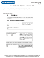
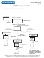
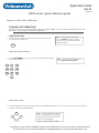
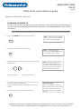
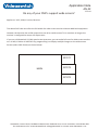
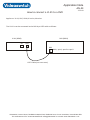
Application Note Contents AN-1 AN-2 AN-3 AN-4 AN-5 AN-6 AN-7 AN-8 AN-9 AN-10 AN-11 AN-12 AN-13 AN-14 AN-15 AN-16 AN-17 AN-18 AN-19 AN-20 AN-21 AN-22 AN-23 AN-24 AN-25 AN-26 AN-27 AN-28 AN-29 AN-30 AN-31 AN-32 AN-33 AN-34 AN-35 AN-36 AN-37 AN-38 AN-39 AN-40 AN-41 AN-42 AN-43 Netgear DG834 Router Setup for Vi-Series Zoom x3 Router Setup for Vi-Series BT 2700 HGV router setup for Vi-series Netgear DG834 Router Setup for VDM and VDC series Zoom x3 Router Setup for VDM and VDC series Upgrading Vi-series DVRs Upgrading an M-series DVR Controlling Multiple Vi305 DVRs from a Vi-K1 CMOR Upgrade procedure Eliminating hard drive issues Vi-Series DVR noise issues VDC/VDM DVR noise issues Allocating the IP address for your DVR No remote keyboard control of DVR Problems downloading incident on my LAN/WAN Drive fail message What DVRs can be used with Videoswitch keyboards How do I enable the extra camera inputs on my DVR What protocols do the VK-2, Vi-K2 and Vi-K3 keyboards support? Connecting to my DVR on my local area network How do I burn to CD/DVD on a Vi101/Vi205/Vi302/Vi305/Vi405/Vi605 I am using Pelco-D can i get into the dome menu? I have forgotten my password for my DVR? CMOR Dome Typical Installation How long will my IR lamps last? Issues with IP video server connected to Cmor dome Upgrading a VDM Digital Recorder Is it possible with one of your DVR's to view quad display on a spot output? Upgrading a VDC Digital Recorder How to wire a Cmor dome to an Axis video server. ViX05 series digital recorders(DVR) quick reference guide How many keyboard inputs are there on a DVR? What Routers do you support? What protocols does the CMOR dome support? Can you refurbish your products? I can't see coverts why? Can I connect my VDC to my network? What ports do Videoswitch DVRs use? Your DVR wont save the IP address when I press OK to save? What roughly is the image size for CIF 2 CIF 4 CIF Cat5 pin connections. Do any of your DVR's support wide screen? How to connect a Vi-K1 to a DVR Videoswitch, Ocean House, Redfields Industrial Park, Redfields Lane, Church Crookham, Hants GU52 0RD Tel: 01252-851510 Fax: 01252-851296 Email: [email protected] web: www.videoswitch.co.uk Application Note AN-1 17-5-10 Netgear DG834 ADSL Router Configuration Instructions Applies to: Vi205, Vi305, Vi405 (Vi-Series DVR) Remote Site s Connect a PC to an Ethernet port of the Netgear ADSL/router. s Power up Netgear ADSL/Router then the PC. s Open Internet Explorer, type 192.168.0.1 into the address bar, press enter. s Enter Username:'admin', Password:'password' or '1234'. The Netgear Web Console should now be displayed. s Select 'Basic Setting', check that VPI, VCI and Encapsulation settings match those supplied by your service provider. s Enter username and password, as supplied by your ISP. s Select 'Apply'. The modem/router may reboot. s A connection should now be established indicated by the Link LED on steady. s Select 'Services', (Port Forwarding). s Enter 'Name: Videoswitch', 'Type: TCP', 'Start Port: 9221' and 'End Port: 9221', then 'Apply' settings. s Select 'Firewall Rules', 'Inbound Services', Add 'Service: Videoswitch (TCP: 9221)', 'Action: Always', 'Send to LAN server: 192.168.0.50', 'WAN Users: Any', then 'Apply' settings. s Modem/Router setup complete. s Select 'Router Status' and make a note of the WAN IP address “aaa.bbb.ccc.ddd”. s It is recommended that an ADSL service with a fixed IP address is used, otherwise the WAN address may change. This WAN address is used to remotely access the Vi-Series DVR. s In Vi-Series DVR menu, enter Network; IP Address, using camera keys enter IP address s Set the IP Address in the Vi-Series DVR to: 192.168.0.50 s Sub-net Mask in the Vi-Series DVR to: 255.255.255.0 s Set the Gateway in the Vi-Series DVR to: 192.168.0.1 s Set the Port in the Vi-Series DVR to: 9221 s Connect Ethernet port from Netgear ADSL/Router to Vi-Series DVR Ethernet port. PC Site s Install Vi-Viewer onto a PC which has internet access. s Add an IP site to Vi-Viewer, specifying IP address “aaa.bbb.ccc.ddd” as above, and port 9221. s You should now be able to connect to the remote Vi-Series DVR and view images. Videoswitch, Ocean House, Redfields Industrial Park, Redfields Lane, Church Crookham, Hants GU52 0RD Tel: 01252-851510 Fax: 01252-851296 Email: [email protected] web: www.videoswitch.co.uk Application Note AN-2 17-5-10 Zoom x5 ADSL Router Configuration Instructions Applies to: Vi205, Vi305, Vi405 (Vi-Series DVR) Remote Site s Connect a PC to an Ethernet port of the Zoom ADSL/router. s Power up Zoom ADSL/Router then the PC. s Open Internet Explorer, type 10.0.0.2 into the address bar, press enter. Enter Username:'admin', Password:'zoomadsl'. The Zoom Web Console should now be displayed. s Select 'Basic Setup', check that VPI, VCI and Encapsulation settings match those supplied by your service provider. s Enter username and password, as supplied by your ISP. s Select 'Save Changes', 'Write Settings to Flash' and 'Confirm'. The modem/router will reboot. s A connection should now be established indicated by the Link LED on steady. s Select 'Advanced Setup', then 'Virtual Server', (Port Forwarding). s Enter 9221 into 'Public port' and 'Private port', select 'TCP' and 10.0.0.50 into' Host IP Address'. Select 'Add This String'. s 'Write settings to Flash' and 'Confirm'. The modem/router will restart. s ADSL/Router setup complete. s Select 'System Status' and make a note of the WAN IP address “aaa.bbb.ccc.ddd”. s It is recommended that an ADSL service with a fixed IP address is used, otherwise the WAN address may change. This WAN address is used to remotely access the Vi-Series DVR. s In Vi-Series DVR menu, enter Network; IP Address and using camera keys enter IP address. s Set the IP Address in the Vi-Series DVR to: 10.0.0.50 s Sub-net Mask in the Vi-Series DVR to: 255.255.255.0 s Set the Gateway in the Vi-Series DVR to: 10.0.0.2 s Set the Port in the Vi-Series DVR to: 9221 s Connect Ethernet port from Zoom ADSL/Router to Vi-Series DVR Ethernet port. PC Site s Install Vi-Viewer onto a PC which has internet access. s Add an IP site to Vi-Viewer, specifying IP address “aaa.bbb.ccc.ddd” as above, and port 9221. s You should now be able to connect to the remote Vi-Series DVR and view images. Videoswitch, Ocean House, Redfields Industrial Park, Redfields Lane, Church Crookham, Hants GU52 0RD Tel: 01252-851510 Fax: 01252-851296 Email: [email protected] web: www.videoswitch.co.uk Application Note AN-3 17-5-10 Setup for BT 2700 HGV router for Vi-series Applies to: Vi205, Vi305, Vi405 (Vi-Series DVR) Remote Site Vi-Series DVR network settings:s Check local IP is assigned: e.g. 192.168.0.50 s Subnet mask is in same range as IP provider: e.g. 255.255.255.0 s Gateway is set to Router IP address: e.g. 192.168.0.1 s Port set to: e.g. 9221 BT 2700 HGV Router settings:Once router has been set up for the internet with static IP complete the following: s Select firewall icon, select view details. s Select edit firewall settings, screen appears with a drop down box to select computer with 2 further boxes below (left hand = applications/ right hand = hosted applications), between them are 2 buttons “add” and “remove”. s In the select computer drop down box the names of the PC's connected will appear. The Vi-Series DVR will be shown as an unknown device, if it doesn't appear check the Vi-Series DVR network settings are correct (See notes below). s Select unknown device (this should be the Vi-Series DVR). s Under the left hand box select “add a new user defined application” s in the name box enter “Videoswitch” s Protocol:- Select TCP over UDP s Port or range: (enter port number e.g. 9221) s Protocol time out (Leave blank) s Map to host port (Leave blank) s Applications type (Leave blank) s Select OK, Screen reverts to the previous screen, in the left hand box “Videoswitch” list. s Highlight “Videoswitch” and select. s Select add to move “Videoswitch” to hosted applications box. s To save settings select “done” button at the bottom left hand corner s The Vi-Series DVR should now be able to be connected too. PC Site s Install Vi-Viewer onto a PC which has internet access. s Add an IP site to Vi-Viewer, specifying IP address “aaa.bbb.ccc.ddd” as above, and port 9221. s You should now be able to connect to the remote Vi-Series DVR and view images. Notes s Type '192.168.0.254/mdc' in your browser and press enter. s Select 'Network Tests’, select 'ping', Test: 100 times or hops, in host field put IP address of Vi-Series DVR, click 'Start’. s If test successful, go to Device List (Under 'Local Network'). s Check to see if Vi-Series DVR is now showing as an unknown device (contact BT for further support). Videoswitch, Ocean House, Redfields Industrial Park, Redfields Lane, Church Crookham, Hants GU52 0RD Tel: 01252-851510 Fax: 01252-851296 Email: [email protected] web: www.videoswitch.co.uk Application Note AN-4 17-5-10 Netgear DG834 ADSL Router Configuration Instructions Applies to: VDM/VDC Remote Site s Connect a PC to an Ethernet port of the Netgear ADSL/router. s Power up Netgear ADSL/Router then the PC. s Open Internet Explorer, type 192.168.0.1 into the address bar, press enter. s Enter Username:'admin', Password:'password' or '1234'. The Netgear Web Console should now be displayed. s Select 'Basic Setting', check that VPI, VCI and Encapsulation settings match those supplied by your service provider. s Enter username and password, as supplied by your ISP. s Select 'Apply'. The modem/router may reboot. s A connection should now be established indicated by the Link LED on steady. s Select 'Services', (Port Forwarding). s Enter 'Name: Videoswitch', 'Type: TCP', 'Start Port: 9221' and 'End Port: 9221', then 'Apply' settings. s Select 'Firewall Rules', 'Inbound Services', Add 'Service: Videoswitch (TCP: 9221)', 'Action: Always', 'Send to LAN server: 192.168.0.50', 'WAN Users: Any', then 'Apply' settings. s In 'Advanced', 'WAN Setup' MTU size should be set to 1500, then 'Apply' settings. s Modem/Router setup complete. s Select 'Router Status' and make a note of the WAN IP address “aaa.bbb.ccc.ddd”. s It is recommended that an ADSL service with a fixed IP address is used, otherwise the WAN address may change. This WAN address is used to remotely access the VDM/VDC. s In VDM/VDC menu, enter Network; IP Address, using camera keys enter IP address s Set the IP Address in the VDM/VDC to: 192.168.0.50 s Sub-net Mask in the VDM/VDC to: 255.255.255.0 s Set the Gateway in the VDM/VDC to: 192.168.0.1 s Set the Port in the VDM/VDC to: 9221 s Connect Ethernet port from Netgear ADSL/Router to VDM/VDC Ethernet port. PC Site s Install Vi-Viewer onto a PC which has internet access. s Add an IP site to Vi-Viewer, specifying IP address “aaa.bbb.ccc.ddd” as above, and port 9221. s You should now be able to connect to the remote VDM/VDC and view images. Videoswitch, Ocean House, Redfields Industrial Park, Redfields Lane, Church Crookham, Hants GU52 0RD Tel: 01252-851510 Fax: 01252-851296 Email: [email protected] web: www.videoswitch.co.uk Application Note AN-5 17-5-10 Zoom x5 ADSL Router Configuration Instructions Applies to: VDM/VDC Remote Site s Connect a PC to an Ethernet port of the Zoom ADSL/router. s Power up Zoom ADSL/Router then the PC. s Open Internet Explorer, type 10.0.0.2 into the address bar, press enter. Enter Username:'admin', Password:'zoomadsl'. The Zoom Web Console should now be displayed. s Select 'Basic Setup', check that VPI, VCI and Encapsulation settings match those supplied by your service provider. s Enter username and password, as supplied by your ISP. s Select 'Save Changes', 'Write Settings to Flash' and 'Confirm'. The modem/router will reboot. s A connection should now be established indicated by the Link LED on steady. s Select 'Advanced Setup', then 'Virtual Server', (Port Forwarding). s Enter 9221 into 'Public port' and 'Private port', select 'TCP' and 10.0.0.50 into' Host IP Address'. Select 'Add This String'. s 'Write settings to Flash' and 'Confirm'. The modem/router will restart. s ADSL/Router setup complete. s Select 'System Status' and make a note of the WAN IP address “aaa.bbb.ccc.ddd”. s It is recommended that an ADSL service with a fixed IP address is used, otherwise the WAN address may change. This WAN address is used to remotely access theVDM/VDC. s InVDM/VDC menu, enter Network; IP Address and using camera keys enter IP address. s Set the IP Address in theVDM/VDC to: 10.0.0.50 s Sub-net Mask in theVDM/VDC to: 255.255.255.0 s Set the Gateway in theVDM/VDC to: 10.0.0.2 s Set the Port in theVDM/VDC to: 9221 s Connect Ethernet port from Zoom ADSL/Router toVDM/VDC Ethernet port. PC Site s Install Vi-Viewer onto a PC which has internet access. s Add an IP site to Vi-Viewer, specifying IP address “aaa.bbb.ccc.ddd” as above, and port 9221. s You should now be able to connect to the remoteVDM/VDC and view images. Videoswitch, Ocean House, Redfields Industrial Park, Redfields Lane, Church Crookham, Hants GU52 0RD Tel: 01252-851510 Fax: 01252-851296 Email: [email protected] web: www.videoswitch.co.uk Application Note AN-6 Firmware upgrade instructions for Vi-Series DVR 17-5-10 Applies to: Vi100, VI101, VI200, VI205, VI302, VI305, VI400, VI405, VI600, Vi605 (Vi-Series DVR) Upgrade procedure: s Download the ISO disc image file from http://www.oceansystems.co.uk/FirmwareUpdates.asp by right clicking on the link and then selecting "Save target as.” Select a suitable file on your computer to save the ISO file. s Use the free utility "ISO-Burner" from http://www.oceansystems.co.uk/FreeSoftware.asp to burn the ISO file onto a new CD (or use a program such as Nero, Roxio etc ) s Insert the CD into the Vi-Series DVR. s The Vi-Series DVR will automatically ask you for confirmation to proceed with upgrade, press the OK button. s The upgrade may require you to login because it is may be password protected. s The screen will indicate that the Vi-Series DVR is being upgraded "Do not remove power" until programming has completed s After the upgrade is finished the Vi-Series DVR will restart, this indicates the upgrade is complete. s Now check that menu settings are as required. s If Vi-Series DVR reports that replay software is not installed on one or more of the hard drives, repeat the above installation sequence. s Also upgrade the Vi-Viewer and Vi-K2 software if a newer version is available and required, follow the support page http://www.oceansystems.co.uk/Support.asp for additional files. Videoswitch, Ocean House, Redfields Industrial Park, Redfields Lane, Church Crookham, Hants GU52 0RD Tel: 01252-851510 Fax: 01252-851296 Email: [email protected] web: www.videoswitch.co.uk Application Note AN-7 Firmware upgrade instructions for M-Series DVR 17-5-10 Applies to: Vi-M1, Vi-M2, Vi-M3, Vi-M4 (M-Series DVR) Upgrade procedure: Using M-Series upgrade file (USB drive required) s Download the M-Series upgrade file from http://www.oceansystems.co.uk/FirmwareUpdates.asp by right clicking on the link and then selecting "Save target as.” Select a suitable file on your USB drive to save the upgrade file. s Insert the USB drive into the M-Series DVR. s The M-Series DVR will automatically ask you for confirmation to proceed with upgrade, press the OK button. s The upgrade may require you to login because it is may be password protected. s The screen will indicate that the M-Series DVR is being upgraded "Do not remove power" until programming has completed. s After the upgrade is finished the M-Series DVR will restart, this indicates the upgrade is complete. s Now check that menu settings are as required. s Also upgrade the Vi-Viewer and Vi-K2 software if a newer version is available and required, follow the support page http://www.oceansystems.co.uk/Support.asp for additional files Using ISO image file (CD-R/CD-RW required) s Download the ISO image file from http://www.oceansystems.co.uk/FirmwareUpdates.asp by right clicking on the link and then selecting "Save target as.” Select a suitable file on your computer to save the ISO file. s Use the free utility "ISO-Burner" from http://www.oceansystems.co.uk/FreeSoftware.asp to burn the ISO file onto a new CD (or use a program such as Nero, Roxio etc ) s Insert the CD into the M-Series DVR. s The M-Series DVR will automatically ask you for confirmation to proceed with upgrade, press the OK button. s The upgrade may require you to login because it is may be password protected. s The screen will indicate that the M-Series DVR is being upgraded "Do not remove power" until programming has completed. s After the upgrade is finished the M-Series DVR will restart, this indicates the upgrade is complete. s Now check that menu settings are as required. s Also upgrade the Vi-Viewer and Vi-K2 software if a newer version is available and required, follow the support page http://www.oceansystems.co.uk/Support.asp for additional files. Videoswitch, Ocean House, Redfields Industrial Park, Redfields Lane, Church Crookham, Hants GU52 0RD Tel: 01252-851510 Fax: 01252-851296 Email: [email protected] web: www.videoswitch.co.uk Application Note AN-8 Controlling Multiple Vi305 DVRs from a Vi-K1 17-5-10 Applies to: Vi305, Vi-k1 Menu configuration s To enable multiple unit control you need to set a unit address for the Vi305's, each unit needs a different address: 1 (master), 2, 3 etc s To set the address you need too select Menu, then using the arrow keys select Configuration menu, then select Multi unit configuration. Select a unique address and select the number of linked units. Control s Press and hold “LIVE” key then press “1” key. The Vi-K1 will now be addressing unit 1. s Press and hold “LIVE” key then press “2” key. The Vi-K1 will now be addressing unit 2. s Press and hold “LIVE” key then press “3” key. The Vi-K1 will now be addressing unit 3. s Up to 10 DVR’s can be controlled from a Vi-K1 s Once you have selected the Vi305 that you want control, use the keypad as normal. Cabling s Connect the units together following the configuration drawing. s The input to the Vi305 is via the main keyboard input pins 1 & 2 s The output from the VI-K1 is via the out port pins 1 & 2 V i305 A C P O WER I N PUT M O NITO R S ALA R M S/R ELAY M S1 M onitor M O D EM 1 3 5 7 9 11 13 15 2 4 6 8 10 12 14 16 E THE RN ET CAM 2 M IC C AME RA S AU DIO O PT ION M AIN S PO T1 CAM 2 D ig it a l Vid e o R e c o r de r K EY BO A RD S LINE O UT w ww.vid eo switc h.c o.u k LIN E IN M A IN K E Y B O A R D (P in s 1 & 2) V i305 A C P OW ER I NP UT M ON ITO RS A LA RMS /RE LAY M S1 1 3 5 2 4 6 7 9 11 13 8 10 12 14 M o nito r M O D EM 15 ETH ER N ET C AM 2 16 M IC C AMER A S A U DIO O PTIO N M A IN SP O T1 C AM 2 D ig it a l Vid e o R e c o rd e r K EYB O AR D S LI NE OU T ww w.vid eo switch .co .u k LIN E IN M A IN K E Y B O A R D ( P ins 1 & 2 ) V i305 AC PO WE R IN PU T M O N ITOR S A LAR M S/R EL AY M S1 1 3 5 2 4 6 7 9 11 13 8 10 12 14 M O DE M M on itor 15 ETH ER NE T CA M 2 16 M IC CA M ER AS A UD IO OP TIO N M A IN SP OT 1 KE YB O AR DS D ig ita l V id e o R e c or de r CA M 2 LIN E O U T L INE IN www.v ide osw itch .co .uk M A IN K E Y B O A RD ( P in s 1 & 2) V i-E 2 S tar E xp an der IN OU T (P ins 1= R S 4 85 (+ ) & P in 2 = R S 48 5 ( -) Vi-K 1 Ke ybo ard Videoswitch, Ocean House, Redfields Industrial Park, Redfields Lane, Church Crookham, Hants GU52 0RD Tel: 01252-851510 Fax: 01252-851296 Email: [email protected] web: www.videoswitch.co.uk Application Note AN-9 CMOR Dome Upgrade Procedure 17-5-10 Applies to: Vi-D1 Classic, Vi-D2 Evolution, Vi-D2 Evolution-X Upgrade procedure: s s s s s s s s s s Attach RS-232 cable to the serial port of PC or use a USB to RS-232 convertor. Attach RS-232 to RS-485 convertor to RS-232 connection on PC. Connect a wire from RS-485 A+ convertor to terminal 4 (RS-485 A+) on the CMOR PSU. Connect a wire from RS-485 B- convertor to terminal 3 (RS-485 B-) on the CMOR PSU. (These are clearly marked on the PSU). Download the CMOR dome upgrade file from http://www.oceansystems.co.uk/FirmwareUpdates.asp by right clicking on the link and then selecting "Save target as.” Select a suitable directory on your PC to save the file. Open the V-Flash software, available from http://www.oceansystems.co.uk/FreeSoftware.asp by right clicking on the link and then selecting "Save target as.” Select a suitable directory on your PC to save the file, this will then need to be installed on the PC. In the V-Flash application, check baud rate is set correctly (typically 9600) and you have selected the correct Com Port for your PC. In the V-Flash application browse to the destination where you saved the upgrade file, select the file and perform the upgrade. Select upgrade and it should register on the CCTV monitor that the upgrade is in progress. When the upgrade is complete the units will reset, on power-up it will display the configuration. Check that the version of software is correct. Videoswitch, Ocean House, Redfields Industrial Park, Redfields Lane, Church Crookham, Hants GU52 0RD Tel: 01252-851510 Fax: 01252-851296 Email: [email protected] web: www.videoswitch.co.uk Application Note AN-10 Eliminating hard drive issues 17-5-10 Applies to: VDC/VDM and Vi-Series DVR’s I have a new hard drive but still get critical alert ‘drive fail’. s If you come across this it may be that the tray has failed. At this point you may have to purchase a new tray and bay to eliminate the problem. s If the DVR is a dual or triple drive system then you can swap the trays and drives around, in the bays to find what part is causing the issue. I have a new drive but on screen it keeps showing installation of replay files required. s On all of our hard drives we install some replay files so that when you burn an incident to CD/DVD or USB the replay files are also transferred. s If a drive does show this message you can download the latest firmware for that product from our website http://www.oceansystems.co.uk/FirmwareUpdates.asp I have critical alert ‘drive fail’ on screen and record stopped. s Check the drive tray is fully pushed into drive bay and locked, these are messages you would expect to see if it is not. Videoswitch, Ocean House, Redfields Industrial Park, Redfields Lane, Church Crookham, Hants GU52 0RD Tel: 01252-851510 Fax: 01252-851296 Email: [email protected] web: www.videoswitch.co.uk Application Note AN-11 Vi-Series DVR noise issues 17-5-10 Applies to: Vi-Series DVR’s If the DVR becomes noisy after they have been installed for a long period of time check the following: s The fans can become fairly noisy after a long period of time. They are in a product that is running 24 hours 7 days a week, often in a dusty environment. If the fans are making a noise it is possible to replace them to resolve the problem. See below for replacement service parts. If the drive trays have 2 Led's on the left hand side then the fans will be behind the tray. By unlocking and pulling out the tray you should be able to see the fans. If the tray has a flat lock instead of a round lock the fans are in the front of the tray. s The hard drives can also become noisy and a clicking noise can occur. If this happens replace the drive. See below for replacement service parts. s If the functionality of the machine seems different or is running very slow then the drive(s) could be failing or about to fail. If whilst pressing keys it takes a long time to respond this is may be a drive problem and will need replacing. See below for replacement service parts. s On older machines it is not always possible to replace the drives or fans with the same parts as the parts are no longer available. If this is the case, you may be able to upgrade to a new style bays/trays that support SATA hard drives. Replacement service parts: These are available from http://www.oceansystems.co.uk/products.asp?cat=8 Videoswitch, Ocean House, Redfields Industrial Park, Redfields Lane, Church Crookham, Hants GU52 0RD Tel: 01252-851510 Fax: 01252-851296 Email: [email protected] web: www.videoswitch.co.uk Application Note AN-12 VDC/VDM DVR noise issues 17-5-10 Applies to: VDC/VDMs DVR’s If the DVR becomes noisy after they have been installed for a long period of time check the following: s The fans can become fairly noisy after a long period of time. They are in a product that is running 24 hours 7 days a week, often in a dusty environment. If the fans are making a noise it is possible to replace them to resolve the problem. See below for replacement service parts. If the drive trays have 2 Led's on the left hand side then the fans will be behind the tray. By unlocking and pulling out the tray you should be able to see the fans. If the tray has a flat lock instead of a round lock the fans are in the front of the tray. s The hard drives can also become noisy and a clicking noise can occur. If this happens replace the drive. See below for replacement service parts. s If the functionality of the machine seems different or is running very slow then the drive(s) could be failing or about to fail. If whilst pressing keys it takes a long time to respond this is may be a drive problem and will need replacing. See below for replacement service parts. s On older machines it is not always possible to replace the drives or fans with the same parts as the parts are no longer available. If this is the case, you may be able to upgrade to a new style bays/trays that support SATA hard drives. Replacement service parts: These are available from http://www.oceansystems.co.uk/products.asp?cat=8 Videoswitch, Ocean House, Redfields Industrial Park, Redfields Lane, Church Crookham, Hants GU52 0RD Tel: 01252-851510 Fax: 01252-851296 Email: [email protected] web: www.videoswitch.co.uk Application Note AN-13 Allocating the IP address for your DVR 17-5-10 Applies to: VDC/VDM, Vi-Series and M-Series DVR’s s Open a command prompt. Click, Start->All programs->Accessories->Command prompt. You will now have a window appear with a cursor flashing. s Find out the IP address of your PC. From the command prompt, type: ipconfig and press the return/enter key, this will give the IP address of your PC. For example if your PC’s IP address is 192.168.0.2 You will need to give your DVR an IP address such as 192.168.0.50 (default). First you will need to ensure this address is free to use, it could be allocated to another PC or device. s Checking if an IP address is in use. From the command prompt, type ping and then the IP address you are considering using. Example: ping 192.168.0.50 If you get a reply it means this IP address is being used. If it says Destination net unreachable then you can use this IP address. You can only change the last 3 digits of the IP address 192.168.0.xxx s If the customer wishes to remotely access via broadband they will need a fixed IP address from their Internet Service Provider (ISP). This will be assigned to their router, see router application notes for configuration http://www.oceansystems.co.uk/ApplicationNotes.asp s You will need to download the viewer from http://www.oceansystems.co.uk/FreeSoftware.asp for remotely viewing from the DVR. Videoswitch, Ocean House, Redfields Industrial Park, Redfields Lane, Church Crookham, Hants GU52 0RD Tel: 01252-851510 Fax: 01252-851296 Email: [email protected] web: www.videoswitch.co.uk Application Note AN-14 No remote keyboard control of DVR 17-5-10 Applies to: Vi-K1, Vi-K2 or a Vk-2 (remote keyboard) If when you select a different camera on a Vi-K2 or Vi-K3 keyboard and the LED/LCD display changes but the monitor screen does not: Try the following steps: s s s s s s First check that the Cat-5 cable is plugged into the OUT of the keyboard, as this is data output from the keyboard. Check the other end of the Cat-5 cable is plugged into either the MAIN or one of the SPOT ports of the DVR. Make sure the CAT5 cable is not a cross-over cable. Try another cable. Check that the unit number set in the DVR configuration is “Master” (i.e. 1) or that you have specified the correct unit number on the keyboard. In the case of a Vi-K1, press ALT and 1,2,3 etc to selct units 1,2,3 etc. Try testing with a shorter length of Cat-5 by moving the remote keyboard to the DVR. Otherwise you may have a fault with the equipment, this will need to be sent back for repair. Videoswitch, Ocean House, Redfields Industrial Park, Redfields Lane, Church Crookham, Hants GU52 0RD Tel: 01252-851510 Fax: 01252-851296 Email: [email protected] web: www.videoswitch.co.uk Application Note AN-15 Problems downloading incident on my LAN/WAN 17-5-10 Applies to: VDC/VDM, Vi-Series DVR I am able to connect to my DVR but I am not able to download the incident. Make sure your DVR has the latest firmware installed, this can be download from http://www.oceansystems.co.uk/FirmwareUpdates.asp Make sure you are using the latest Vi-Viewer on your PC, this can be downloaded from http://www.oceansystems.co.uk/FreeSoftware.asp Try rebooting the DVR by switching off for 10 seconds, then switching back on again. Videoswitch, Ocean House, Redfields Industrial Park, Redfields Lane, Church Crookham, Hants GU52 0RD Tel: 01252-851510 Fax: 01252-851296 Email: [email protected] web: www.videoswitch.co.uk Application Note AN-16 What DVR’s can be used with Videoswitch keyboards 17-5-10 Applies to: VDC/VDM, Vi-Series, M-series DVR’s What DVR can I use with your keyboards? sThe Vk-1 and Vk-2 keyboards work with the VDC/VDM DVR’s. sThe Vi-K1, Vi-K2 and Vi-K3 keyboards work with the Vi-Series DVR. sThe Vi-K1, Vi-K2 and Vi-K3 keyboards work with the M-Series DVR. Keyboard information sThe Vk-1 and Vi-K1 do not have built in telemetry but do give the operator full control of the DVR. sThe Vk-2, Vi-K2 and Vi-K3 all have built-in telemetry for controlling fully functional domes directly. sThe Vk-2, Vi-K2 and Vi-K3 can also control domes via a Videoswitch DVR and also give full control of a Videoswitch DVR. Videoswitch, Ocean House, Redfields Industrial Park, Redfields Lane, Church Crookham, Hants GU52 0RD Tel: 01252-851510 Fax: 01252-851296 Email: [email protected] web: www.videoswitch.co.uk Application Note AN-17 Drive Fail Message 17-5-10 Applies to: VDC/VDM, Vi-Series DVR’s Drive Fail message on screen. s s s Check power LED on drive(s) are on, if the power LED is off it would indicate the drive may be unlocked. This would show as a critical alert. Turn DVR’s power off, then lock the drive tray. Turn power back on, the power LED should illuminate, then critical alert should now be cleared. If you have a dual or triple drive DVR, if one of the drive trays does not have a drive fitted, this would also show as a critical alert. Access the DVR menu and go to Alarm sub-menu, you can disable the drive fail alert for this drive. We recommend this is only done if there is no drive in the tray. Videoswitch, Ocean House, Redfields Industrial Park, Redfields Lane, Church Crookham, Hants GU52 0RD Tel: 01252-851510 Fax: 01252-851296 Email: [email protected] web: www.videoswitch.co.uk Application Note AN-18 How do I enable the extra camera inputs on my DVR? 17-5-10 Applies to: Vi-Series, M-series DVRs If you have one of our Vi-Series DVR’s and you have noticed there are additional unused camera inputs it is possible to upgrade the DVR so all inputs can be used. Vi-series DVR: you can purchase an upgrade code from Videoswitch and follow the instruction below. When you purchase the upgrade, you must let us know the serial number of the DVR. The upgrade will only work for that DVR. s s s s s s s Ensure Vi-Series DVR is powered up. Eject the CD draw and place an upgrade CD into the DVR. After a few seconds, a blue screen will appear asking to enter the upgrade code. Enter the following code: XXXXXXXXXX as stated on the supplied upgrade CD. Now press the OK button. The Vi-Series DVR will start to upgrade. This may take a few minutes. When the upgrade has finished, the unit will reboot itself and the blue upgrade screen will reappear. When this happens, eject the CD from the Vi-Series DVR and live images will appear. To check if the Vi-Series DVR has been upgraded successfully, press the info button and check if the DVR model has been upgraded to what you expected. M-series DVR: An additional 4-camera channel card must be fitted to upgrade an M-series DVR. This can be done by a competant engineer, or the DVR can be returned to Videoswitch for the upgrade. Contact Videoswitch for details. Camera upgrade options Model VDC: Vi101,Vi-102,Vi-200,Vi-205 Vi305,Vi405 Starting cameras 4 4,6 12 Upgrade to 9 10 16 Videoswitch, Ocean House, Redfields Industrial Park, Redfields Lane, Church Crookham, Hants GU52 0RD Tel: 01252-851510 Fax: 01252-851296 Email: [email protected] web: www.videoswitch.co.uk Application Note AN-19 17-5-10 What protocols do the VK-2, Vi-K2 and Vi-K3 keyboards support? Applies to: VK-2, Vi-K2, Vi-K3 These keyboards support the protocols in the table belowwhen driving domes directly. There are two dome outputs, so two different dome protocols can be used at once on the same system. When driving domes via a Videoswitch DVR, the protocols depend on the DVR. The Vi-series support all these and also BBV up-the-coax The M-series supports Pelco-D and BBV up-the-coax Protocol Number Protocol Output Used Comments 1 Slave RS485 Select this protocol in all slave VK2’s. 2 JVC RS485 Direct connection via twisted pair. 3 Molynx RS485 Connect directly to Molynx receivers via twisted pair. 4 Dennard RS485 Direct connection via twisted pair. 5 VCL RS485 Direct connection via twisted pair. 6 Sanyo RS485 Direct connection via twisted pair. 7 BBV RS232 Connect to a BBV transmitter such as the TX1000/8, which provides control of BBV compatible domes & receivers via coax. 8 BBV 20mA Connection to BBV compatible receivers via twisted pair. The RX100 receivers provide coax or RS485 control of a range of dome domes as supported by BBV. 9 Forward Vision (VCL) RS485 Direct connection via twisted pair. Note that the dome must be purchased with the VCL-based protocol option. 10 Mercer RS485 Direct connection via twisted pair. 11 Merit Lilin RS485 Direct connection via twisted pair. 12 Borsatec RS485 Direct connection via twisted pair. 13 Samsung RS485 Direct connection via twisted pair. 14 Pelco-D RS485 Direct connection via twisted pair. 15 VXP4 RS485 Direct connection via twisted pair. 16 SpeedDome (VCL) RS485 Direct connection via twisted pair. 17 ForwardVision (FV) RS485 Direct connection via twisted pair. Videoswitch, Ocean House, Redfields Industrial Park, Redfields Lane, Church Crookham, Hants GU52 0RD Tel: 01252-851510 Fax: 01252-851296 Email: [email protected] web: www.videoswitch.co.uk Application Note AN-20 Connecting to my DVR on my local area network 17-5-10 Applies to: VDM, VDC, Vi-series, M-series To control a Videoswitch DVR and view images across a local area network (LAN) you need to install viewer software on a PC: VDM or VDC: Vi-series: M-series: VDM connect Vi-Viewer Vi-Viewer with MPEG4 You can download the viewer software free from our website: http://www.oceansystems.co.uk/FreeSoftware.asp It is recommended that you upgrade the firmware in you DVR to the latest version which can be downloaded free from our website: http://www.oceansystems.co.uk/FirmwareUpdates.asp Install the view software on you PC (Macs are not supported) Set the IP address on you DVR to an suitable unused one. If there is an IT department you may need to ask them to allocate one. Press connect on the viewer and add the DVR as a new site. You will need to enter the IP address that you have programmed into the DVR. You will also need to make the the port number is the same as set in the DVR. Normally the default port number can be used. Click on “Connect” and You should now be able to connect to the DVR and view images Videoswitch, Ocean House, Redfields Industrial Park, Redfields Lane, Church Crookham, Hants GU52 0RD Tel: 01252-851510 Fax: 01252-851296 Email: [email protected] web: www.videoswitch.co.uk Application Note AN-21 How do I burn to CD/DVD on a Vi-series DVR 17-5-10 Applies to: Vi101, Vi102, Vi200, Vi400, Vi-600, Vi205, Vi-305, Vi-405, Vi605 Extract from user manual: Videoswitch, Ocean House, Redfields Industrial Park, Redfields Lane, Church Crookham, Hants GU52 0RD Tel: 01252-851510 Fax: 01252-851296 Email: [email protected] web: www.videoswitch.co.uk Application Note AN-22 I am using Pelco-D - can I get into the dome menu? 17-5-10 Applies to: Vi-K2, Vi-K3, VK-2 sYes the Vi-k2/Vi-k3/Vk-2 has a special mode to make access to dome menus very easy. sPress the DOME key on the Vi-K2/Vi-K3/VK-2 sThe letters DO will appear on the display sWhile the DO is being displayed, some of the keys on the Vi-K2/Vi-K3/VK-2 have special functions as follows: sPress the MENU key to enter the dome user menu sUse the UP, DOWN, LEFT, RIGHT arrow keys to navigate within the dome menu sPress the OK (Yes) key to enter a sub-menu or to accept a menu settings Videoswitch, Ocean House, Redfields Industrial Park, Redfields Lane, Church Crookham, Hants GU52 0RD Tel: 01252-851510 Fax: 01252-851296 Email: [email protected] web: www.videoswitch.co.uk Application Note AN-23 I have forgotten my password for my DVR 17-5-10 Applies to: VDM, VDC, Vi-series, M-series Videoswitch can supply back-door passwords to gain access to DVRs. If you have forgotten you password, please: sFind out the serial number of the DVR. This is located on the ratings label under the DVR. It is can also be seen on the monitor by pressing the HELP or INFO key. You will need to press the HELP key again or the RIGHT arrow key to access the system configuration screen. sEmail or telephone Videoswitch to request a backdoor password. You will need to tell us the serial number of the unit. Videoswitch, Ocean House, Redfields Industrial Park, Redfields Lane, Church Crookham, Hants GU52 0RD Tel: 01252-851510 Fax: 01252-851296 Email: [email protected] web: www.videoswitch.co.uk Application Note AN-24 17-5-10 CMOR Dome Typical Installation Applies to: CMOR Vi-D1 Classic, Vi-D2 Evolution and Evolution-X Vi-K2 KEYBOARD M-series or Vi-405 DVR Mains Power Twisted Pair Twisted Pair Vi-E2 Star Expander (8 outputs, may be cascaded) COAX and optional twisted pair COAX and optional twisted pair Vi-AL1 Alarm Module (optional) Vi-PSU1 PSU COAX and optional twisted pair Mains Power CMOR Umbilical cable CMOR Dome Vi-AL1 Alarm Module (optional) Vi-PSU1 PSU Vi-AL1 Alarm Module (optional) Vi-PSU1 PSU CMOR Umbilical cable Mains Power CMOR Umbilical cable CMOR Dome Mains Power CMOR Dome Note: when using a star expander as in this example, terminate all alarm modules and all domes Videoswitch, Ocean House, Redfields Industrial Park, Redfields Lane, Church Crookham, Hants GU52 0RD Tel: 01252-851510 Fax: 01252-851296 Email: [email protected] web: www.videoswitch.co.uk Application Note AN-25 How long will my CMOR IR lamps last? 17-5-10 Applies to: CMOR Vi-D1 Classic, Vi-D2 Evolution sThe IR lamps are covered by a 2 year warranty sThe IR light out will degrade with time at a rate of approximately 3% per year. sThe manufacturer’s data indicates that after 10 years the light output will have decrease to about 70% of the original value sThese are typical figures and individual LED lamps may differ sLamps can be replaced by Videoswitch should they fail or exihbit significant reduction in light output Videoswitch, Ocean House, Redfields Industrial Park, Redfields Lane, Church Crookham, Hants GU52 0RD Tel: 01252-851510 Fax: 01252-851296 Email: [email protected] web: www.videoswitch.co.uk Application Note AN-26 Issues with IP video server connected to CMOR dome 17-5-10 Applies to: CMOR Dome, Axis IP server sIf the images exhibit flickering, it may be that the server is not quite sensitive enough. sTurn up the video gain in the CMOR dome and the flickering should cease. Videoswitch, Ocean House, Redfields Industrial Park, Redfields Lane, Church Crookham, Hants GU52 0RD Tel: 01252-851510 Fax: 01252-851296 Email: [email protected] web: www.videoswitch.co.uk Application Note AN-27 Upgrading a VDM Digital Recorder 17-5-10 Applies to: VDM-16 1. Download the ISO disc image file from the internet: http://www.oceansystems.co.uk/FirmwareUpdates.asp by right clicking on the link and then selecting "Save target As.” Select a suitable location on your computer to save the ISO file. 2. Use a CD burner such as Nero or Roxio to burn the upgrade file onto CD. You may also use the free utility "ISO-Burner" which may be downloaded form our web site: http://www.oceansystems.co.uk/FreeSoftware.asp 3. Insert the upgrade CD that you have created CD into the DVR. 4. Press “Setup” key and select “User” menu then select “Upgrade from CD” using the arrow keys. 5. Do not remove power until programming has been completed this will corrupt the file. 6. If you're VDM contains firmware that pre-dates VDM001gb or VDM002a7 it will not recognise the update CD. If this is the case, first upgrade using Vsd901v.iso, then upgrade again to the latest version. Videoswitch, Ocean House, Redfields Industrial Park, Redfields Lane, Church Crookham, Hants GU52 0RD Tel: 01252-851510 Fax: 01252-851296 Email: [email protected] web: www.videoswitch.co.uk Application Note AN-28 Is it possible to view quad display on a DVR spot output? 17-5-10 Applies to: VDM, VDC, Vi-series, M-series No, the spot monitor outputs are not capable of displaying a quad view. The main monitor output can display full screen, quad, 9-way split or 16-way split. If you require additional quad views, this can be achieved by adding one or more Videoswitch quad processor such as the Vi-P14. The Vi-P14 has loop-through video BNC connectors (as do some of the DVRs) so it is easy to loop through the camera signals to both the DVR and the quad processor. Videoswitch, Ocean House, Redfields Industrial Park, Redfields Lane, Church Crookham, Hants GU52 0RD Tel: 01252-851510 Fax: 01252-851296 Email: [email protected] web: www.videoswitch.co.uk Application Note AN-29 Upgrading a VDC DVR 17-5-10 Applies to: VDC-4 or VDC-9 1. Download the ISO disc image file from the internet: http://www.oceansystems.co.uk/FirmwareUpdates.asp by right clicking on the link and then selecting "Save target As.” Select a suitable location on your computer to save the ISO file. 2. Use a CD burner such as Nero or Roxio to burn the upgrade file onto CD. You may also use the free utility "ISO-Burner" which may be downloaded form our web site: http://www.oceansystems.co.uk/FreeSoftware.asp 3. Insert the upgrade CD that you have created CD into the DVR. 4. Press the “Setup” key and using the arrow keys select “Config” and then select "Upgrade from CD in the menu the screen will indicate that the upgrade is in progress. 5. Do not remove power until programming has been completed this will corrupt the file. 6. When the unit restarts the upgrade is complete. Videoswitch, Ocean House, Redfields Industrial Park, Redfields Lane, Church Crookham, Hants GU52 0RD Tel: 01252-851510 Fax: 01252-851296 Email: [email protected] web: www.videoswitch.co.uk Application Note AN-30 How to wire a Cmor dome to an Axis video server 17-5-10 Applies to: CMOR Vi-D1 Classic, Vi-D2 Evolution and Evolution-X sGo through the setup of the Axis module from the Axis manual. sDownload the PTZ drivers for Pelco-D sSet up the CMOR Dome’s protocol to Pelco-D. If it is a Vi-D2 Evolution, auto-protocol detection will automatically detect the protocol s If a CMOR Vi-A16 alarm card is being used, set it’s protocol to Pelco-D sMake sure the baud rate of the Axis server, the dome and the alarm card (if fitted) are all the same. The default for Pelco-D is 2400 baud sConnect the Rs485 output of the Axis server to the CMOR dome PSU. Videoswitch, Ocean House, Redfields Industrial Park, Redfields Lane, Church Crookham, Hants GU52 0RD Tel: 01252-851510 Fax: 01252-851296 Email: [email protected] web: www.videoswitch.co.uk Application Note AN-31 ViX05 series quick reference guide 17-5-10 Applies to: Vi205, Vi305, Vi405 DVRs L IVE VIEW ING This DVR will normally be recording liv e images all the time irrespective of whether im ages are being played back or written to CD (unless specifically setup to use tim ers). Passw ord If a p asswo rd is req uired, press the passwo rd key follow ed by yo ur six d igit passw ord. Then press the OK bu tto n to log yo u into the system. Fo r example: PSW 1 1 1 1 1 1 OK Viewing Full Screen Im ages Press the live key to view live im ages on the main mon ito r.This key may be pressed at any time to exit from an y other screen. LIV E Select full screen view s o f differen t cameras on the main monito r by entering the camera nu mber using the NUM BER keys: Note: The INC and DEC keys may b e used to step forw ard s o r backwards thro ught the cam eras. M ulti Screen Displays Press the Qu ad key to view 4 cameras o n the monitor at o nce. Press the k ey again to see th e next 4 cameras. Press the Multi-screen key to view 9 cameras o n the mo nitor at on ce. Press it again to view 16 cameras at once (maximum number of cameras d ep en ds o n model of DVR) Spot M onitor To choose the camera d isp layed on the spot monito r, use these keys to step backw ards and forw ards th rough the cameras: Videoswitch, Ocean House, Redfields Industrial Park, Redfields Lane, Church Crookham, Hants GU52 0RD Tel: 01252-851510 Fax: 01252-851296 Email: [email protected] web: www.videoswitch.co.uk Application Note AN-31 ViX05 series quick reference guide 17-5-10 Applies to: Vi205, Vi305, Vi405 DVRs F IN D IN G IN F O R M ATIO N I f th e re is a C D in th e C D d ri v e w ith pre v i ou s ly s to red im a g e s o n i t, th e D VR w il l re pl a y fr om th e C D . O th e rw i se , it w il l re p la y f ro m t he bu i lt- in h a rd d riv e . F IN D D ate /T im e T his m ode finds im ages by date and tim e. Press this key to enter the D ate/Tim e sea rch m o de: N ote: Som etim es it is useful to pr ess the DE F key w hen in sea rch m o de, to ca ll up the latest a vaila ble rec orded im ag es F IN D Find b y entering d at e and t im e U se the N U M BE R keys to enter any date an d tim e for w hich there is still video ava ilable. N ote: The fo rm at fo r the d ate and tim e is DD/M M /YY HH:M M :SS Find b y A ctiv e Searc h Sc roll thro ugh da tes a nd tim es using the left a nd righ t A RR OW keys: then increa se or d ec rea se yo ur specified var iable using the up and dow n ARR OW keys. No te: As an y digit of the da te a nd tim e is c hang ed , the correspon ding im age is im m ediately foun d on the hard drive and d isp layed. This is ou r “ac tive searc h” fa cility. Videoswitch, Ocean House, Redfields Industrial Park, Redfields Lane, Church Crookham, Hants GU52 0RD Tel: 01252-851510 Fax: 01252-851296 Email: [email protected] web: www.videoswitch.co.uk Application Note AN-31 ViX05 series quick reference guide 17-5-10 Applies to: Vi205, Vi305, Vi405 DVRs B U R N IN G IN C ID E N TS To b urn a sec tion of v id eo recording to C D, g o to t he mid dle section o f th e v ideo or to the particular image that y ou wish to backu p using th e FIN D an d PLA Y facilities as described in the FIND IN FORM ATION sec tio n. Th en do th e follo wing : C all up the BU RN - 1 screen by pr essing this key. No te: If there is a CD in the C D drive that is not blank, the B UR N screen will no t be d isplayed. B URN C reate a n “in cident” by p ressing this key. DE F C hang e the du ration o f the incident a s requ ired using the left/rig ht keys: Less tim e recorded N ot e: The tim e and Da te selected on the find screen w ill be in the m id dle o f this incident. No te: The sta rt and end tim es can also be individ ually set a nd m ultiple incid ents m a y b e bur ned onto a single CD. Please refer to the m a in m an ual fo r details. M ore tim e reco rded Pr ess the “O pen CD draw er” button o n the C D drive a nd pla ce a ne w CD-R in the CD drive. Pr ess the “O pen CD draw er” button a gain to close the dr aw er. Sta rt writing to a bla nk CD by pressing this key: IM PO RTA N T N OTE: When a n im porta nt incid ent ha s been written to a CD, alwa ys check that the CD plays ba ck co rrectly, eith er by p laying it o n th e DVR o r on a P C. OK Videoswitch, Ocean House, Redfields Industrial Park, Redfields Lane, Church Crookham, Hants GU52 0RD Tel: 01252-851510 Fax: 01252-851296 Email: [email protected] web: www.videoswitch.co.uk Application Note AN-32 How many keyboard inputs are there on a Vi205? 17-5-10 Applies to: Vi-205 sThere are two: a main input and a spot input sThe Main keyboard input will give you full control of the DVR and control the main monitor output sThe Spot keyboard input will give you control of the spot monitor output sYou can connect these keyboard inputs to a Vi-K1, Vi-K2 or Vi-K3 keyboard using a CAT5 cable sOver a distance of 100 metres or less, the CAT5 will carry the video and power to the keyboards from the DVR, and data back from the keyboard to the DVR. A monitor may be plugged into the BNC connector on the keyboard. sFor longer cable runs (up to 1000m) it will be necessary to send the video from the corresponding BNC output (main or spot) on the DVR via coax cable to the remote monitor. It will also be necessary to power the keyboard using the mains adaptor supplied. sNote that Vi-K2 and Vi-K3 keyboards should always be powered by the mains adaptor. Videoswitch, Ocean House, Redfields Industrial Park, Redfields Lane, Church Crookham, Hants GU52 0RD Tel: 01252-851510 Fax: 01252-851296 Email: [email protected] web: www.videoswitch.co.uk Application Note AN-33 What Routers do you support? 17-5-10 Applies to: VDC, VDM, Vi-series and M-series DVRs We have application notes that hep you set up these brands of router: sNetgear sZoom sBT Applications notes may be found on our website at this location: http://www.oceansystems.co.uk/ApplicationNotes.asp Most other routers will work perfectly well but we cannot provide addition information for their use. Videoswitch, Ocean House, Redfields Industrial Park, Redfields Lane, Church Crookham, Hants GU52 0RD Tel: 01252-851510 Fax: 01252-851296 Email: [email protected] web: www.videoswitch.co.uk Application Note AN-34 What protocols does the CMOR dome support? 17-5-10 Applies to: CMOR Vi-D1 Classic, Vi-D2-Evolution and Evolution-X The CMOR Vi-D1 Classic and Vi-D2 Evolution and Evolution-X domes support the following protocols and standard baud rates: s BBV up-the-coax sVideoswitch VXP4 9600 baud sPelcoP 4800 baud sPelcoD 2400 baud sVista 9600 baud The dome also support non-standard baud rates for all protocols: 2400, 4800 or 9600 baud. Videoswitch, Ocean House, Redfields Industrial Park, Redfields Lane, Church Crookham, Hants GU52 0RD Tel: 01252-851510 Fax: 01252-851296 Email: [email protected] web: www.videoswitch.co.uk Application Note AN-35 Can you refurbish your products? 17-5-10 Applies to: All products sYes, we can refurbish all Videoswitch products subject to availability of spare parts. sWe replace any worn or failed parts, upgrade software and perform a comprehensive system test. sPlease contact our service department for a quote. We will require product type and serial number. Videoswitch, Ocean House, Redfields Industrial Park, Redfields Lane, Church Crookham, Hants GU52 0RD Tel: 01252-851510 Fax: 01252-851296 Email: [email protected] web: www.videoswitch.co.uk Application Note AN-36 I can't see coverts why? 17-5-10 Applies to: VDC, VDM, Vi-series, M-series sIf you have set coverts, only users with the sufficient access rights will be able to view them. sAccess rights are set in the menu in the Passwords section sTo view coverts, you must log-on by pressing the PSW key, entering the password then pressing the OK key. sAs long as you have logged on and have the correct rights assigned in the menu, you will now be able to view Coverts. sWhen you have finished viewing the coverts, press the PSW key then the OK key to log you off. You will also automatically log off if you do not press any key for a period of time (typically 10 minutes). Videoswitch, Ocean House, Redfields Industrial Park, Redfields Lane, Church Crookham, Hants GU52 0RD Tel: 01252-851510 Fax: 01252-851296 Email: [email protected] web: www.videoswitch.co.uk Application Note AN-37 Can I connect my VDC to my network? 17-5-10 Applies to: VDC-4, VDC-9 If the Ethernet has been fitted in your VDC, you can access the DVR using our free viewing software which can be downloaded free from our web site: http://www.oceansystems.co.uk/FreeSoftware.asp sYou can check if Ethernet is enabled by pressing and holding the ALT key then pressing the SETUP key. It will say on the screen whether Ethernet is fitted or not. sIf it Ethernet is not fitted please contact our service department. Ethernet can be retrospectively fitted to the VDC. Videoswitch, Ocean House, Redfields Industrial Park, Redfields Lane, Church Crookham, Hants GU52 0RD Tel: 01252-851510 Fax: 01252-851296 Email: [email protected] web: www.videoswitch.co.uk Application Note AN-38 What ports do Videoswitch DVRs use? 17-5-10 Applies to: VDC, VDM, Vi-series, Vi-M series DVRs sVideoswitch DVRs can be set to use any ports. Port numbers, together with IP addresses are set in the “Network” menu. You should however avoid port numbers for data and command that have predefined usage, in notably 80 and 8080. If you keep to ports in the 9000 - 9999 range you should have no problems. sVDC, VDM, Vi-series default port settings: Command and data: 9221 sM-series default port settings: Command: 9112 Data: 9113 Web browsing: 80 FTP Incident Upload 21 sWhen setting up a router, the port settings are set in the DVR must set in the router network address translation (NAT) table. Videoswitch, Ocean House, Redfields Industrial Park, Redfields Lane, Church Crookham, Hants GU52 0RD Tel: 01252-851510 Fax: 01252-851296 Email: [email protected] web: www.videoswitch.co.uk Application Note AN-39 DVR won’t save the IP address when I press OK to save? 17-5-10 Applies to: VDC, VDM, Vi-series Once you have entered the IP address simply press the LIVE key and it will automatically be saved. Videoswitch, Ocean House, Redfields Industrial Park, Redfields Lane, Church Crookham, Hants GU52 0RD Tel: 01252-851510 Fax: 01252-851296 Email: [email protected] web: www.videoswitch.co.uk Application Note AN-40 What roughly is the image size for CIF, 2CIIF and 4CIF (D1) 17-5-10 Applies to: VDM, VDM, Vi-Series M-series Vi-Series DVRs The average image size depends on the quality setting and how complex the image is. Typical sizes are: 2CIF 15 - 40Kbytes M-series DVRS The average image size depends on the quality setting, how complex the image is and how much movement there is. Typical sizes are: CIF 2CIF 4CIF (D1) 3 to 6 Kbytes 6 to 12 Kbytes 12 to 24 Kbytes Videoswitch, Ocean House, Redfields Industrial Park, Redfields Lane, Church Crookham, Hants GU52 0RD Tel: 01252-851510 Fax: 01252-851296 Email: [email protected] web: www.videoswitch.co.uk Application Note AN-41 CAT5 Keyboard Pin Connections 17-5-10 Applies to: VDC, VDM, Vi-series, M-series, Vk1, VK-2, Vi-K1, Vi-K2, Vi-K3 DVR Keyboard Ports for connection to keyboard (and also keyboard loop “In” port) Pin 1 2 3 4 5 6 7 8 Signal RS485+(A) input from keyboard RS485-(B) input from keyboard RS485+(A) output to keyboard +9V power output to keyboard 0V power output to keyboard RS485+(B) output to keyboard Twisted-pair video+ output to keyboard Twisted-pair video- output to keyboard CAT Cable Colour (EIA/TIA 568B) White with Orange stripes Orange White with Green stripes Blue White with Blue stripes Green White with Brown stripes Brown Keyboard “Out” ports for connection to DVR: Pin 1 2 3 4 5 6 7 8 Signal RS485+(A) output to DVR RS485-(B) output to DVR RS485+(A) input from DVR +9V power from DVR 0V power from DVR RS485+(B) input from DVR Twisted-pair video+ input from DVR Twisted-pair video- input from DVR CAT Cable Colour (EIA/TIA 568B) White with Orange stripes Orange White with Green stripes Blue White with Blue stripes Green White with Brown stripes Brown Videoswitch, Ocean House, Redfields Industrial Park, Redfields Lane, Church Crookham, Hants GU52 0RD Tel: 01252-851510 Fax: 01252-851296 Email: [email protected] web: www.videoswitch.co.uk Application Note AN-42 Do any of your DVR's support wide screen? 17-5-10 Applies to: VDC, VDM, Vi-series, M-series The above DVR`s do not utilise the full width of a wide screen monitor without additional equipment. However the M-series has a VGA output that can drive a wide screen TV or monitors as long as the monitor is configured to accept 4:3 aspect ratio. If you use a Videoswitch Vi-P14A quad screen processor, you can make full use of a wide-screen monitor on a Vi-M3, Vi-M4 or Vi-405 DVR by programming it to display multiple images on the wide-screen format (select 16:9 format) as shown below: SPOT1 MAIN SPOT2 SPOT3 Videoswitch, Ocean House, Redfields Industrial Park, Redfields Lane, Church Crookham, Hants GU52 0RD Tel: 01252-851510 Fax: 01252-851296 Email: [email protected] web: www.videoswitch.co.uk Application Note AN-43 How to connect a Vi-K1 to a DVR 17-5-10 Applies to: Vi-K1, VDC, VDM, Vi-series, M-series The Vi-K1 is can be connected to the DVR by a CAT5 cable as follows: DVR (REAR) Vi-K1 (REAR) IN OUT KBD Main, spot1, spot2 or spot3 CAT5 Cable (not cross-over) Videoswitch, Ocean House, Redfields Industrial Park, Redfields Lane, Church Crookham, Hants GU52 0RD Tel: 01252-851510 Fax: 01252-851296 Email: [email protected] web: www.videoswitch.co.uk Application Note AN-44 Title 17-5-10 sText Videoswitch, Ocean House, Redfields Industrial Park, Redfields Lane, Church Crookham, Hants GU52 0RD Tel: 01252-851510 Fax: 01252-851296 Email: [email protected] web: www.videoswitch.co.uk Application Note AN-45 Title 17-5-10 sText Videoswitch, Ocean House, Redfields Industrial Park, Redfields Lane, Church Crookham, Hants GU52 0RD Tel: 01252-851510 Fax: 01252-851296 Email: [email protected] web: www.videoswitch.co.uk Application Note AN-46 Title 17-5-10 sText Videoswitch, Ocean House, Redfields Industrial Park, Redfields Lane, Church Crookham, Hants GU52 0RD Tel: 01252-851510 Fax: 01252-851296 Email: [email protected] web: www.videoswitch.co.uk Application Note AN-47 Title 17-5-10 sText Videoswitch, Ocean House, Redfields Industrial Park, Redfields Lane, Church Crookham, Hants GU52 0RD Tel: 01252-851510 Fax: 01252-851296 Email: [email protected] web: www.videoswitch.co.uk Application Note AN-48 Title 17-5-10 sText Videoswitch, Ocean House, Redfields Industrial Park, Redfields Lane, Church Crookham, Hants GU52 0RD Tel: 01252-851510 Fax: 01252-851296 Email: [email protected] web: www.videoswitch.co.uk Application Note AN-49 Title 17-5-10 sText Videoswitch, Ocean House, Redfields Industrial Park, Redfields Lane, Church Crookham, Hants GU52 0RD Tel: 01252-851510 Fax: 01252-851296 Email: [email protected] web: www.videoswitch.co.uk Application Note AN-50 Title 17-5-10 sText Videoswitch, Ocean House, Redfields Industrial Park, Redfields Lane, Church Crookham, Hants GU52 0RD Tel: 01252-851510 Fax: 01252-851296 Email: [email protected] web: www.videoswitch.co.uk Application Note AN-51 Title 17-5-10 sText Videoswitch, Ocean House, Redfields Industrial Park, Redfields Lane, Church Crookham, Hants GU52 0RD Tel: 01252-851510 Fax: 01252-851296 Email: [email protected] web: www.videoswitch.co.uk Application Note AN-52 Title 17-5-10 sText Videoswitch, Ocean House, Redfields Industrial Park, Redfields Lane, Church Crookham, Hants GU52 0RD Tel: 01252-851510 Fax: 01252-851296 Email: [email protected] web: www.videoswitch.co.uk Application Note AN-53 Title 17-5-10 sText Videoswitch, Ocean House, Redfields Industrial Park, Redfields Lane, Church Crookham, Hants GU52 0RD Tel: 01252-851510 Fax: 01252-851296 Email: [email protected] web: www.videoswitch.co.uk