1
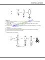
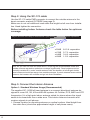
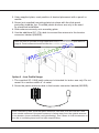
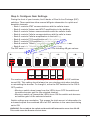
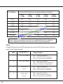
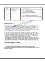
Force5-50
2G-3G-4G 5-Band Wireless
Adjustable Cellular Booster Kit
Introduction
Theory of Operation
Packages Contents
Booster Hardware
Introduction
Theory of Operation
Installation
Quick Install Guide
Configuring Gain Setting
Installation Steps
Troubleshooting
Safety Information
User Guide
INTRODUCTION
Thank you for your purchase of the Force5-50. The Force5-50 5-Band
adjustable cellular signal booster removes the frustration over dropped calls,
limited range and slow data rates by amplifying incoming and outgoing cellular signals in large watercraft. The Force5-50 enhances 2G, 3G and 4G data
reception data for all major US. Carriers.
This guide contains all the information you’ll need to get your Force5-50
booster system up and running. If you need any assistance while installing
this product please contact tech support at 1-888-365-6283 or email us at:
[email protected].
BEFORE USE, you MUST REGISTER THIS DEVICE with your wireless
provider and have your provider’s consent. Most wireless providers
consent to the use of this device on their network. If you are unsure,
contact your provider.
How it works
The Force5-50 is a high-quality bidirectional signal booster that enhances
signals to areas that are prone to weak cellular coverage.
Force5-50 works with two or more antennas:
• up to four inside antennas that communicate with your cellphone.
• an outside antenna that communicates with cellular towers.
Signals sent from a cellular tower are received by the outside antenna, amplified by the booster and then broadcast to your phone via the inside antenna.
When your phone transmits, the signal is sent to the inside antenna, amplified
and then sent to the cell tower via the outside antenna.
The signal booster requires a minimum cellular signal of low -100 dBm to high
-90 dBm. Signal readings usually appear as a negative number. The stronger
the signal, the closer it gets to zero. Signals stronger than -50dB may cause
the booster to temporarily shut down.
To measure your existing cellular signal on an Apple iPhone, dial
*3001#12345# and press Call. In the top-left corner, your dB number appears
instead of bars.
For Android devices, you can download several apps to measure exact signal
strength. In your phone’s App Store, search for “check signal strength” to find
a cell signal measurement app.
2
INTRODUCTION
Package Contents:
Unpack all package contents, compare them against the package contents
list, and check for damage. For missing or damaged items, contact your
retailer. Keep the carton and packing material to store the product or if you
need to return it.
Booster
Outside Antenna
with mount
Inside Antenna
with bracket
Cable-20’ and 40’
Phantom Package Contents
50 dB adjustable booster
(2) SC174 10 foot cables
SC-110W inside antenna
SC-200 outside antenna
248W-M inside panel antenna
18V DC power supply
Screws not supplied* Please purchase separately.
The following image shows the key hardware components on the cellular
booster. Refer to this image as you install your Force5-50 components.
Mount Kit
N connector to outside antenna
Power Switch
Power Jack
Power LED
Alert LED
N connector to inside antenna
Programmer
3
INSTALLATION
Quick Install Guide
Installation
The Force5-50 booster kit is specially designed for marine applications. It can
also be used for other applications with the right antennas, cables and mounting
hardware.
Step 1. Connect the SC-200 Outside Antenna
The SC-200 is a, full-band antenna, ideal for marine use.
Option 1 (Recommended)
1. Choose a mounting location that is as high as possible, free from obstructions
and as far as possible from other antennas and sources of RF signal.
2. Before mounting base, drill a hole in the middle of the mounting location wide
enough in diameter to allow SC-174 cable with FME connector to go through.
3. Hand-tighten the antenna base to the ferrule.
4. Feed cable, N connector end first, through bottom of base and through
hollowferrule.
5. Hand-tighten N connector to outside antenna and antenna to ferrule.
6. Feed cable, FME end first through the drilled hole.
7. Mount base (screws not provided) and hand tighten ferrule to mount base.
4
INSTALLATION
N connector
2
1
2
1
1
Option 2
1. When location of outside antenna has been determined, remove cap from
ferrule side hole.
2. Feed FME connector (small end) and cable through side hole on the f
shown in the figure below.
3. Feed remainder of cable through ferrule hole until approximately 1” of cable
remains.
4. Connect N connector to antenna.
5. Screw antenna onto ferrule, bend cable to prevent cable from twisting.
6. Screw base onto other end of ferrule.
7. Mount base onto location.
2
N connector
1
3
FME connector
5
Step 2. Using the SC-174 cable
Use the SC-174 cable FME connector to connect the outside antenna to the
boost connector marked OUTSIDE (see page 3).
Make sure to not coil additional coax cable that might be left over from installation. Hand tighten the connection.
Before installing Indoor Antenna check the table below for optimum
coverage.
Adjust dB Gain according to table below if you cannot achieve maximum separation.
Required Between
Outside and Inside Antenna
nn
nte
a
tion
ara
ep
as
• 50dB
• 47dB
• 44dB
• 40dB
8-10 ft. separation
5-7 ft. separation
3-4 ft. separation
1-2 ft. separation
Note: As you can see from the table above, acquiring the recommended inside and
outside antenna separation optimizes coverage significantly. Panel antenna can be
vertically installed 6 ft. under outside antenna with the booster at full dB gain.Inside
panel antenna should face away from outside antenna. If panel antenna faces outside
antenna, the booster will oscillate and go into Auto Shutdown.
Step 3. Connect the Interior Antenna
Option 1: Standard Wireless Usage (Recommended)
The supplied SC-110W full-band antenna is a compact directional antenna designed to cover 2G, 3G, 4G and WLAN systems for Cellular, PCS, AWS and LTE
frequencies. It’s a high-gain indoor antenna suited for places where the signal
needs to be broadcast over a wide area. This interior antenna transmits and
receives signals to cell phones.
1. Choose location for mounting antenna on vertical surface. Ideal height from
the cabin floor (should be approximate height of cell phone users).
6
2. Using supplied plate, mark position of desired placement with a pencil or
marker.
3. Screw (not supplied) mounting plate into place with the slide panel
protruding towards you. Provided plastic anchors are only to be used
for sheetrock installation.
4. Slide antenna securely onto mounting plate.
5. Use the additional SC-174 cable to connect the antenna to the booster
connector labeled (INSIDE).
Note: Be sure to provide enough separation from outside antenna (see table on
page 6. Panel antenna should not face the outside antenna.
Option 2 : Low Profile Usage
1. The supplied SC-110W patch antenna is intended for indoor use only. Do not
mount on a surface within 4” of metal.
2. Screw the patch antenna cable to the booster connector labeled (INSIDE).
Note: Laboratory tests show that patch antennas can work from as close as 2 feet
from outside antennas if the patch antenna is facing away from the outside antenna.
If the booster shows oscillation (red light blinking), turn it down in 3 dB increments on
the dial of oscillating band until the light stops blinking.
7
Step 4. Install the Signal Booster
1. Select a location close to a working AC outlet. Do not expose the signal
booster to excessive heat, direct sunlight, moisture, and airtight enclosures.
2. If you’d like to mount the booster to a wall, mark location of screw tabs on
the wall in the desired location
3. Use supplied screws or appropriate screws for surface of mounting location
and drill through screw tab holes on booster.
4. Ensure that the outside antenna cable is connected to the signal booster
connector marked OUTSIDE. Hand-tighten the connection.
5. Ensure that the inside antenna cable is connected to the signal booster
connector marked INSIDE. Hand-tighten the connection.
6. Connect the AC power cord to the signal booster.
7. Connect the plug on the other end of the 110V AC power outlet.
8. Turn the booster’s power switch on.
• The signal booster turns on automatically
• The Power LED lights up green to show that the signal booster is ready
to use.
• The Alert LEDs flash red and yellow intermittently on each band,
indicating that the band is activated.
Note: If the Power LED does not turn ON or the Alert LEDs continue to flash, see
Troubleshooting on page 12-13. This booster is rated for 19V AV input voltage. DO
NOT use the booster with a higher voltage power supply. This can damage the
booster and/or cause personal injury and void your warranty.
DIP Switches and Lights
The Force5-50 booster has the following indicators and controls:
•P
CS Uplink Warning light DIP switches. These DIP switches control the
PCS communications with the cellular tower.
•P
CS Downlink Warning light DIP switches. These DIP switches control
the PCS amplification within the building.
•P
ower Light: This light should be illuminated or blinking green at all times
while the booster’s power is on.
•C
ellular Uplink Warning light DIP switches. These DIP switches control
the cellular communications with the cellular tower.
•C
ellular Downlink Warning light DIP switches. These DIP switches control
the cellular amplification within the building.
8
Step 5. Configure Gain Settings
Facing the front of your booster, find 9 banks of Dual In-line Package (DIP)
switches. These switches allow manual dB gain attenuation for uplink and
downlink channels.
•B
ank 1 controls AT&T communications with the cellular tower.
• Bank 2 controls Verizon and AT&T amplification in the building.
• Bank 3 controls Verizon communications with the cellular tower
•B
ank 4 controls Cellular communications with the cellular tower.
• Bank 5 controls Cellular amplification in the building.
• Bank 6 controls PCS amplification with the cellular tower.
• Bank 7 controls PCS amplification in the building.
•B
ank 8 controls T-Mobile communications with the cellular tower.
• Bank 9 controls T-Mobile amplification in the building.
The DIP switches in each bank correspond to the following dB gain values:
LTE-707
LTE-781
Bank 1
ON
DIP
Bank 2
ON
DIP
Bank 3
ON
Cellular-800
Bank 4
DIP
ON
DIP
PCS-1900
Bank 5
ON
DIP
Bank 6
ON
DIP
AWS-2100
Bank 7
ON
DIP
Bank 8
ON
DIP
Bank 9
ON
DIP
1 2 3 45
1 2 3 45
1 2 3 45
1 2 3 45
1 2 3 45
1 2 3 45
1 2 3 45
1 2 3 45
1 2 3 45
1 2 4 8 16
LTE707-UL
1 2 4 8 16
LTE-DL
1 2 4 8 16
LTE781-UL
1 2 4 8 16
1 2 4 8 16
1 2 4 8 16
PCS-UL
1 2 4 8 16
PCS-DL
1 2 4 8 16
AWS-UL
1 2 4 8 16
AWS-DL
CELLULAR-UL
CELLULAR-DL
Switch1
Switch2
Switch3
Switch4
Switch5
1 dB
2 dB
4 dB
8 dB
16 dB
For maximum gain on all channels, your booster ships with all DIP switches
turned ON. This setting should always be your starting point when installing
or reinstalling the booster. To change it, move the DIP switches to the ON or
OFF position.
•M
oving a switch down (away from the LEDs) turns OFF the switch and
increases booster gain for the selected channel.
•M
oving a switch up (toward the LEDs) turns ON the switch and decreases booster gain for the selected channel.
Switch settings are cumulative. This means the total amount of attenuation for
a channel equals the combined dB of all DIP switches in the same bank being
set to ON.
WARNING: Do not adjust the uplink and downlink dB attenuation more than 20 dB.
This could cause the booster to shut down.
9
To Achieve...
Set the DIP Switchs in the Same Bank as Follows...
SW1
(1 dB)
SW2
(2 dB)
SW3
(4 dB)
SW4
(8 dB)
SW5
(16 dB)
0 DB
OFF
OFF
OFF
OFF
OFF
1 DB
ON
OFF
OFF
OFF
OFF
3 DB
ON
ON
OFF
OFF
OFF
7 DB
ON
ON
ON
OFF
OFF
15 DB
ON
ON
ON
ON
OFF
21 DB
ON
OFF
ON
OFF
ON
31 DB
ON
ON
ON
ON
ON
Note: As you see from the table above, attaining the recommended indoor and
outdoor antenna separation optimizes coverage significantly. Any reduced
antenna separation deceases the booster’s cellular signal capabilities.
LEDs
A Light-Emitting Diode (LED) appears above each DIP switch bank on the top
panel of the signal booster.
LED
10
Designation
Description
1
LTE 707 Uplink
OFF = normal operation.
ON = LTE AT&T uplink warning.
Power off booster immediately.
2
LTE 781 Uplink
OFF = normal operation.
ON = LTE Verizon uplink warning.
Power off booster immediately.
3
Cellular 800
Uplink
OFF = normal operation.
ON = Cellular uplink warning.
Power off booster immediately.
4
PCS 1900
Uplink
OFF = normal operation.
ON = PCS downlink warning.
Power off booster immediately.
LED
Designation
5
AWS 2100
Uplink
6
Power
Description
OFF = normal operation.
ON = AWS uplink warning.
Power off booster immediately.
Green ON or blink = booster receiving power.
OFF = booster not receiving power
Red ON = oscillation has occurred for longer
than 15 minutes and the booster is shutting
down
Automatic Shutdown
SureCall boosters that have automatic shutdown work in the following way:
1. The cellular side (LEDs 4 and 5) is usually the first side to experience
oscillation. When oscillation is detected in the uplink and/or downlink, the
appropriate red Warning LEDs flash and Power (LED 3) turns red.
2. If oscillation occurs on the PCS side, LEDs 1 and/or 2 blink as appropriate
and Power (LED 3) turns red due to cellular oscillation.
3. If the problem is not resolved, the affected side shuts down after 30 seconds. In general, the cellular side oscillates more easily than the PCS side.
4. The booster wakes up and Power (LED 3) turns green. If oscillation resumes, the LEDs flash as described previously. These 30-second cycles
continue for 15 minutes or until the problem is resolved.
5. If the problem is not resolved within 15 minutes, the booster shuts down
automatically (all LEDs OFF except Power, which is red) and must be reset
by unplugging the booster from the power supply and plugging it back in.
6. To resolve oscillation, increase antenna separation and/or the attenuation.
If you Want to Improve Coverage
•F
ind a location that receives a stronger signal and relocate the outside
antenna to that location.
• Increase the distance between the outside and inside antennas.
Be sure your signal booster’s dB gain is turned up to maximum gain on each
dial (see page 16).
11
Problem
Resolution
Signal booster has no power
Verify that the booster switch is turned on.
Connect the power supply to an alternate power source. Be sure
the AC outlet is working and is not controlled by a wall switch that
can cut power to the outlet. If the green POWER LED on the signal
booster is OFF, return the power supply to SureCall. Contact tech
support at 1-888- 365-6283 or [email protected], or go to
www.surecall.com and log on to online support to receive a Return
Merchandise Authorization (RMA).
After installing your signal booster system, you have no signal or
reception.
Check the strength of the outside signal as close as you can to the
outside antenna. (see instructions on page 7)
Double-check all signal booster and antenna cable connections.
Be sure your signal booster’s dB gain is turned up to full power on
each dial. (see apge 14)
LED flashing yellow
12
This means that the Automatic Gain Control (AGC) is adjusting
which is part of the boosters normal operation
One of the red LEDs next to
the dials on your signal
booster is flashing red.
Turn down the dB gain on the dial until the light goes OFF or turns
yellow.
Be sure the inside panel antenna is facing away from the outside
antenna.
Use the recommended antenna separation:
72dB: 100-110 ft. separation
65dB: 75-80 ft. separation
55dB: 60 ft. separation
50dB: 50 ft. separation
45dB: 15-20 ft. separation
40dB: 5-6 ft. separation
Your signal booster
restarted and shut down
for 15 minutes, and is now
shut down permanently.
Each SureCall signal booster is equipped with Auto Shutdown to
prevent cell tower interference. The outside antenna may be close
to a cell tower. Move the outside antenna to a location that provides
sufficient distance from the cell tower to prevent the signal booster
from automatically enabling Auto Shutdown. Once away from the
original location, perform the procedure under step 3 on page 10
The red LED goes ON.
More antenna separation is needed. If you cannot provide more
antenna separation and the Alert LEDs flash after the initial activation
period, lower the dial above the blinking LED by 5dB (for example,
from 50 to 45) and monitor the bars on your cell phone to see
whether reception improves.
The Power LED does not
turn ON
Be sure the AC outlet is working and is not controlled by a wall
switch that can cut power to the outlet.
Problem
Resolution
The Alert LEDs flash after the
initial activation period.
Lower the dial above the blinking LED by 5dB (for example, from
65 to 60) and monitor the bars on your cell phone to see whether
reception has improved.
The Alert LEDs continue
to flash
The singal booster shuts down automatically, and then restarts after
60 seconds. Turn down the Cellular, PCS or LTE/AWS dial that is
oscillating dial that is to prevent the signal booster from shutting
down autimatically.
Your signal booster has
no power.
Verify that the switch on the power supply is turned on and red LED is ON.
Connect the power supply to an alternate power source.
Be sure the power source is not controlled by a switch that can remove
power from the outlet.
Check the green POWER LED on the signal booster. If it is OFF, return the
power supply to SureCall. Contact tech support at
1-888-365-6283 or [email protected], or go to www.surecall.com
and log on to online support to receive an RMA.
Product Name
Force5-50
Uplink Frequency Range (MHz):
698-716 / 776 – 787 / 824-849
1850-1915 / 1710-1755 G Block Included
Downlink Frequency Range (MHz):
728-746 / 746 – 757 / 869-894
1930-1995 / 2110-2155 G Block Included
Input Impedance:
50 Ω
Maximum Gain:
50dB
Noise Figure:
8 dB
VSWR:
≤2.0
Supported Standards:
CDMA, WCDMA, GSM, EDGE, HSPA+, EVDO, LTE and all cellular standards
AC Input:
Input AC110V, 60 Hz; Output DC 19 V
Maximum Output Power:
1 Watt EIRP
Cable:
SC-400
RF Connectors:
N Female (both ends )
Power Consumption:
<50W
Operation Temperature:
-4ºF to +158ºF
Dimensions:
11.3” x 10.9” x 2.5”
Weight:
16.5 lbs
FCC (USA):
RSNFORCE-550
13
Vehicle Kitting
Component
Gain/Loss
Product Number/ Description
LTE-A
LTE-V 800 MHz 1900 MHz
Outdoor Antenna*
SC-200
3dBi
3dBi
Outdoor Cable
SC-174
3.8dB
3.8dB
Indoor Antenna
SC-110W (table top)
1.1dBi
1.1dBi
Indoor Cable
SC-174
3.8dB
3.8dB
4.3dB
3dBi
1700 MHz/2100 MHz
5dBi
5dBi/5dBi
4.3dB
8.8dB
6.98dB/8.96dB
1.1dBi
3dBi
3dBi/3dBi
8.8dB
6.98dBi/8.96dB
Marine Kitting
Component
Outdoor Antenna*
Gain/Loss
Product Number/ Description
SC-288W or Galaxy 5412-p
LTE-A
LTE-V
3dBi
3dBi
800 MHz 1900 MHz
3dBi
1700 MHz/2100 MHz
4dBi
4dBi/4dBi
Outdoor Cable
SC-240-40FN 40 Feet
3.52dB 3.52dB
3.98dB
6.52dB
6.12dB/6.92dB
Indoor Antenna
SC-248W
7dBi
7dBi
10dBi
10dBi/10dBi
Inside Cable
SC-240-20FN 20 Feet
2.06dB 2.06dB
2.06dB
3.56dB
3.36dBi/3.76dB
7dBi
Desktop/RV Kitting
Component
Outdoor Antenna
Gain/Loss
Product Number/ Description
SC-288W
LTE-A
LTE-V 800 MHz 1900 MHz
3dBi
3dBi
3dBi
1700 MHz/2100 MHz
4dBi
4dBi/4dBi
Outdoor Cable
SC-240-40FN
3.52dB 3.52dB
3.98dB
6.52dB
6.12dB/6.92dB
Inside Antenna
SC-120W
1.2dBi
1.2dBi
3dBi
3dBi/3dBi
1.2dBi
*All equivalent antennas and cables are suitable for use with the Force5-50 booster.
Warning: Unauthorized antennas, cables, and/or coupling devices are prohibited by
current FCC regulations. Please contact FCC for details: 1
Changes or modifications not expressly approved by SureCall could void the user’s
authority to operate the equipment.
14
Three-Year Product Warranty
SureCall warrants its products for three years from the date of purchase against defects in workmanship and/
or materials. Specifications are subject to change. The three-year warranty only applies to products meeting
the latest FCC Certification Guidelines stated on 2/20/2013 and going into effect April 30, 2014. A two-year
warranty applies to any products manufactured before May 1, 2014.
Products returned by customers must be in their original, un-modified condition, shipped in the original or
protective packaging with proof-of-purchase documentation enclosed, and a Return Merchandise Authorization
(RMA) number printed clearly on the outside of the shipping container.
Buyers may obtain an RMA number for warranty returns by calling the SureCall Return Department toll-free at
1-888-365-6283. Any returns received by SureCall without an RMA number clearly printed on the outside of
the shipping container will be returned to sender. In order to receive full credit for signal boosters, all accessories originally included in the signal booster box must be returned with the signal booster. (The Buyer does not
need to include accessories sold in addition to the signal booster, such as antennas or cables.)
This warranty does not apply to any product determined by SureCall to have been subjected to misuse, abuse,
neglect, or mishandling that alters or damages the product’s physical or electronic properties.
SureCall warrants to the Buyer that each of its products, when shipped, will be free from defects in material and
workmanship, and will perform in full accordance with applicable specifications. The limit of liability under this
warranty is, at SureCall’s option, to repair or replace any product or part thereof which was purchased up to
THREE YEARS after May 1, 2014 or TWO YEARS for products purchased before May 1, 2014, as determined by examination by SureCall, prove defective in material and/or workmanship. Warranty returns must first
be authorized in writing by SureCall. Disassembly of any SureCall product by anyone other than an authorized
representative of SureCall voids this warranty in its entirety. SureCall reserves the right to make changes in any
of its products without incurring any obligation to make the same changes on previously delivered products.
As a condition to the warranties provided for herein, the Buyer will prepay the shipping charges for all products
returned to SureCall for repair, and SureCall will pay the return shipping with the exception of products returned
from outside the United States, in which case the Buyer will pay the shipping charges.
The Buyer will pay the cost of inspecting and testing any goods returned under the warranty or otherwise, which
are found to meet the applicable specifications or which are not defective or not covered by this warranty.
Products sold by SureCall shall not be considered defective or non-conforming to the Buyer’s order if they satisfactorily fulfill the performance requirements that were published in the product specification literature, or in accordance with samples provided by SureCall. This warranty shall not apply to any products or parts thereof which
have been subject to accident, negligence, alteration, abuse, or misuse. SureCall makes no warranty whatsoever
in respect to accessories or parts not supplied by it.
15
Limitations of Warranty, Damages and Liability:
EXCEPT AS EXPRESSLY SET FORTH HEREIN, THERE ARE NO WARRANTIES, CONDITIONS, GUARANTEES, OR REPRESENTATIONS AS TO MERCHANTABILITY, FITNESS FOR A PARTICULAR PURPOSE, OR OTHER WARRANTIES, CONDITIONS, GUARANTEES, OR REPRESENTATIONS, WHETHER
EXPRESSED OR IMPLIED, IN LAW OR IN FACT, ORAL OR IN WRITING.
SURECALL AGGREGATE LIABILITY IN DAMAGES OR OTHERWISE SHALL NOT EXCEED THE PAYMENT,
IF ANY, RECEIVED BY CELLPHONE-MATE, INC. FOR THE UNIT OF PRODUCT OR SERVICE FURNISHED
OR TO BE FURNISHED, AS THE CASE MAY BE, WHICH IS THE SUBJECT OF CLAIM OR DISPUTE. IN
NO EVENT SHALL SURECALL BE LIABLE FOR INCIDENTAL, CONSEQUENTIAL, OR SPECIAL DAMAGES, HOWSOEVER CAUSED.
All matters regarding this warranty shall be interpreted in accordance with the laws of the State of California, and any
controversy that cannot be settled directly shall be settled by arbitration in California in accordance with the rules
then prevailing of the American Arbitration Association, and judgment upon the award rendered may be entered in
any court having jurisdiction thereof. If one or more provisions provided herein are held to be invalid or unenforceable under applicable law, then such provision shall be ineffective and excluded to the extent of such invalidity or
unenforceability without affecting in any way the remaining provisions hereof.
SAFETY INFORMATION
This is a CONSUMER device.
BEFORE USE, you MUST REGISTER THIS DEVICE with your wireless provider and have your provider’s consent.
Most wireless providers consent to the use of signal boosters. Some providers may not consent to the use of this
device on their network. If you are unsure,
contact your provider. You MUST operate this device with approved antennas and cables as specified by the
manufacturer. Antennas MUST be installed at least 20 cm (8 inches) from any person. You MUST cease operating
this device immediately if requested by the
FCC or a licensed wireless service provider.
WARNING: E911 location information may not be provided or may be inaccurate for calls served BY
USING THIS DEVICE.
48346 Milmont Drive
Fremont, California 94538
USA
888.365.6283
Fax: 510.996.7250
www.surecall.com
SureCall has made a good faith effort to ensure the accuracy of the information in this document and disclaims the
implied warranties of merchantability and fitness for a particular purpose and makes no express warranties, except
as may be stated in its written agreement with and for its customers.SureCall shall not be held liable to anyone for
any indirect, special or consequential damages due to omissions or errors. The information and specifications in
this document are subject to change without notice. © 2014. All Rights Reserved. All trademarks and registered
trademarks are the property of their respective owners.
16
Note: This equipment has been tested and found to comply with the limits for a Class B digital device, pursuant to part 15 of the FCC
Rules. These limits are designed to provide reasonable protection against harmful interference in a residential installation. This equipment
generates, uses and can radiate radio frequency energy and, if not installed and used in accordance with the instructions, may cause
harmful interference to radio communications. However, there is no guarantee that interference will not occur in a particular installation. If
this equipment does cause harmful interference to radio or television reception, which can be determined by turning the equipment off and
on, the user is encouraged to try to correct the interference by one or more of the following measures:
• Reorient or relocate the receiving antenna.
• Increase the separation between the equipment and receiver.
• Connect the equipment into an outlet on a circuit different from that to which the receiver is connected.
• Consult the dealer or an experienced radio/TV technician for help.
Safety Information
The Federal Communications Commision (FCC) has tested this product and found it to comply with their RF Exposure Requirements,
pursuant to FCC Part 22 and 24.
To comply with the FCC RF exposure requirement, keep the human user’s body at least 8” (20cm) from the indoor antenna of the booster.
Don’t expose this product to extreme low or high temperature (-4ºF or -20ºC and 150ºF or 70ºC).
There are no consumer serviceable or modifiable parts inside this booster product. Alteration or abuse of the booster other components will
void this product’s warranty, and could be dangerous to the user.
FCC 27.50(d)(4) Statement: Fixed, mobile and portable (hand-held) stations operating in the 1720-1755
MHz band are limited 1 Watt EIRP. Fixed stations operating in this band are limited to a maximum antenna height of 10 meters above ground. Mobile and portable stations operating in this band must employ a
means for limiting power to the minimum necessary for successful communications.
This is a CONSUMER device.
BEFORE USE, you MUST REGISTER THIS DEVICE with your wireless provider
and have your provider’s consent. Most wireless providers consent to the use of
signal boosters. Some providers may not consent to the use of this device on their
network. If you are unsure, contact your provider.
You MUST operate this device with approved antennas and cables as specified by
the manufacturer. Antennas MUST be installed at least 20 cm (8 inches) from any
person. You MUST cease operating this device immediately if requested by the
FCC or a licensed wireless service provider.
WARNING. E911 location information may not be provided or may be
inaccurate for calls served by using this device.
17