1
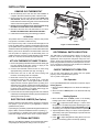
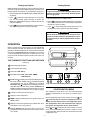
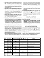
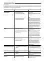
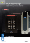
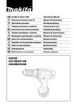
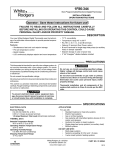
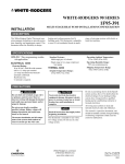
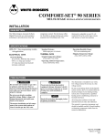
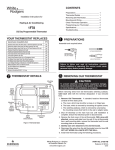
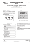
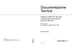
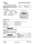
1F89-211
Non-programmable Electronic Digital
Heat Pump Thermostat
INSTALLATION AND
OPERATION INSTRUCTIONS
Operator: Save these instructions for future use!
FAILURE TO READ AND FOLLOW ALL INSTRUCTIONS CAREFULLY
BEFORE INSTALLING OR OPERATING THIS CONTROL COULD CAUSE
PERSONAL INJURY AND/OR PROPERTY DAMAGE.
DESCRIPTION
Your new White-Rodgers Digital Thermostat uses the
technology of a solid-state microcomputer to provide precise
temperature control.
Features:
• Simultaneous heat and cool setpoint storage
• Setpoint storage in case of power loss
• Pre-set temperature control
• LCD continuously displays setpoint and room temperature
•
•
•
•
Continuous Backlit display option
°F/°C convertibility
Temperature range 45° to 90°F
R, C, Y, W2, G, O/B, E, and L terminals for single or twotransformer systems
• Optional "AA" batteries to provide continuous temperature
display during loss of AC power
PRECAUTIONS
This thermostat is intended for use with a low voltage system; do
not use this thermostat with a line voltage system. If in doubt
about whether your wiring is millivolt, line, or low voltage, have
it inspected by a qualified heating and air conditioning contractor
or electrician.
Do not exceed the specification ratings.
All wiring must conform to local and national electrical codes and
ordinances.
This control is a precision instrument, and should be handled
carefully. Rough handling or distorting components could cause
the control to malfunction.
! CAUTION
!
WARNING
Do not use on circuits exceeding specified voltage.
Higher voltage will damage control and could cause
shock or fire hazard.
Do not short out terminals on gas valve or primary
control to test. Short or incorrect wiring will damage
thermostat and could cause personal injury and/or
property damage.
Thermostat installation and all components of the
system shall conform to Class II (current limited) circuits per the NEC code. Failure to do so could cause a
fire hazard.
To prevent electrical shock and/or equipment damage, disconnect electric power to system at main fuse
or circuit breaker box until installation is complete.
SPECIFICATIONS
ELECTRICAL DATA
APPLICATIONS
Electrical Rating:
20 to 30 VAC 50/60 Hz. or D.C.
0.05 to 1.0 Amps (Load per terminal)
1.5 Amps Maximum Total Load (All terminals combined)
For use with:
THERMAL DATA
Setpoint Temperature Range:
45°F to 90°F (7°C to 32°C)
Operating Ambient Temperature Range:
32°F to 105°F
Operating Humidity Range:
0 to 90% RH (non-condensing)
Shipping Temperature Range:
-4°F to 149°F
WHITE-RODGERS
EMERSON ELECTRIC CO.
9797 REAVIS ROAD
ST. LOUIS, MISSOURI 63123-5398
www.white-rodgers.com
• Standard heat pump systems with electric, gas or oil Aux
heat with 24 VAC HOT and COMMON available
• Single-stage heat pump systems with no Aux heat with
24 VAC HOT and COMMON available
DO NOT USE WITH:
• Millivolt systems
• Systems exceeding 30 VAC and 1.5 amps
• 3-wire zoned hydronic heating systems
Printed in U.S.A.
PART NO. 37-6233D
Replaces 37-6233C
0225
INSTALLATION
REMOVE OLD THERMOSTAT
Screw anchors
1. Shut off electricity at the main fuse box until installation is
complete. Ensure that electrical power is disconnected.
2. Remove the front cover of the old thermostat. With wires
still attached, remove wall plate from the wall. If the old
thermostat has a wall mounting plate, remove the thermostat
and the wall mounting plate as an assembly.
3. Identify each wire attached to the old thermostat using
the labels enclosed with the new thermostat.
4. Disconnect the wires from old thermostat one at a time.
DO NOT LET WIRES FALL BACK INTO THE WALL.
5. Install new thermostat using the following procedures.
O/B
switch
W904
Mounting
hole
Reset switch
(below Fan switch)
ATTENTION!
This product does not contain mercury. However, this product
may replace a unit which contains mercury.
Electric/Gas Mounting
jumper
hole
(W904)
Do not open mercury cells. If a cell becomes damaged, do not
touch any spilled mercury. Wearing nonabsorbent gloves, take
up the spilled mercury and place into a container which can be
sealed. If a cell becomes damaged, the unit should be discarded.
Figure 1. Thermostat Base
Mercury must not be discarded in household trash. When the
unit this product is replacing is to be discarded, place in a
suitable container and return to White-Rodgers at 9797 Reavis
Road, St. Louis, MO, 63123-5398 for proper disposal.
O/B TERMINAL SWITCH SELECTION
The O/B switch on this thermostat is factory set to the “O”
position. This will accommodate the majority of heat pump
applications, which require the changeover relay to be energized in COOL. If the thermostat you are replacing or the heat
pump being installed with this thermostat requires a “B” terminal, to energize the changeover relay in HEAT, the O/B switch
must be moved to the “B” position.
ATTACH THERMOSTAT BASE TO WALL
1. Remove the packing material from the thermostat. Gently pull
the cover straight off the base. Forcing or prying on the
thermostat will cause damage to the unit.
2. Connect wires beneath terminal screws on base using
appropriate wiring schematic (see figs. 2 through 4).
3. Place base over hole in wall and mark mounting hole
locations on wall using base as a template.
4. Move base out of the way. Drill mounting holes.
5. Fasten base loosely to wall, as shown in fig. 1, using two
mounting screws. Place a level against bottom of base,
adjust until level, and then tighten screws. (Leveling is for
appearance only and will not affect thermostat operation.) If
you are using existing mounting holes, or if holes drilled are
too large and do not allow you to tighten base snugly, use
plastic screw anchors to secure subbase.
6. Push excess wire into wall and plug hole with a fire-resistant
material (such as fiberglass insulation) to prevent drafts from
affecting thermostat operation.
CHECK THERMOSTAT OPERATION
If at any time during testing your system does not operate
properly, contact a qualified service person.
Turn on power to the system.
Fan Operation
If your system does not have a G terminal connection, skip to
Heating System.
1. Move fan switch to ON position. The blower should begin to
operate.
2. Move fan switch to AUTO position. The blower should stop
immediately.
Heating System
ELECTRIC/GAS JUMPER (Fan Option)
1. Move SYSTEM switch to HEAT position. If the auxiliary
heating system has a standing pilot, be sure to light it.
Read the following information before clipping the nonelectric
heat jumper. If you are unsure of your application, contact a
qualified service person.
If your emergency or auxiliary heat system requires that the
thermostat energize the fan circuit, do not cut jumper W904.
2. Press
to adjust thermostat setting to 1° above room
temperature. The Heat Pump system should begin to operate. However, if the Flame icon ( ) and Snowflake icon ( )
are flashing, the compressor lockout feature is operating.
3. Adjust temperature setting to 4° above room temperature.
The auxiliary heat system should begin to operate and tehe
Flame icon will be flashing.
OPTIONAL BATTERIES
4. Press
to adjust temperature setting below room temperature. The heating system should stop operating.
If your emergency or auxiliary system will energize the blower, then
jumper, W904, on the thermostat base must be cut (see fig. 1).
With two "AA" batteries installed, your thermostat will continuously display the temperature during a loss of AC power.
2
THERMOSTAT
O/B
Y
Changeover
Relay*
G
W2
E
See Note **
Fan
Relay
Compressor
Contactor
R
SYSTEM
SYSTEM
MONITOR
SWITCH
Emergency
Relay
Aux
Relay
(Stage 2)
L
C
Hot
24 VAC
120 VAC
Neutral
* Changeover Relay is energized in COOL when O/B switch is in the “O” position
Changeover Relay is energized in HEAT when O/B switch is in the “B” position
TRANSFORMER
(Class II current limiting)
** Jumper required to use a single Aux Heat for both Second Stage Heat and Emergency
Figure 2. Typical wiring diagram for single transformer systems
NOTE
If safety circuits are in
only one of the systems,
remove the transformer
of the system with NO
safety circuits.
THERMOSTAT
O/B
Y
G
W2
CUT AND
TAPE OFF!
Changeover
Relay*
HOT
24 VAC
120 VAC
NEUTRAL
E
See Note **
Fan
Relay
L
C
SYSTEM
MONITOR
SWITCH
Emergency
Relay
R
SYSTEM
Limit or
Safety
Switches
Aux
Relay
(Stage 2)
Compressor
Contactor
Hot
24 VAC
120 VAC
Neutral
TWO COMMONS MUST
BE JUMPERED TOGETHER!
* Changeover Relay is energized in COOL when O/B switch is in the “O” position
Changeover Relay is energized in HEAT when O/B switch is in the “B” position
TRANSFORMER
(Class II current limiting)
** Jumper required to use a single Aux Heat for both Second Stage Heat and Emergency
Figure 3. Typical wiring diagram for two transformer systems with NO safety circuits
NOTE
Polarity must be observed. If the HOT side of
the second transformer is jumpered to the
COMMON side of the first transformer a short
will be made. Damage to equipment will occur
when power is restored.
THERMOSTAT
O/B
Y
G
W2
E
L
C
R
SYSTEM
Limit or
Safety
Switches
See Note **
Changeover
Relay*
Compressor
Contactor
Fan
Relay
Emergency
Relay
SYSTEM
MONITOR
SWITCH
24 VAC
120 VAC
NEUTRAL
24 VAC
ACCESSORY
RELAY N.O.
CONTACT
Aux
Relay
(Stage 2)
COMMON
Auxiliary
Heating
Transformer
(Class II
current
limiting)
Limit or
Safety
Switches
TWO COMMONS MUST
BE JUMPERED TOGETHER!
* Changeover Relay is energized in COOL when O/B switch is in the “O” position
Changeover Relay is energized in HEAT when O/B switch is in the “B” position
Limit or
Safety
HOT
Switches
COMMON
NOTE
The accessory relay scheme
is required when safety
circuits exist in both systems.
Limit or
Safety
Switches
24 VAC
HOT
120 VAC
NEUTRAL
** Jumper required to use a single Aux Heat for both Second Stage Heat and Emergency
Heat Pump Transformer
(Class II current limiting)
Figure 4. Typical wiring diagram for two transformer systems with safety circuits in BOTH systems
3
Cooling System
Emergency System
EMER bypasses the Heat Pump to use the heat source wired to
terminal E on the thermostat. EMER is typically used when compressor operation is not desired, or you prefer back-up heat only.
1. Move SYSTEM switch to EMER position. EMER will flash on
the display.
! CAUTION
To prevent compressor and/or property damage, if the
outdoor temperature is below 50°F, DO NOT operate
the cooling system.
to adjust the thermostat above room tempera2. Press
ture. The Aux heating system will begin to operate. The
flame icon ( ) will display flashing to indicate that the Aux
system is operating
1. Move SYSTEM switch to COOL position.
to adjust thermostat setting below room tempera2. Press
ture. The blower should come on immediately on high speed,
followed by cold air circulation
to adjust the thermostat below room temperature.
3. Press
The Aux heating system should stop operating.
to adjust temperature setting above room tem3. Press
perature. The cooling system should stop operating.
! CAUTION
Do not allow the compressor to run unless the compressor oil heaters have been operational for 6 hours
and the system has not been operational for at least 5
minutes.
OPERATION
Before you begin using your thermostat, you should be familiar
with its features and with the display and the location and
operation of the thermostat buttons. Your thermostat consists of
two parts: the thermostat cover and the base. To remove the
cover, pull it straight out from the base. To replace the cover, line
up the cover with the base and press until the cover snaps onto
the base.
1
2
THE THERMOSTAT BUTTONS AND SWITCHES
FAN
OFF HEAT
(see fig. 5)
ON
AUTO
COOL
EMER
1 Raises temperature setting.
2 Lowers temperature setting.
4
3
3 FAN switch (ON, AUTO).
SA SU
4 SYSTEM switch (COOL, OFF, HEAT, EMER).
AM
PM
THE DISPLAY
FILTER
EMER
MALF
5 Flame icon ( ) is displayed when the SYSTEM switch is in
10
the HEAT position. Flame icon ( ) is displayed flashing
when 2nd-stage heat (Aux or Emergency) is energized.
Snowflake icon ( ) is displayed (non-flashing) when the
SYSTEM switch is in the COOL position. Snowflake and
Flame are displayed (flashing) if the thermostat is in lockout
mode to prevent the compressor from cycling too quickly.
8
9
5
8
7
6
5
Figure 5. Thermostat display, buttons, and switches
CONFIGURATION MENU
The configuration menu allows you to set certain thermostat
operating characteristics to your system or personal requirements.
6 Indicates a malfunction with the system.
7 Displays current temperature.
Move SYSTEM switch to the OFF position, then press
8 EMER is displayed flashing when the system switch is in
EMER position.
and
at the same time to enter the configuration menu. The
display will show the first item in the configuration menu.
9 Displays current set temperature (this is blank when SYSTEM switch is in the OFF position).
The configuration menu chart summarizes the configuration options. An explanation of each option follows.
10 Displays FILTER when the system has run for the programmed filter time period as a reminder to change or clean
your air filter.
Press
and
to change to the next menu item. To exit the
menu, move the SYSTEM switch to HEAT or COOL. If no keys
are pressed within fifteen minutes, the thermostat will exit the
configuration menu.
4
2) Select FA or SL (Fast or Slow) Heat Pump stage Cycle
Rate - The FA setting is used to produce shorter heating
cycles. The SL setting produces a longer heating/cooling
cycle. Both settings produce very accurate temperature
control and can be set to your personal preference. FA
cycles the system just under .75°F and the SL setting cycles
at approximately 1.2°F.
3) Select FA or SL (Fast or Slow) Auxiliary or Emergency
Cycle Rate - The FA setting is frequently used for gas, oil
or electric heat. The SL setting produces a longer heating
cycle. Both settings produce very accurate temperature
control and can be set to your personal preference. FA
cycles the system just under .6°F and the SL setting cycles
at approximately 1.°F.
4) Select backlit display (d-L OFF or ON) - The display
backlight improves display contrast in low lighting conditions. Selecting backlight ON will keep the light on continuously. Selecting OFF will keep the light off.
5) Select filter replacement run time - The thermostat will
display FILTER after a set time of operation. This is a
reminder to change or clean your air filter. This time can be
set from 0 to 1950 hours in 50 hour increments. A selection
of 000 will cancel this feature. When FLTR is displayed,
you can clear it by pressing
and
at the same time.
This resets the timer and starts counting the hours until the
next filter change. Contact your heat pump manufacturer for
a specific replacement/maintenance interval.
6) Select Compressor Lockout (LOC OFF or ON) - Selecting LOC ON will cause the thermostat to wait 5 minutes
before turning on the compressor if the heating and cooling
system loses power. It will also wait 5 minutes minimum
between cooling cycles. This is intended to help protect the
compressor from short cycling. Some newer compressors
already have a time delay built in and do not require this
feature. Your compressor manufacturer can tell you if the
feature is already present in their system. When the thermostat
compressor time delay occurs it will flash the Snowflake or
Flame icon for about five minutes.
7) Select Temperature Display Adjustment (4 LO to 4 HI) Allows you to adjust the room temperature display up to 4°
higher or lower. Your thermostat was accurately calibrated
at the factory but you have the option to change the display
temperature to match your previous thermostat. The current or adjusted room temperature will be displayed on the
right side of the display.
8) Select Temperature Display (°F or °C) - Changes the
display readout to Celsius or Fahrenheit as required. The
current room temperature will be displayed on the right side
of the display.
9) Select Fast second stage - In the RUN mode, if the
temperature is manually raised by 3°F (2°C) or more above
and the fast second stage
room temperature using
feature is enabled, FA on, the second stage will energize
immediately. With FA off, the second stage will not energize
until the setpoint temperature is 10°F or more above room
temperature.
OPERATING FEATURES
Now that you are familiar with the thermostat buttons and
display, read the following information to learn about the many
features of the thermostat.
• SIMULTANEOUS HEATING/COOLING SETPOINT
STORAGE — You can enter both your heating and cooling
setpoints at the same time. There is no need to change the
thermostat at the beginning of each season.
• CONFIGURATION MENU — Allows you to customize
certain thermostat options.
SETTING THE THERMOSTAT
This thermostat is very easy to operate. Set the SYSTEM switch
or
until the
to either HEAT or COOL then press
temperature you want to maintain is shown on the right side of
the display. If you want to turn the system off, just move the
SYSTEM switch to OFF.
The FAN switch controls the fan operation. When the FAN
switch is set to AUTO, the fan will cycle with the furnace or air
conditioner. When the FAN switch is set to ON, the fan will run
continuously, regardless of SYSTEM switch position.
Configuration Menu
Step
Press Button(s)
1
Set SYSTEM
switch to OFF
Displayed (Factory Default)
Press
or
FA
Select FA or SL (Fast or Slow) pump cycle rate
SL
Select FA or SL (Fast or Slow) Auxiliary and
Emergency Aux heating cycle rate
and
3
and
4
and
5
and
6
and
LOC
(OFF)
on
7
and
0 HI
(0)
4 LO to
4 HI
8
and
(F)
°C
9
and
FA
(on)
OFF
* Press
(SL)
EMER
(FA)
d-L
(on)
Filter
(000)
OFF
0 to 1950 hours
(in 50 hour increments)
Set SYSTEM switch
to HEAT or COOL
and
COMMENTS
SYSTEM switch must be OFF to configure thermostat options
2
10
to select:
to advance to next item
Select display backlight OFF or ON
Select filter replacement run time
Select Compressor lockout OFF or ON
Select temperature display adjustment higher or lower
Select temperature display to °F or °C
Select fast second-stage ON or OFF
Returns to normal operation
5
TROUBLESHOOTING
Reset Operation
If a voltage spike or static discharge blanks out the display or causes erratic thermostat operation you can reset the thermostat
by pressing the reset button (see fig.1) . If the thermostat has power, has been reset and still does not function correctly contact
your heating/cooling service person or place of purchase.
Symptom
Possible Cause
Corrective Action
No Heat/No Cool/No Fan
(common problems)
1. Blown fuse or tripped circuit breaker.
2. Furnace power switch to OFF.
3. Furnace blower compartment door or
panel loose or not properly installed.
Replace fuse or reset breaker.
Turn switch to ON.
Replace door panel in proper position to engage
safety interlock or door switch.
No Heat
1. System Switch not set to Heat.
Set System Switch to Heat and raise setpoint
above room temperature.
Verify thermostat and system wires are securely
attached.
Diagonistic: Set System Switch to Heat and raise
the setpoint above room temperature. Within a five
minutes the thermostat should make a soft click
sound. This sound usually indicates the thermostat
is operating properly. If the thermostat does not
click, try the reset operation listed above. If the
thermostat does not click after being reset contact
your heating and cooling service person or place
of purchase for a replacement. If the thermostat
clicks, contact the furnace manufacturer or a
service person to verify the heating system is
operating correctly.
2. Loose connection to thermostat or system.
3. Heating System requires service or
thermostat requires replacement.
No Cool
1. System Switch not set to Cool.
2. Loose connection to thermostat or system.
3. Cooling System requires service or thermostat
requires replacement.
Possible short in wiring.
Possible short in thermostat.
Possible short in Heat/Cool/Fan system.
Fan Switch set to Fan On.
Set System Switch to Cool and lower setpoint
below room temperature.
Verify thermostat and system wires are securely
attached.
Same procedure as diagnostic for No Heat
condition except set the thermostat to Cool and
lower the setpoint below the room temperature.
There may be up to a five minute delay before
the thermostat clicks in Cooling if the compressor
lock-out option is selected in the configuration
menu (Item 6).
Heat, Cool or Fan Runs Constantly.
1.
2.
3.
4.
Furnace Cycles Too Fast or Too Slow
(narrow or wide temperature swing)
1. The location of the thermostat and/or the size
of the Heating System may be influencing the
cycle rate.
Item 2 in the Configuration Menu is the adjustment
that controls the cycle rate. If an acceptable cycle
rate is not achieved using the FA (Fast) or SL
(Slow) adjustment contact a local service person for
additional suggestions.
Cooling Cycles Too Fast or Too Slow
(narrow or wide temperature swing)
1. The location of the thermostat and/or the size
of the Cooling System may be influencing the
cycle rate.
The cycle rate for cooling is fixed and can not be
adjusted. Contact a local service person for
suggestions.
Thermostat Setting and Thermometer
Disagree
1. Thermostat thermometer setting requires
adjustment.
The thermometer can be adjusted +/- 4 degrees as
listed in item 7 of the Configuration Menu. No other
adjustment is possible.
Blank Display and/or Keypad Not
Responding
1. Loss of power.
2. Voltage Spike or Static Discharge.
Check heat/cool system for power.
If a voltage spike or static discharge occurs use the
Reset Operation listed above.
6
Check each wire connection to verify they are
not shorted or touching together. No bare wire
should stick out from under terminal screws. Try
resetting the thermostat as described above.
If the condition persists, the manufacturer of
your system or service person can instruct you
on how to test the Heat/Cool system for correct
operation. If the system operates correctly,
replace the thermostat.