1
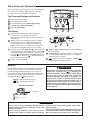
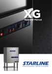
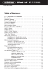
Emerson Blue Easy Set
1H/1C
Model: 1F86EZ-0251
Non-Programmable Thermostat with 3 Temperature Pre-Sets
Home, Sleep and Away
Installation Instructions and User Guide
Message to Homeowner
Congratulations on choosing the Emerson Blue Easy Set
Thermostat. The Easy Set is designed to be the easiest
thermostat you have ever used. This thermostat features
Home, Sleep, and Away temperature pre-sets. Just press
the button and go. Included with the easy set is the same
temperature accuracy and reliability you expect from all the
Emerson Blue thermostats.
3 Simple Pre-Sets
Just Press the Button and Go!
Table of Contents
Get to know your thermostat........................................2
Thermostat buttons and switches................................2
Display..........................................................................2
Batteries.......................................................................2
Using your thermostat..................................................3
Home, Sleep and Away temperature pre-sets.............3
Sleep Timer option.......................................................3
Change Filter reminder option.....................................3
Cool Savings option.....................................................3
Installation......................................................................4
Remove the old thermostat..........................................4
Install the new thermostat............................................4
Set switches.................................................................4
Check thermostat operation.........................................4
Select configuration options.........................................5
Configuration menu......................................................5
Troubleshooting Guide.................................................6
Technical Data................................................................7
Wiring diagrams...........................................................7
Thermostat application guide.......................................8
Specifications...............................................................8
This thermostat is intended for use with a low voltage NEC
Class II system. Do not use this thermostat with a line voltage
system. If in doubt about whether your wiring is millivolt, line,
or low voltage, have it inspected by a qualified heating and air
conditioning contractor or electrician.
Do not exceed the specification ratings.
All wiring must conform to local and national electrical codes
and ordinances.
This control is a precision instrument, and should be handled
carefully. Rough handling or distorting components could
cause the control to malfunction.
PART NO. 37-7201C
www.white-rodgers.com
www.emersonclimate.com
Replaces 37-7201B
1049
Get to know your thermostat
Figure 1. Thermostat buttons and switches
Before you begin using your thermostat, you should be familiar
with its features and with the display and the location and
operation of the thermostat buttons and switches.
Set at
1
Home
2
The Thermostat Buttons and Switches
1 Raises temperature setting.
2 Lowers temperature setting.
3 Easy Temperature pre-sets (Home, Sleep, Away).
SYSTEM
4 SYSTEM switch (COOL, OFF, HEAT).
5 FAN switch (ON, AUTO).
4
The Display
5
3
6 Indicates desired temperature. This is blank when
system switch is in the OFF position. Desired
temperature is displayed (flashing) if the thermostat is in
lockout mode.
7 “Save” indicates the Cool Savings feature is enabled
in the configuration menu. “Save” flashing indicates
Cool Savings feature is operating and saving energy.
“Save” will also flash for 3 seconds after changing the
temperature to indicate that a pre-set can be saved.
Set at
12
7
9
10
8
11
8 Indicates system mode. Heat icon ( ) is displayed when
10 “Home”, “Sleep”, “Away” indicates the easy temperature
the SYSTEM switch is in the HEAT position. Heat icon( )
is displayed flashing when thermostat is calling for heat.
Cool icon ( ) is displayed when the SYSTEM switch is in
the COOL position. Cool icon ( ) is displayed (flashing) if
the thermostat is calling for cool.
pre-set is enabled.
11 “Change Filter” is displayed when the system has run
for the programmed filter time period as a reminder to
change or clean your air filter.
12 “
” indicates power level of batteries. “Change
indicates batteries should be replaced.
9 Displays current temperature.
Batteries
! CAUTION
Two “AA” alkaline batteries are included with your thermostat.
Prior to use, open the battery door and remove the battery
tag. We recommend replacing batteries every 2 years, for
best results, use new premium brand alkaline batteries such
as Duracell® or Energizer®. When battery power remaining is
approximately half, the
will be displayed.
Change
6
Home Sleep
Away
If the home is going to be unoccupied for an extended
period (over 3 months) and
is displayed, the
batteries should be replaced before leaving. When
less than two months of battery life remain, the
setpoint temperature will change by 10 degrees (10
degrees cooler in Heat / 10 degrees warmer in Cool)
to alert you to change the batteries before they fail. If
the temperature change occurs, the normal setpoint
can be manually reset. However, the temperature will
change by 10 degrees within two days if the batteries
are not replaced.
Indicates batteries are low
and should be replaced
BATTERY LOCATION
“AA” Alkaline Batteries
!
WARNING
Do not use on circuits exceeding specified voltage.
Higher voltage will damage control and could cause
shock or fire hazard.
Do not short out terminals on gas valve or primary
control to test. Short or incorrect wiring will damage
thermostat and could cause personal injury and/or
property damage.
Thermostat installation and all components of the system
shall conform to Class II (current limited) circuits per the
NEC code. Failure to do so could cause a fire hazard.
2
”
Using your thermostat
Home, Sleep and Away Temperature
Pre-Sets
Change Home, Sleep and Away
Temperature Pre-sets
1. Move SYSTEM switch to HEAT position.
You can set your (Home, Sleep, Away) temperatures for use
when you get home, go to sleep, or leave home. Then, just
press the button you want and go.
2. Using the
or
button, set the desired temperature.
Favorite Temperatures are set at the factory as indicated in
the following table. You can use pre-sets or change to different
temperature pre-sets.
3. Press and hold the Home, Sleep, or Away button for 3
seconds. The display will go blank (except for the battery
icon and heat/cool icon) and back on again indicating that
the thermostat has saved your pre-set.
Factory Pre-set Temperatures
4. Repeat the process for the remaining Pre-sets to be
changed.
SLEEP
HEATING
COOLING
o
70 F
75o F
62o F
78o F
62o F
83o F
5. Move SYSTEM switch to COOL to Pre-set Temperatures
for cooling.
Use Home, Sleep and Away Temperature Pre-Sets
1. Press the Home, Sleep, or Away button. The display
will show the icon for the button pressed and display the
temperature setting.
Your Pre-set Temperatures
HEATING
2. The thermostat will maintain the selected pre-set
or
temperature until you change it by pressing the
button or selecting another Pre-set Temperature.
COOLING
SLEEP
Sleep Timer Option
The sleep timer will automatically change the thermostat from the Sleep to Home temperature after the number of hours set in
the configuration menu. The Sleep timer default is 8 hours and can be changed to a setting between 1 to 12 hours.
Example: You have selected 8 hours for the Sleep timer in the configuration menu. Press the Sleep button, the thermostat will
maintain the sleep temperature for 8 hours. After 8 hours the thermostat will go back to the Home temperature. The Sleep timer
will be activated each time the sleep button is pressed.
Change Filter Reminder Option
The thermostat can display a reminder when it is time to change the air filter on your heating and cooling system. The Change
Filter will automatically display after the number of hours set in the configuration menu. The change filter reminder time default
is 200 hours and can be changed to a setting of 25 to 1975 hours; 200 hours is approximately 3 months.
Example: You have selected 250 hours for the change filter reminder. The thermostat will display change filter after 250 it has
counted down 250 hours. When “Change Filter” is displayed, press the
or
button to clear the display and restart the
timer.
Cool Savings™ Option
With Cool Savings enabled, the thermostat will make small adjustments to the desired temperature during periods of high
demand to reduce cooling system running time and save energy. When the cooling system has been running for more than
20 minutes, humidity in the home will be lower and a higher temperature will feel comfortable. After 20 minutes of run time,
the thermostat will start increasing the desired temperature in steps of less than one degree as the system continues to run.
These adjustments will eventually cause the system to satisfy the thermostat and turn the system off to reduce the energy
consumption. When the Cool Savings feature is active and making adjustments, the display will flash “Save”. The amount of
adjustments to the desired temperature is dependent on the Cool Savings value that is set, 1 being the least adjustment and 6
being the most adjustment. With this feature set to OFF, no change will occur when the cooling system is continuously running
during the periods of high demand. Periods of high demand will normally occur during the late afternoon and early evening on
the hottest days of the summer.
3
Installation
Remove the Old Thermostat
Battery
Door
1. Turn off power to the heating and cooling system.
2. Remove the front cover of the old thermostat, this usually
pulls off.
3. Loosen the screws that hold the thermostat to the wall.
Mounting
Hole
4. Identify each wire attached to the old thermostat.
5. Disconnect the wires from old thermostat one at a time. DO
NOT LET WIRES FALL BACK INTO THE WALL.
Install the New Thermostat
Mounting
Hole
O/B
Switch
1. Open the battery door and detach the new thermostat
cover from the base.
2. With the base flush against the wall, mark mounting hole
locations on wall.
Gas/Elec
Switch
3. Move base out of the way and drill mounting holes.
Opening
for wires
Figure 1. Thermostat Base
4. Push wires through wire opening.
5. Position the base on the wall again and screw the mounting
screws into the wall anchors.
Set Switches
6. Connect each wire coming from the wall to its corresponding
terminal as shown in Fig. 2 thru 4 on page 7.
Gas / Elec Switch
If your system is a heat pump, the GAS/ELEC Switch must
be set to ELEC (see Fig. 1) If your system is a single stage,
the switch must be set to GAS. The switch setting must agree
with the system configuration selected in the configuration
menu.
Press down
G
Y
O/B Terminal Switch Selection
W
Insert
Wire
O/B
The O/B switch on this thermostat is factory set to the “O”
position. This will accommodate the majority of heat pump
applications, which require the changeover relay to be
energized in COOL. If the thermostat you are replacing or the
heat pump being installed with this thermostat requires a “B”
terminal, to energize the changeover relay in HEAT, the O/B
switch must be moved to the “B” position.
C
R
Wire Terminal Block
NOTE
Wires will not be connected to all terminals of the terminal
block.
Check Thermostat Operation
2. Move fan switch to ON position. The blower should begin
to operate.
Heating System
3. Move fan switch to AUTO position. The blower should stop
immediately.
1. Move SYSTEM switch to HEAT position. If the heating
system has a standing pilot, be sure to light it.
Cooling System
2. Press
to adjust thermostat setting to 1° above room
temperature. The heating system should begin to operate.
1. Move SYSTEM switch to COOL position.
3. Press
to adjust temperature setting below room
temperature. The heating system should stop operating.
2. Press
to adjust thermostat setting below room
temperature. The blower should come on immediately on
high speed, followed by cold air circulation. However, if the
setpoint temperature is flashing, the compressor lockout
feature is operating (see Configuration menu, item 5).
Fan Operation
If your system does not have a G terminal connection, skip to
Heating System.
to adjust temperature setting above room
3. Press
temperature. The cooling system should stop operating.
1. Move SYSTEM switch to OFF position.
4
Installation
Select Configuration Options
The configuration menu allows you to set certain thermostat operating characteristics to your system or personal requirements.
Enter Menu
SYSTEM
Set at
Home
Menu Navigation
Press
and hold
for 3 seconds
Press
for next. Press
to go back
Configuration Menu
Menu Screen
Number
Displayed
(Factory Default)
Press
or
to select options
01
(SS)
HP
Select Single Stage (SS) or
Heat Pump (HP) for a single compressor
02
Sleep
(OFF)
On
Select Sleep Timer On or OFF
If selected OFF, skip to menu screen 04
03
h
(8)
1 to 12
Select 1 to 12 hours for Sleep Timer On.
See Sleep Timer section on page 3
04
CS
(OFF)
On
Select Cool Savings Feature On or OFF
If selected OFF, skip to menu screen 06
05
CS
(3)
1 to 6
Select 1 to 6 for Cool Savings Feature On
See Cool Savings section on page 3
FA, SL
Select Adjustable Anticipation, cycle rate for Heat
See table below
FA, SL
Select Adjustable Anticipation, cycle rate for Cool
See table below
06
CR
(ME)
07
CR
(ME)
08
CL
(OFF)
On
09
L
(On)
OFF
10
Room Temp
(0)
4 LO to
4 HI
11
F
o
o
Select Compressor Lockout OFF or On. When selected On,
the thermostat will wait 5 minutes before turning the
compressor on.
Select Display Light On of OFF. When selected On and the “C”
terminal is connected, the backlight will stay on continuously.
When OFF the backlight will come on for a short time when any
key is pressed.
Select room temperature display for 4o higher or 4o lower than
the actual temperature
C
12
Change Filter
(OFF)
On
13
Change Filter
(200 h)
25 to 1975
Select oF or oC Display (temperature displayed in Fahrenheit or
Celsius)
Select filter maintenance indicator OFF or On.
If selected OFF, item B will be skipped
Select 25 to 1975 hours for Change Filter reminder
See Change Filter reminder section on page 3
To exit the menu: Set the system switch to Cool or Heat. If
no keys are pressed within fifteen minutes, the thermostat will
revert to normal operation.
Select Cycle Rate – The cycle rate can be adjusted to keep
the heat or cool on longer or shorter to match the temperature
response of the home with your heating and cooling system.
5
MODE
Fast
(FA)
Medium
(ME)
Slow
(SL)
SS Heat
0.6oF
0.8oF
1.2oF
SS Cool
1.2oF
1.7oF
HP Heat & Cool
1.2 F
1.7oF
o
Troubleshooting
Reset Operation
for approximately 10 seconds until the display goes blank. If
the thermostat has power, has been reset and still does not
function correctly contact your heating/cooling service person
or place of purchase.
If a voltage spike or static discharge blanks out the display
or causes erratic thermostat operation, you may need to
reset the thermostat. To reset, the System Switch must be
in Cool or Heat. Simultaneously press
and
buttons
Symptom
Possible Cause
Corrective Action
No Heat/No Cool/No Fan
common problems)
1. Blown fuse or tripped circuit breaker.
2. Furnace power switch to OFF.
3. Furnace blower compartment door or
panel loose or not properly installed.
1. Replace fuse or reset breaker.
2. Turn switch to ON.
3. Replace door panel in proper position to engage safety
interlock or door switch.
No Heat
1. System Switch not set to Heat.
1. Set System Switch to Heat and raise setpoint above
room temperature.
2. Verify thermostat and system wires are securely
attached.
3. Diagnostic: Set System Switch to Heat and raise
the setpoint above room temperature. Within a five
minutes the thermostat should make a soft click
sound. This sound usually indicates the thermostat
is operating properly. If the thermostat does not click,
try the reset operation listed above. If the thermostat
does not click after being reset contact your heating
and cooling service person or place of purchase for
a replacement. If the thermostat clicks, contact the
furnace manufacturer or a service person to verify the
heating system is operating correctly.
2. Loose connection to thermostat or
system
3. Heating System requires service or
thermostat requires replacement.
No Cool
1. System Switch not set to Cool.
2. Loose connection to thermostat or
system.
3. Cooling System requires service or
thermostat requires replacement
1. Set System Switch to Cool and lower setpoint below
room temperature.
2. Verify thermostat and system wires are securely
attached.
3. Same procedures as diagnostic for No Heat condition
except set the thermostat to Cool and lower the
setpoint below the room temperature. There may be up
to a five minute delay before the thermostat clicks in
Cooling if the compressor lock-out option is selected in
the configuration menu (Item 6).
Heat, Cool or Fan Runs
Constantly
1. Possible short in wiring.
2. Possible short in thermostat.
3. Possible short in Heat/Cool/Fan
system.
4. Fan Switch set to Fan On.
Check each wire connection to verify they are not
shorted or touching together. No bare wire should
stick out from under terminal screws. Try resetting the
thermostat as described above. If the condition persists,
the manufacturer of your system or service person
can instruct you on how to test the Heat/Cool/ system
for correct operation. If the system operates correctly,
replace the thermostat.
Furnace Cycles Too Fast
or Too Slow / Cooling
Cycles Too Fast or Too
Slow (narrow or wide
temperature swing)
1. The location of the thermostat and/or
the size of the Heating or Cooling
System may be influencing the cycle
rate.
Item 4 (CR Heat) or 5 (CR Cool) in the Configuration
Menu is the adjustment that controls the cycle rate. If an
acceptable cycle rate is not achieved using the FA (Fast)
or SL (Slow) adjustment contact a local service person
for additional suggestions.
Thermostat Setting and
Thermometer Disagree
1. Thermostat thermometer setting
requires adjustment.
The thermometer can be adjusted +/- degrees as listed in
item 8 of the Configuration Menu (see page 5). No other
adjustment is possible.
Blank Display and/or
Keypad Not Responding
1. Voltage Spike or Static Discharge.
If a voltage spike or static discharge occurs use the Reset
Operation listed above.
6
Technical Data
FigureFigure
2. Typical
wiring diagram
for single
transformer
single stage
systems
2. Typical
wiring diagram
for
single transformer
single
stage systems
Optional Jumper
for Jumper for
Optional
Single Stage
Heat Pump
Single
Stage Heat Pump
THERMOSTAT
O/B
Y
O/B
G
Y
Changeover
Relay*Changeover
Compressor
G
Fan
Relay
Relay*
W
W
C
C
Optional
Fan
Heat Relay
Relay
Heat Relay
Compressor
Contactor
Contactor
R
THERMOSTAT
R
SYSTEM
SYSTEM
Optional
Hot
24 VAC
Hot
120 VAC
24Neutral
VAC
* Changeover Relay is energized in COOL when O/B switch is in the “O” position
Changeover Relay is energized in HEAT when O/B switch is in the “B” position
120 VAC
Neutral
TRANSFORMER
* Changeover Relay is energized in COOL when O/B switch is in the “O” position
Changeover Relay is energized in HEAT when O/B switch is in the “B” position
(Class II Current Limited)
TRANSFORMER
(Class II Current Limited)
Figure
3. Typical
wiring
diagram
for two
transformer
single
stage
systems
NO safety
circuits
Figure
3. Typical
wiring
diagram
for two
transformer
single
stage
systems
withwith
NO safety
circuits
NOTE
NOTE
If safety
onlyofone of
If safety
circuitscircuits
are inare
onlyin one
the systems,
remove
the transformer
the systems,
remove
the transformer
the system
with
NO safety
circuits.
of the of
system
with NO
safety
circuits.
Optional
Jumper
for
Optional
Jumper
for
Heat Pump
SingleSingle
Stage Stage
Heat Pump
CUT CUT
ANDAND
TAPETAPE
OFF!OFF!
HOT
HOT
120 VAC120 VAC
O/B
O/B
Y
Y
Changeover
Changeover
Relay*Relay*
24 VAC 24 VAC
G
W
W
C
Fan Fan
RelayRelay
Compressor
Compressor
Contactor
Contactor
NEUTRAL
NEUTRAL
G
THERMOSTAT
THERMOSTAT
C
R
R
SYSTEM
SYSTEM
Limit or
Limit or
SafetySafety
Switches
Switches
Optional
Optional
Heat Relay
Heat Relay
Hot
24 VAC24 VAC
TWO COMMONS
TWO COMMONS
MUST MUST
* Changeover
Relay
is energized
in COOL
when
O/B switch
is “O”
in the
“O” position
BE JUMPERED
TOGETHER!
* Changeover
Relay is
energized
in COOL
when O/B
switch
is in the
position
BE JUMPERED
TOGETHER!
Changeover
Relay
is
energized
in
HEAT
when
O/B
switch
is
in
the
“B”
position
Changeover Relay is energized in HEAT when O/B switch is in the “B” position
Hot
120 VAC
120 VAC
Neutral
Neutral
TRANSFORMER
TRANSFORMER
II Current
Limited)
(Class(Class
II Current
Limited)
Figure
4. Typical
wiring
diagram
systemswith
withsafety
safetycircuits
circuitsininBOTH
BOTH
systems
Figure
4. Typical
wiring
diagramfor
fortwo
twotransformer
transformer single
single stage systems
systems
NOTE
NOTE
Polarity
side
of of
thethe
Polarity must
must be
beobserved.
observed.If IfthetheHOT
HOT
side
second
to to
thethe
COMMON
side
secondtransformer
transformerisisjumpered
jumpered
COMMON
side
of
bebe
made.
Damage
of the
the first
firsttransformer
transformera ashort
shortwillwill
made.
Damage
to
power
is restored.
to equipment
equipmentwill
willoccur
occurwhen
when
power
is restored.
Optional
Jumper
Optional
Jumper
forfor
Single
Stage
Heat
Pump
Single
Stage
Heat
Pump
O/B
O/B
Y
Y
Changeover
Changeover
Relay*
Relay*
Compressor
Compressor
Contactor
Contactor
G
G
W
W
Fan
Fan
Relay
Relay
C
C
THERMOSTAT
THERMOSTAT
R
R
SYSTEM
SYSTEM
Limit or
Limit
Safetyor
24 VAC
Safety
Switches
Switches 24 VAC
Optional
Optional
Limit or
Limit or
Safety
Safety HOTHOT
Switches
Switches
120 VAC
120 VAC
NEUTRAL
NEUTRAL
24 VAC
Auxiliary
24 VAC
Auxiliary
NOTE
ACCESSORY
Heating
NOTE
ACCESSORY
Heating The accessory
RELAY N.O.
Transformer
relay scheme
RELAY
N.O.
CONTACT
Transformer
(Class II
accessory
relaysafety
scheme
is The
required
when
Limited)
CONTACT Current
(Class
II
is required
safety
circuits
exist in bothwhen
systems.
Current Limited)
COMMON
Heat
Heat
Relay
Relay
circuits exist in both systems.
COMMON
TWO COMMONS MUST
BE COMMONS
JUMPERED TOGETHER!
TWO
MUST
BE JUMPERED TOGETHER!
COMMON
COMMON
* Changeover Relay is energized in COOL when O/B switch is in the “O” position
Changeover Relay is energized in HEAT when O/B switch is in the “B” position
* Changeover Relay is energized in COOL when O/B switch is in the “O” position
Changeover Relay is energized in HEAT when O/B switch is in the “B” position
Limit or
Safetyor
Limit
Switches
Safety
Switches 24 VAC
24 VAC
Limit or
Safety
Limit or
Switches
Safety HOT
Switches HOT
120 VAC
120 VAC
Heat Pump Transformer
(Class II Current Limited)
Heat Pump Transformer
(Class II Current Limited)
7
NEUTRAL
NEUTRAL
Technical Data
THERMOSTAT APPLICATION GUIDE
ATTENTION!
Thermostat
Configuration
Options
Thermostat
Applications
Maximum
Stages
Heat/Cool
Single Stage 1
No Heat Pump
(SS)
Gas, Oil, Electric, Heat
Only, Cool Only or Heat
/ Cool Systems
1/1
Heat Pump 1
Single Stage
Compressor Heat
Pump (HP)
Single Stage Compressor Heat Pump Systems
- with no Aux. Heat
1/1
This product does not contain mercury. However, this product
may replace a unit which contains mercury.
Do not open mercury cells. If a cell becomes damaged, do
not touch any spilled mercury. Wearing nonabsorbent gloves,
take up the spilled mercury and place into a container which
can be sealed. If a cell becomes damaged, the unit should be
discarded.
Mercury must not be discarded in household trash. When the
unit this product is replacing is to be discarded, place in a
suitable container. Refer to www.white-rodgers.com for location
to send the product containing mercury.
Specifications
Electrical Rating:
Battery Power......................................................
Input-Hardwire.....................................................
Terminal Load.............................................................
Setpoint Range...........................................................
Differential (Single Stage)...........................................
Differential (Heat Pump).............................................
Operating Ambient......................................................
Operating Humidity.....................................................
Shipping Temperature Range.....................................
Dimensions Thermostat..............................................
mV to 30 VAC, 50/60 Hz or DC
20 to 30 VAC
1.0 A per terminal, 1.5A maximum all terminals combined
45° to 90°F (7° to 32°C)
Heat 0.6°F; Cool 1.2°F (adjustable)
Heat 1.2°F; Cool 1.2°F (adjustable)
32° to +105°F (0° to +41°C)
90% non-condensing max.
-40° to +150°F (-40° to +65°C)
3-3/4” H x 4-3/4” W x 1-1/2” D
Homeowner Help Line: 1-800-284-2925
White-Rodgers is a division
of Emerson Electric Co.
The Emerson logo is a
trademark and service mark
of Emerson Electric Co.
www.white-rodgers.com
www.emersonclimate.com