1
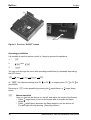
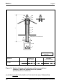
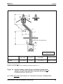
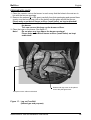
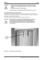
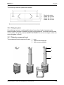
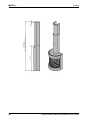
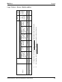
INSTALLATION INSTRUCTIONS AND INSTRUCTIONS FOR USE Wall-mounted gas fire with closed combustion system FREE BELL Bellfires wishes you many cosy evenings with your new Bellfires gas fire This document is an essential part of your gas fire. Read it carefully before installation and use of the gas fire and keep it in a safe place! Bellfires English BELLFIRES WALL-MOUNTED GAS FIRE WITH CLOSED COMBUSTION SYSTEM: FREE BELL Instructions for use and installation instructions 3 Bellfires 4 English Instructions for use and installation instructions Bellfires English CONTENTS Page 1. WARRANTY TERMS ................................................................................. 7 2. INSTRUCTIONS FOR USE ....................................................................... 9 3. INSTALLATION INSTRUCTIONS .............................................................. 20 4. MAINTENANCE ......................................................................................... 45 5. FAULTS ...................................................................................................... 46 6. ACCESSORIES ......................................................................................... 47 7. ELECTRICAL DIAGRAM ........................................................................... 48 8. DIMENSIONS ............................................................................................ 49 9. TECHNICAL DETAILS/REGULATIONS .................................................... 51 10. REPLACEMENT PARTS LIST .................................................................. 52 11. DISPOSAL OF PACKAGING AND APPLIANCE ....................................... 54 Instructions for use and installation instructions 5 Bellfires 6 English Instructions for use and installation instructions Bellfires 1 English WARRANTY TERMS Bellfires gas fire Warranty Bellfires guarantees the quality of the supplied hearth and the quality of the materials used. This warranty runs for a period of twelve (12) months from first use of the hearth and covers defects which are a result of construction faults or the failure of component parts. Bellfires has an obligation under the terms of this warranty (at its discretion) not to charge for the replacement of any component parts. ∇ - - Note: The following aspects are not covered under the terms of the warranty: defects arising which are attributable in whole or in part to: a Not paying due heed to installation, operating and maintenance instructions b Fitting/installation or repair by third parties (including the buyer) c Heat cracks arising in the jacket due to normal heating d Discolouration in the ironwork as a result of heat transfer the grate, the thermocouple and the glass of the product Should you wish to claim under the warranty, please contact your dealer. Please carefully retain your invoice with this warranty! Your Bellfires dealer: Date of installation: Bellfires Hallenstraat 17 NL-5531 AB Bladel Tel. + 31 497 339200 Fax. + 31 497 339210 Instructions for use and installation instructions 7 Bellfires 8 English Instructions for use and installation instructions Bellfires English 2 INSTRUCTIONS FOR USE 2.1 INTRODUCTION Congratulations on your purchase of this modern Bellfires wall-mounted gas fire. This quality product will provide you with many years of enjoyment due to the flame effect and warmth that it provides. Please read the instructions for use carefully before using the appliance for the first time. Keep this booklet in a safe place. 2.2 BUILT-IN PROTECTION OF THE APPLIANCE The appliance is fully protected by means of a thermo-electric pilot light shut off in the event of a gas escape from the main burner. 2.2.1 Safety Do not place embers, vermiculite granules, wood logs or pebbles against the pilot light burner. Make sure that the pilot flame can burn at all times freely over the main burner. Only in this way is proper ignition of the main burner ensured. Ignoring these directions could lead to a dangerous situation. It is essential that the appliance, the complete concentric flue system and the outlet are cleaned and inspected annually by a recognised fitter/gas specialist. The safe operation of the appliance will thus remain guaranteed. See for additional instructions Chapter 4: Maintenance. If the pilot flame goes out for any reason, wait for 5 minutes before attempting to re-light it. The gas fire must never be used with the door open or the door glass removed. Never place flammable material on the ceramic log set. The filling of the main burner with embers, vermiculite granules, wood logs and pebbles may not under any circumstances be changed or added to. Do not place easily-flammable materials, such as nylon clothing or flammable liquids, in the vicinity of the gas fire. Instructions for use and installation instructions 9 Bellfires English Ensure at all times that children and other people who are not aware of the operation of the gas appliance are only in the vicinity of the appliance exclusively under supervision. Use a fireguard to protect the people and children mentioned above against possible burns. 2.3 OPERATION: REMOTE CONTROL 2.3.1 General Read these instructions carefully before lighting the fire! The appliance is opperated by radio remote control. This comprises a hand-held transmitter and a receiver. The receiver is part of the gas control block assembly. The receiver and the gas control block are behind the frame at the bottom of the appliance. The hand-held transmitter and receiver are powered by batteries. Hand-held transmitter : 1x 9V battery. Receiver : 4x 1.5V battery type LR6 or AA. Option: 6V adapter (230 VAC). Available from your fitter. Note: Hand-held transmitter and receiver are not interchangeable with previous models. 2.3.2 Hand-held transmitter The remote control works by radio signal. The hand-held transmitter is configured in the factory with a unique signal code. 10 Instructions for use and installation instructions Bellfires English Figure 1: Hand-held transmitter Set the display • Connect the batteries. By simultaneously pressing OFF and (small flame), can be switched from °F (and 12 hour clock) to °C (and 24 hour clock), or vice versa. • The display will automatically return to mode after some time, but you may immediately return to mode by pressing the OFF button. Set the current time • By simultaneously pressing (large flame) and (small flame), the display flashes. You are in SET mode. • While the screen is flashing, you can adjust the time. • Press (large flame) to set the hour and (small flame) to set the minute. • Wait or press OFF to return to mode. Important: Setting up signal code before using the appliance for the first time. Before the appliance can be used, the receiver must first learn the hand-held transmitter’s signal code. • Press the “RESET” button on the receiver, and keep this pressed until 2 audio signals are heard. See figure 2. Release the “RESET” button after the second (somewhat longer) audio signal. • Press, within 20 seconds, the (small flame) button on the hand-held transmitter, until a somewhat longer signal is heard. The signal code has now been set up on the receiver. You only need to set up the signal code once. It is not necessary when changing the batteries of the hand-held transmitter or receiver. Instructions for use and installation instructions 11 Bellfires English Figure 2: Receiver “RESET” button Operating possibilities It is possible to use the remote control in 3 ways to operate the appliance: 1 : 2 : 3 : and You can cycle through the menu with operating possibilities by repeatedly depressing the SET button. At the selected starting time (P1 also shown. Returning to button. or P2 is also possible by pressing the ) or stopping time (P1 or P2 ) is (small flame) or (large flame) Manual operation Here you can turn the burner on and off, and adjust the height of the flames. • Press (large flame) to turn on the burner and to increase the flame height. • Press (small flame) decrease the flame height to turn the burner off. The pilot light will keep burning. (Stand-by position) 12 Instructions for use and installation instructions Bellfires English • The appliance will automatically revert to stand-by if: ° the hand-held transmitter is outside the range of the receiver for more than 6 hours. the batteries in the hand-held transmitter are almost depleted. ° ° the batteries in the receiver are fully depleted. • When one of the buttons on the hand-held transmitter is pressed (except the SET button), the transmission symbol appears on the screen. The receiver confirms the transmission with an audio signal. Operating day temperature thermostat (Appliance is in the stand-by position and the pilot light is burning.) Automatic temperature regulation of the pre-set day temperature. The room temperature is measured and compared with the pre-set day temperature. The flame height is automatically regulated so as to reach the pre-set day temperature. Also see: Setting the desired temperature. Operating the night temperature thermostat (Appliance is in the stand-by position and the pilot light is burning.) Automatic temperature regulation of the pre-set night temperature. The room temperature is measured and compared with the pre-set night temperature. The flame height is automatically regulated so as to reach the pre-set night temperature. Also see: Setting the desired temperature. Timer operation (Appliance is in the stand-by position and the pilot light is burning.) Appliance functions automatically according to the two pre-set heating periods; P1 and P2. These heating periods repeat automatically every 24 hours. Also see: Programming the timer: P1 and P2. The appliance works thermostatically at the pre-set starting times P1 and P2 and the room temperature is automatically regulated to the pre-set day temperature . The appliance works thermostatically at the pre-set stopping times P1 and P2 and the room temperature is automatically regulated to the pre-set night temperature . In order to allow the appliance to regulate the temperature at night, the night temperature must be set to at least 5°C. If the setting is lowered to , the appliance will switch to stand-by at night. The appliance will automatically operate at the following day cycle . N.B.: The pre-set temperature is shown on the screen every 30 seconds. Instructions for use and installation instructions 13 Bellfires English Setting the desired temperature by pressing the SET button • Select the desired mode of operation or briefly. • Hold the SET button until the display flashes. • Set the temperature with (large flame) or (small flame). • Wait or press the OFF button briefly to go to mode. • If the temperature control in should be off (lower battery consumption), decrease the night temperature until appears on the display. Important: Place the hand-held transmitter in a place that is not influenced by direct sunlight, draught, heat from the appliance and other heat sources. Programming the timer: P1 and P2 by pressing the SET button briefly. • Select the desired mode of operation • Press the SET button until P1 (heating period 1) and the time flashes. • Set the time for the beginning of the first heating period by pressing (large flame) for houre and (small flame) for minute’setting. • Press the SET button briefly; P1 appears on the display. Set the time for the end of the first heating period. • Press SET again to set the second heating period P2 (heat ON) and P2 (heat OFF). • Wait a moment or press OFF to switch back to mode. 2.3.3 Operation (Remote Control) Igniting the fire • Open the gas supply valve in the gas pipe to the fire. • Press the “O I” switch on the gas control block to the “I” position. • Turn the operating knob on the gas control block to the ON position. • Switch the hand-held transmitter to the position. • On the hand-held transmitter, press the «- OFF and (large flame) buttons simultaneously. A short tone will signal the start. Short beeps will then follow until the pilot light and main burner are ignited. Once the main burner has been ignited, the flame height will automatically rise to the maximum position. Important: • • • • 14 If the pilot flame goes out for any reason, wait for 5 minutes before attempting to re-light it. If the pilot light does not ignite after 3 ignition attempts; close the gas tap and warn the fitter. Once the pilot light is burning, the main burner must ignite within 10 seconds automatically. If this does not happen, immediately close the gas tap and warn the fitter. If the main burner ignites with a pop; immediately close the gas tap and warn the fitter. Instructions for use and installation instructions Bellfires English Connection Piezo Igniter (only for MANual control) ON/OFF Switch 8-wire Receiver Jack Microswitch Operating Knob Motor-Knob (in maximum position) Figure 3: Gas regulating block; Operating Knob in ON-position • Possible error messages: * 3x short audio signal, audible when the motor-knob operates: Receiver batteries need changing soon (having heard this signal, the appliance can be ignited another ten times approximately). * 5 second unbroken tone: Error. For example, one of the cables may not be properly connected, the “O I” switch is not in the “I” position. * 5 short beeps: Ignition of the pilot light and main burner failed. Possible cause: air in the pilot light pipe. Important: If the pilot flame goes out, then wait for at least 5 minutes before repeating the above procedure. Setting the flame height / extinguishing the fire • After ignition, the burner automatically sets the flames to the maximum height. • Press button (small flame) to lower the flames and to turn off the main burner (Extinguishing the fire: small flame button: pilot light remains burning!) (Pressing briefly the (small flame) button gradually lowers the flames to the low position.) • Press button (large flame) to increase the flame level and to turn on the burner. (Pressing briefly the (large flame) button gradually increases the flames to the high position.) Instructions for use and installation instructions 15 Bellfires Important: English • • If you turn on the main burner by pressing the (large flame) button, it must ignite within 10 seconds. If this does not happen, immediately close the gas tap and warn the fitter. If the main burner ignites with a pop; immediately close the gas tap and warn the fitter. Switching off the appliance • Press the (small flame) button to lower the flames or to switch off the main burner. • Then press the «-OFF button to switch off the appliance, including the pilot light. • Press the “O I” switch (on the gas control block) to the “O” position. This conserves battery life. • If the appliance is not to be used for some time, please close the gas supply valve in the gas pipe. Important: If the pilot flame goes out for any reason, wait for 5 minutes before attempting to re-light it. Faults • If the signals from the hand-held transmitter do not seem to be reaching the receiver, the cause may be: * Spent batteries: replace the batteries. * An electronic problem: press the “RESET” button on the receiver. • If the appliance regularly switches itself off, please contact your installer. Replacing the batteries • The hand-held transmitter/receiver batteries have a service life of approx. one year. We recommend you use alkaline batteries. • The batteries must be replaced whenever: 1 Hand-held transmitter: BATT appears in the display screen. 2 Receiver: 3x short audio signal, audible when the motor-knob operates. 1 Hand-held transmitter: * Open the cover on the back of the transmitter. * Carefully remove the 9V battery and disconnect it from the contact. Do not pull the wires! * Connect the new battery and replace in the battery compartment. Close the cover. 16 Instructions for use and installation instructions Bellfires English 2 * * * * Receiver: Carefully pull the receiver assembly out of the compartment. Open the cover. Remove the batteries from the battery compartment. Place four new 1.5V batteries (LR6 or AA type) as indicated in the battery compartment. The negative end (-) of the battery must always be at the contact spring end of the compartment. * Close the cover and place the receiver back in its holder. • If the batteries are inserted incorrectly, the electronics or drive may be irreparably damaged. • Only replace the batteries when the appliance has been completely switched off. 2.3.4 Operation (Hand control) In an emergency it is possible to operate the appliance manually. To do so, the ignition (piezo) cable must first be removed and transferred carefully to the piezo connector on the gas control block. Piezo button (only for MANual control) Connection Piezo Igniter (only for MANual control) Metallic Core for Manual Ignition (recessed switch) ON/OFF Switch 8 Wire Receiver Jack Microswitch Operating Knob (in Position for Manual Ignition) Motor-Knob (in maximum position) Figure 4: Gas regulating block; Operating Knob in MAN-position Instructions for use and installation instructions 17 Bellfires English Igniting the fire • Open the gas supply valve in the gas pipe to the fire. • Switch the “O I” switch on the gas regulating block to the “I” position. • Turn the motor-knob on the gas regulating block as far as it will go in a clockwise direction. The switch will audibly ‘click’. • Turn the operating knob on the gas control block to the MAN position. A recessed switch within the knob will become visible. • Press the recessed switch. Use a pen or similar instrument to do this. Gas will now flow to the pilot light. • While holding down the recessed switch, press the (square) piezo button several times (the piezo button is alongside the “O I” switch) to ignite the pilot light. Check whether the pilot light has been lit through the glass. • Once the pilot light is lit, the recessed switch must be kept down for a further ten seconds, after which it can be released. Important: If the pilot flame goes out, then wait for at least 5 minutes before repeating the above procedure. • Move the operating knob to the ON position. Depending on the position of the motorknob, the burner will either ignite or not. • By turning the motor-knob anti-clockwise to the desired position, the burner will ignite and the flame height can be controlled. Important: • When the main burner is switched on by turning the motor knob to the left, the burner must ignite within 10 seconds. If this does not happen, immediately close the gas tap and warn the fitter. • If the main burner ignites with a pop; immediately close the gas tap and warn the fitter. Extinguishing the fire • Turn the motor-knob on the gas regulating block as far as it will go in a clockwise direction. The knob will audibly ‘click’. The burner is now switched off. The pilot light will remain lit. Switching off the appliance • Press the “O I” switch on the gas regulating block to the “O” position. The pilot light will be extinguished. • If the gas fire is not going to be used for a long period of time, it is recommended to close the gas supply valve to the fire. Important: 18 If the pilot flame goes out for any reason, wait for 5 minutes before attempting to re-light it. Instructions for use and installation instructions Bellfires English 2.4 USING THE APPLIANCE FOR THE FIRST TIME The gas fire is coated with a lacquer layer resistant to high temperature. During the first hours of operation, the burning in of the lacquer may result in an unpleasant smell. This is harmless, however. Operating the gas fire at full capacity for a few hours, while ventilating the room, will eliminate the smell. After using your gas fire for the first few times, you may be aware of a light deposit on the inside off the glass. This is caused by the paint curing. Once your fireplace has cooled down, this deposit can be removed with glass cleaner or ceramic hob cleaner. 2.5 DAILY MAINTENANCE • Ensure that as little dust, and as few particles of cigarette smoke, candles and oil lamps as possible pollute the air in the room in which the appliance is used. Heating of these particles by the convection system of the appliance could lead to discoloration of the walls and ceiling. It is therefore very important to ensure that the room in which the appliance is located is sufficiently ventilated. Regularly remove any dust deposits from behind the frame by means of a vacuum cleaner. Important: If the glass is broken or cracked, it must be immediately replaced before operating the gas fire again. • If anything is spilt on the fire, switch it off immediately and wait for it to cool down sufficiently before cleaning. Never use scouring powder, aggressive cleaners or fire polish on the gas fire. Use only a dry lint free cloth. • Heat resistant lacquer in aerosols can be obtained from your distributor. During the yearly maintenance, the lacquer can be used to repair small areas of damage. IMPORTANT The installation must only be carried out by a CORGI registered installation engineer. Instructions for use and installation instructions 19 Bellfires 3 English INSTALLATION INSTRUCTIONS 3.1 GENERAL The gas fire must be positioned and connected as a “room sealed system” (balance flue) appliance by a CORGI registered gas installation engineer in accordance with the following installation instructions, nationally and locally applicable regulations (see “Technical Details/ Regulations” at the rear of this manual). If you have any queries regarding the installation, please consult your local gas company. Important: Before beginning the installation, check that the details on the rating plate correspond to the gas type and pressure to which the appliance will be connected. The appliance is factory set to the correct tolerances. The pilot light is set to the correct level of consumption. It is possible to install the gas fire with either a wall or roof outlet, using the Barbas concentric flue Ø100 mm (inner) - Ø150 mm (outer) system. The fumes are exhausted naturally to the outside environment through the inner Ø100 mm pipe whereas the combustion air supply passes between the Ø100 mm and Ø150 mm pipes. The gas fire can be installed in a completely sealed or mechanically ventilated house without extra ventilation and/or fume extraction. The appliance is a wall-mounted gas fire, which can only be installed on a wall constructed from non-flammable material. When handling the frame, we advise you to use the special gloves supplied, and to leave them with the owner of the hearth after installation. If an existing chimney is to be used, please consult your installer first. If the chimney was previously used for a wood or coal fire, then it should be cleaned by an expert. 3.2 BARBAS CONCENTRIC FLUE Ø100 MM - Ø150 MM SYSTEM The appliance is in combination with the concentric flue system [Ø100 mm – Ø150 mm] (either rigid or flexible) of Barbas compliant with the European CE norm for gas appliances, and may therefore only be used with this system. The guarantee is invalidated if the appliance is (completely or partially) installed using a different system. The Barbas concentric flue [Ø100 mm - Ø150 mm] system can be used with either a newly-built or existing chimney. 20 Instructions for use and installation instructions Bellfires English 3.3 PREPARATION FOR INSTALLATION The following preparation must be carried out before the gas fire can be installed. 3.3.1 Instructions for positioning the outlet 3.3.1.1 Positioning the outlet for correct operation: Roof-mounted outlet: >0.5 m Figure 5: Roof-mounted outlet This must be positioned at least 0.5 m from the roof edge; the apex of the roof can be disregarded. Wall-mounted outlet: >0.5 m Figure 6: Wall-mounted outlet This must be positioned at least 0.5 m from: • the corner of the building. • the roof overhang, the rain gutter. • balconies etc., unless the exhaust construction extends to at least the face of the protruding section. Instructions for use and installation instructions 21 Bellfires 3.3.1.2. English Positioning the outlet to avoid affecting the surrounding area All listed “distances” in this section are no more than guidelines. For the exact minimum “distances”, please consult your national and local directives. Distance” = minimum distance required for positioning of the outlet to avoid adverse effects with respect to: A. A ventilation opening serving an occupied room, a toilet or a bathroom. B. A heating air supply, when the supply flows through an occupied room. C. A window that can be opened and that is near an occupied room, a toilet or a bathroom. Roof-mounted outlet: To avoid adverse effects (*) Distance: outlet - A, B or C At the same roof level. >3 m (*) At a different roof level. >1 m (*) At a lower positioned wall. >1 m At a higher sloping surface. >3 m (**) If the required distance cannot be achieved, the outlet position rules take precedence. (**) If the required distance cannot be achieved, the position of the outlet must be at least 1 m above the highest facade/roof. 22 Instructions for use and installation instructions Bellfires English Wall-mounted outlet: To avoid adverse effects Distance: outlet - A, B or C At walls in buildings with staggered heights. Not permitted if A, B, or C are located above the outlet. On a wall - general. (*) Above the outlet: Below the outlet: Left and right of the outlet: At <1 m from the roof overhang. >2 m Beneath balconies, walkways etc. >2 m tot onderzijde van een uitstekend balkon of galerij. Beneath balconies, walkways etc. where the outlet extends to the front. >2 m To the garden or on the terrace. >2 m to the outside space. (**) With respect to a facing wall. >2 m (if the distance from the facing wall is less, the criteria detailed for “On a wall - general” apply). >2 m >0.75 m >0.75 m Enquire at your local gas company for the regulations relating to outlets positioned opposite each other and outlet(s) in facade(s) that form an angle. (*) These minimum distances do not apply if there is an obstruction between the outlet and A, B and C that protrudes at least 0.5 m from the wall and has a length exceeding the distance. (**) This distance is not required if the outlet is situated at least 1 m higher than the intended area of the outside space. If the outlet has a clearance of less than 0.5 m from the hard surface of a public area at a height of less than 2 m, it must be fitted with an effective protector. The mesh size of the guard must not affect the correct operation of the appliance. Instructions for use and installation instructions 23 Bellfires 3.4 English GENERAL SERVICES 3.4.1 The Fume Channel/Combustion Air Intake The combined fume channel and combustion air intake requires one of the following Barbas concentric flue system configurations. Important: Due to the high temperature of the outer walls (approx. 150°C), no flammable materials may be located or used in the vicinity of the flue system. After installation, encase the entire concentric flue system with a heat resistant material between the floor of the first storey and the outlet. Ventilate the covered concentric flue by fitting a grid near the floor and ceiling (on each floor). Do not insulate the concentric flue. Use the universal wall/floor support Ø150 mm to attach the covering of the concentric flue system [Ø100 mm - Ø150 mm], see 3.4.2, drawing number 36. 36 36 Use as a wall support Figure 7: 24 Use as a floor support Application universal wall/floor support Ø150 mm From the floor of the first storey as far as the vent Instructions for use and installation instructions Bellfires English RIGID CONCENTRIC FLUE Ø100 mm - Ø150 mm SYSTEM CONNECTION POSSIBILITIES X 19, 54 0.16 m 23 Wall Termination Position 10, 11, 12, 13, 50, 51, 52 Y 23 28, 56 4 1 Item descriptions: see 3.4.2 Appliance: Free Bell Distance Y (min.-max.) Distance X (min.-max.) 0.5 - 1.0 m 0 - 0.6 m - 1.0 - 3.0 m 0 - 2.0 m - Assemble restriction plate Figure 8: Horizontal wall termination ALL SIZES INCLUDE THE LENGTH OF THE ROOF OR WALL TERMINATION Instructions for use and installation instructions 25 Bellfires English 16 17 16 Y 18 24 23 28, 56 10, 11, 12, 13, 50, 51, 52 24 4 23 1 Item descriptions: see 3.4.2 Appliance: Free Bell Distance Y (min.-max.) Assemble restriction plate 2.0 - 8.0 m Width: B = 50 mm 8.0 - 12.0 m Width: B = 65 mm Figure 9: Vertical roof-mounted outlet without bend ALL SIZES INCLUDE THE LENGTH OF THE ROOF OR WALL TERMINATION 26 Instructions for use and installation instructions Bellfires English 16 17 Y2 24 23 X 23 14, 15, 53 10, 11, 12, 13, 50, 51, 52 23 Y1 28, 56 4 1 Item descriptions: see 3.4.2 Appliance: Free Bell Distance Y1 (*) Distance X (*) (min.-max.) (min.-max.) 1.0 - 10.0 m Distance Y1 + Y2 (*) (min.-max.) Assemble restriction plate 1.0 - 10.0 m Width: B = 30 mm 0 - 3.0 m (*) : (Y1 + Y2) : X > 2 : 1 (vertical to horizontal ratio (or 45° upwards) is always at least 2 to 1) Figure 10: Vertical roof-mounted outlet with bend ALL SIZES INCLUDE THE LENGTH OF THE ROOF OR WALL TERMINATION Instructions for use and installation instructions 27 Bellfires English FLEXIBLE CONCENTRIC FLUE Ø100 mm - Ø150 mm SYSTEM CONNECTION POSSIBILITIES 32 18 30 29 5 Y 7 29 26 25, 55 10, 11, 12, 13, 50, 51, 52 23 28, 56 4 1 Item descriptions: see 3.4.2 Appliance: Free Bell Distance Y (min.-max.) Assemble restriction plate 2.0 - 8.0 m Width: B = 50 mm 8.0 - 12.0 m Width: B = 65 mm Figure 11: Vertical chimney outlet using an existing lined chimney (Flexible Ø100 mm and/or rigid Ø100 mm / Ø150 mm) ALL SIZES INCLUDE THE LENGTH OF THE ROOF OR WALL TERMINATION 28 Instructions for use and installation instructions Bellfires English 32 18 30 29 Y3 Y2 > 45° 5 X 7 29 26 25, 55 Y1 10, 11, 12, 13, 50, 51, 52 23 28, 56 4 1 Item descriptions: see 3.4.2 Appliance: Free Bell Distance Y1 (*) Distance X (*) Distance Y1 + Y2 + Y3 (*) (min.-max.) (min.-max.) (min.-max.) 1.0 - 10.0 m 0 - 3.0 m 1.0 - 10.0 m Assemble restriction plate Width: B = 30 mm (*) : (Y1 + Y2+ Y3) : X > 2 : 1 (Vertical to horizontal ratio (or 45° upwards) is always at least 2 to 1) Figure 12: Vertical chimney outlet using a lined chimney with a bend > 45° (Flexible Ø100 mm and/or rigid Ø100 mm / Ø150 mm) ALL SIZES INCLUDE THE LENGTH OF THE ROOF OR WALL TERMINATION Instructions for use and installation instructions 29 Bellfires English 32 18 31 30 29 29 6 Y 8 7 Fitting the ornamental hood 27 28 29 26 29 4 1 Item descriptions: see 3.4.2 Appliance: Free Bell Distance Y (min.-max.) Assemble restriction plate 2.0 - 8.0 m Width: B = 50 mm 8.0 - 12.0 m Width: B = 65 mm Figure 13: Vertical chimney outlet using an existing unsound lined chimney or when no chimney liners are present (Flexible Ø100 mm / Ø150 mm) ALL SIZES INCLUDE THE LENGTH OF THE ROOF OR WALL TERMINATION 30 Instructions for use and installation instructions Bellfires English 32 18 31 29 30 29 Y3 Y2 6 > 45° 8 X 7 Y1 Fitting the ornamental hood 27 28 29 26 29 4 1 Item descriptions: see 3.4.2 Appliance: Free Bell Distance Y1 (*) Distance X (*) Distance Y1 + Y2 + Y3 (*) (min.-max.) (min.-max.) (min.-max.) 1.0 - 10.0 m 0 - 3.0 m 1.0 - 10.0 m Assemble restriction plate Width: B = 30 mm (*) : (Y1 + Y2+ Y3) : X > 2 : 1 (Vertical to horizontal ratio (or 45° upwards) is always at least 2 to 1) Figure 14: Vertical chimney outlet using an existing unsound lined chimney or when the chimney is unlined; with a bend >45o (Flexible Ø100 mm / Ø150 mm) ALL SIZES INCLUDE THE LENGTH OF THE ROOF OR WALL TERMINATION Instructions for use and installation instructions 31 Bellfires English 3.4.2 Item descriptions for figures 8 t/m 14. FIG. NO. DESCRIPTION 1 Wall-mounted gas fire; Free Bell 2 - 3 - 4 Restriction plate (Various restriction plates are supplied with the appliance.) 5 Chimney, min. Ø150 mm internal, totally gas tight 6 Chimney or fireproof sleeving. Min. Ø160 mm internal 7 Ø100 mm internal flexible stainless steel gas vent chimney liner AISI 316TI 8 Ø150 mm internal flexible stainless steel gas vent chimney liner AISI 316TI 9 - AVAILABLE COMPONENTS FOR THE BARBAS CONCENTRIC FLUE SYSTEM Ø100 mm - Ø150 mm FIG. NO. Color(*) ART. / ORDER NO. Application DESCRIPTION RVS antr. RIGID FLEX 10 302289 Twin-wall balanced flue pipe, l=500 mm, incl. and l l 11 302290 Twin-wall balanced flue pipe, l=1000 mm, incl. and l l 12 302291 Telescopic twin-wall balanced flue pipe, length = min. 325 mm / max. 440 mm, incl. and l l 13 302292 Adjustable length twin-wall balanced flue pipe, length = 500 mm, incl. and l l 14 302297 Twin-wall balanced flue elbow 90o, incl. and l l 15 302298 Twin-wall balanced flue elbow 45o, incl. and l l 16 302295 Vertical (roof) termination kit, length = 1360 mm (vertical), incl. , and l 17 302212 Adjustable roof flashing. Roof pitch 20o-45o (**), with lead flashing 18 302213 19 l l l l l Roof flashing for existing chimney or flat roof. l l l 302296 Horizontal (wall) termination kit, l=600 mm (horizontally adjustable)), incl. , and one set of wall spacer plates l l l 20 302293 : Stainless steel locking band Ø150 mm, quick-fastening l l l 21 302210 : Silicone seal Ø150 mm l l 22 302294 - 23 302215 : Wall strap l l l 24 302214 Set of ceiling finishing plates / fire stops l l l 32 l l Instructions for use and installation instructions Bellfires FIG. NO. ART. / ORDER NO. English Color(*) Application DESCRIPTION RVS antr. RIGID FLEX 25 302189 Ceiling plate for transition Ø100 mm / Ø150 mm rigid Ø100 mm (flex.). l 26 302278 Stainless steel adapter piece (100) from fire to flexible, Ø100 mm external (rigid) x Ø107 mm internal (flex.). [appliance Ø100 mm flex.] and [Ø100 mm rigid - Ø100 mm flex.]. l l 27 302279 Stainless steel adapter piece (150) fire to flexible, Ø148 mm external (rigid) x Ø148 mm internal (flex.) [appliance - Ø150 mm flex.]. l l 28 302217 Stainless steel locking band Ø150 mm. For adapter 150 [appliance - Ø150 mm flex.] Screw-fastening l 29 303776 Stainless steel screws Ø3.5 mm x Ø9.5 mm. For securing the flexible concentric flue. (Minimum 3 screws per connection) l l 30 304041 Hose clamp Ø100 mm. (Minimum 2 per connection) l l 31 304042 Hose clamp Ø150 mm. (Minimum 2 per connection) l l 32 302307 Vertical (roof) termination kit, L = 610 mm (vertical), incl. and . For the flexible flue system. l 33 302301 Concentric T-piece with gauging orifice, incl. and l l 34 302302 Concentric pipe with gauging orifice, L=165 mm, incl. and l l 35 302303 90° concentric bend with inspection panel incl. and l l 36 321948 Universal wall / floor support Ø150 mm l l 50 309892 Twin-wall balanced flue pipe, L= 500 mm, incl. and l l 51 309891 Twin-wall balanced flue pipe, L=1000 mm, incl. and l l 52 309893 Adjustable lenght twin-wall balanced flue pipe, L= 500 mm, incl. and l l 309897 Twin-wall balanced flue “smooth” elbow 45o, incl. and l l 53 309894 Twin-wall balanced flue “smooth” elbow 90o, incl. and l l 54 309895 Horizontal (wall) termination kit, L= 600 mm horizontally adjustable), incl. , and one set of wall spacer plates l l 55 309889 Ceiling plate for transition Ø100 mm / Ø150 mm rigid Ø100 mm flex l l 309896 Stainless steel locking band Ø150 mm, quick-fastening l l 309890 Stainless steel locking band Ø150 mm, Screw-fastening l l 319441 Concentric T-piece with gauging orifice, incl. and l l 309898 Concentric pipe with gauging orifice, L=165 mm, incl. and l l 319442 90° concentric bend with inspection panel, incl. and l l 56 Instructions for use and installation instructions l l l l l l l 33 Bellfires English (*) : Color: RVS: Stainless steel self-colour, polished antr.: Anthracite colour lacquer, matt (**) : Adjustable roof flashing for a slope > 45° can be supplied on request. When installing a balanced-flue “closed” gas fire in an existing chimney, ensure stainless steel flexible liners conforming with BS 316 are used to conduct the spent gases. The room-sealed gas appliances have been approved in combination with the BARBAS (RIGID and FLEXIBLE) CONCENTRIC FLUE SYSTEM Ø100 mm - Ø150 mm according to the European CE norm for gas appliances and may therefore be used only in combination with this flue system. 3.5 POSITIONING THE APPLIANCE AND ORNAMENTAL HOOD Important: The appliance may only be installed on a wall constructed from non-flammable material. To suspend the appliance, use the correct fixing method appropriate to the wall in question. The total weight of the appliance and ornamental hood is 70kg. Flammable materials, such as curtains, should not be placed in the vicinity of the gas fire. Minimum safe distance: 100 cm Position the gas supply pipe so that it can easily be installed after suspending the appliance. 34 Instructions for use and installation instructions Bellfires English The appliance comprises the following parts: Floor cove (optional) Ornamental hood (3 parts) Fireplace Frame 3.5.1 Suspending the fire place Remove the frame by pulling the bottom edge free and lifting slightly upwards. Carefully remove the glass by first unscrewing the glass strips left, right and on the bottom a little, and then removing the glass strip fully along the top edge. Fix the appliance to the wall using 4x Ø10 mm screws/expanding bolts. Ensure that the appliance is hanging level and that the concentric exhaust vent / combustion air supply connection of the appliance is in perfect alignment with the hole in the ceiling or wall! Instructions for use and installation instructions 35 Bellfires 2200 Variable ±1700 to ±2600 At 300 height: variable from ±2000 to ±2900 107 Ø108 (Ext.) Ø100,8 (Int.) 384 Ø154 (Ext.) Ø150 (Int.) English * * 671 740 125,5 300 28 * 150 420 Floor 37,5 * Gas connection * = position of fixing holes 3.5.2 Connecting the concentric flue Assemble the concentric flue system according to one of the examples in section 3.4.1, figure 8 to 14 inclusive. Distance; heart concentric flue to the wall, is 107 mm (minimum 90 mm, maximum 110 mm). Make sure that all connections are completely gas tight. 3.5.3 Connecting the gas The gas connection Ø12 mm (3/8”) is located on the back of the appliance. Use only gas piping with a minimum diameter of 1/2” and a shut-off valve. Make the connection to the gas supply pipe. Important: During gas connection, take care not to twist the gas regulating block. Make sure that both the gas regulating block and the supply pipes are not subjected to stresses. After connection of the gas supply, check that all connections are completely gas tight using soapy water or a leak tester. 36 Instructions for use and installation instructions Bellfires English Maximum Rate Adjustment Screw Pilot Gas Adjustment (with Screwdriver) Motor-Knob Operating-Knob (Tab 2.8 x 0.8 mm) Connection piezo cable (Hand Control) Side-inlet Thermo Unit Connection Side-outlet Minimum Rate Adjustment Screw Inlet Pressure Tap Outlet Pressure Tap Bottom Outlet Bottom Inlet Figure 15: Gas regulating block Remote control Operating-Knob (Remote control ↔ Hand control) Connection Piezo Igniter (Hand control) Motor-Knob Microswitch Piezo Igniter (Hand control) “O I” Switch Connection Pilot Gas 8-Wire Receiver Jack Figure 16: Gas regulating block Remote control Instructions for use and installation instructions 37 Bellfires English 3.5.4 Positioning the ceramic log set, marble pebbles and ceramic stones The appliance can be supplied with: • Ceramic log set + embers • Ceramic stones • Marble pebbles Important: • Carefully place the embers, set of logs, the ceramic stones or the marble pebbles on and around the main burner according to the directions in this chapter. • Do not place any embers, logs, marble pebbles or stones against the pilot light burner. For that reason, the main burner has a protective pilot-light cowl. Never remove this cowl! Make sure that the pilot flame can burn at all times freely over the main burner. Only in this way is proper ignition of the main burner ensured. Ignoring these directions could lead to a dangerous situation. • The burner bed (with embers) and the positioning of the logs, marble pebbles or stones must not be changed. • Only use those items supplied! Thesebeen rigorously checked and the quantities adapted to the appliance. • Replacement parts, including the ceramic mat are available from your dealer. • Fitting may only be carried out by a qualified person. 3.5.4.1 Ceramic log set + embers NATURAL GAS APPLIANCE: 1 Place the ceramic mat on the burner in such a way that the holes in the mat are in line with the burner openings. 2 Remove the embers (2x 100 gram) carefully from their packaging and spread them evenly over the burner mat and the grate around the burner. Note ! Small embers and their residue should not be scattered on the burner. This can cause a blockage on the burner orifices. 3 Place the logs on the burner. See figure 17. 38 Instructions for use and installation instructions Bellfires English PROPANE APPLIANCE: 1 Place the ceramic mat on the burner in such a way that the holes in the mat are in line with the burner openings. 2 Remove the embers (2 x 100 gram) carefully from their packaging and spread them evenly over the burner mat (not on the holes) and the grate around the burner. Please make sure that all burner orifices (small holes) are kept unblocked! Note ! Small embers and their residue should not be scattered on the burner. This can cause a blockage on the burner orifices. 3 Place the logs on the burner. See figure 17. Note ! Do not place any logs above the burner openings! Please make sure that all burner orifices (small holes) are kept unblocked! Embers and logs must not be placed next to the pilot light burner Keep the burner orifices unblocked Figure 17: Log set Free Bell (Natural gas and propane) Instructions for use and installation instructions 39 Bellfires English 3.5.4.2 Ceramic stones 1 Place the ceramic mat on the burner in such a way that the holes in the mat are in line with the burner openings. 2 Distribute a maximum of 12 stones evenly over the bed of the burner. Do not block the burner openings! Make sure that the pilot light remains free at all times. See figure 18. Do not block the pilot light Figure 18: 40 Positioning stones Free Bell (Natural gas and propane) Instructions for use and installation instructions Bellfires English 3.5.4.3 Marble pebbles 1 Place the ceramic mat on the burner in such a way that the holes in the mat are in line with the burner openings. 2 Spread the pebbles over the whole burner bed (burner and grid around the burner). Make sure that the pilot light remains free. IMPORTANT: Open area, in order to ensure free accessibility of the pilot flame to the burner Figure 19: Marble pebbles-set NATURAL GAS Keep the burner orifices unblocked IMPORTANT: Open area, in order to ensure free accessibility of the pilot flame to the burner Figure 20: Marble pebbles-set PROPANE Instructions for use and installation instructions 41 Bellfires Important: English • • Do not place any marble pebbles in front of the pilot light. Make sure that the pilot light can burn freely over the main burner. Keep the burner orifices unblocked Only this way a proper ignition of the main burner is ensured. 3.5.5 Mounting flue gas restriction plate Depending on the length and shape of the concentric flue system and the chimney construction, you should, if indicated, fit a restriction plate with a certain width (B) into the ceiling of the combustion chamber. To do this, see the set-up options as listed in figure 8 through 14. Important: Ensure that the correct flue gas restriction plate is mounted. Use of the correct flue gas restriction plate will provide optimum efficiency, flame effect and combustion. Mounting an incorrect flue gas restriction plate can result in damage to the gas fire. Assembly restriction plate Figure 21: Positioning restriction plate 42 Instructions for use and installation instructions Bellfires English The following restriction plates are supplied: Restriction plate: Width: B = 30 mm Width: B = 50 mm Width: B = 65 mm 3.5.6 Fitting the glass Once the logs / stones / marble pebbles have been placed and, if necessary, the restriction plate has been installed, the glass can be replaced. The bolts and/or screws used to secure the glass must be HAND TIGHTENED. Do not turn too tight, as this can cause the glass to crack! 3.5.7 Fitting the ornamental hood The ornamental hood comprises 3 parts: 1. rose 2. upper ornamental pipe 3. lower ornamental pipe 1 2 3 Instructions for use and installation instructions 43 Bellfires English At 300 height: variable from ±2000 to ±2900 140 2200 Variable ±1700 to ±2600 50 1 Place the rose around the concentric flue and screw this to the ceiling. 2 Push the top end of the upper ornamental pipe into the rose and screw the bottom end securely to the wall. 3 Hook the bottom end of the lower ornamental pipe behind the top plate of the appliance. Then screw the top end securely to the wall. 460 300 28 140 740 125.5 Floor 3.5.8 Placing the frame Place the frame on the appliance by hooking in the top edge and then pushing the bottom edge backwards until the magnetic clips click into place. The frame can be adjusted by turning the magnets. Caution: Only assemble the frame after the wall has been finished. Use the supplied protective equipment (gloves or polishing cloth). Do not use masking tape! 3.5.9 Checking the appliance following installation After installation, visually check the gas flame. When the fire is ignited, the flames should be short and blue/yellow in colour. These flames should gradually increase in height and become more yellow. When all flames are yellow, the gas fire has reached the correct temperature. THE GAS FIRE IS NOW READY FOR USE 44 Instructions for use and installation instructions Bellfires 4 English MAINTENANCE 4.1 ANNUAL MAINTENANCE It is essential that the appliance, the complete concentric flue system and the outlet are cleaned and inspected annually by a recognised fitter/gas specialist. The safe operation of the appliance will thus remain guaranteed. Maintenance consists of the following: • Remove first the embers and/or vermiculite granules, set of logs and/or pebbles from the main burner and carefully clean these with a soft brush. • Clean and inspect (visually) the main burner, pilot light, combustion chamber, flue system and combustion air intake. Dust can be removed using a vacuum cleaner. • After cleaning; Carefully replace the embers and/or vermiculite granules, set of logs and/or pebbles on and around the main burner according to the installation directions in this instruction booklet. Do not place any embers, vermiculite granules, logs or pebbles against the pilot light burner. Make sure that the pilot flame can burn at all times freely over the main burner. Only in this way is proper ignition of the main burner ensured. Ignoring these directions could lead to a dangerous situation. • Check the gas supply, flue system, and combustion air supply route for leaks. • Check the correct operation of the gas regulating block, thermocouple circuit and the ignition of the main burner. • Check the gas inlet-pressure (both when the appliance is off and when it burns at maximum) and the burner pressure. • Check the complete concentric flue system including the outlet construction. Instructions for use and installation instructions 45 Bellfires 5 English FAULTS Possible reasons for the gas fire going out are: • The concentric flue system is not installed according to one of the methods detailed in Paragraph 3.4 • An incorrect “flue gas restriction plate” is fitted. • The pilot light extinguishes if fumes are not exhausted or are insufficiently exhausted. • The pilot light is either dirty or defective. • Insufficient gas pressure. • Thermocouple voltage is too low. This is usually caused by insufficient heating of the thermocouple by the pilot light. • Dirty electrical contacts in the thermo-electrical system; for example, the thermocouple connection. • Batteries in receiver or remote control are flat. 46 Instructions for use and installation instructions Bellfires 6 English ACCESSORIES • Floor cove: article no.: 323062 (anthracite). Viewing window R99.5 R98 1.5 107 Floor cove 199 6.5 24.5 8.25 8 20.5 33 14 Ø12 16.25 312.5 300 8 Instructions for use and installation instructions 47 Bellfires 7 English ELECTRICAL DIAGRAM Operating-Knob Motorknob Gas regulating block Thermo current Interrupter Block “black” “O I” Switch “red” 8 Wire Connecting Cable cable 2 cable 1 Antenna Ignition cable RECEIVER SPARK SPARK SW SW TC TC MA ON/OFF Switch Thermocurrent interrupter Block Pilot Battery Compartment “red” “yellow” GR MO SW panel Thermocouple 4 AA Batteries Button “Reset” 48 Instructions for use and installation instructions Bellfires 8 English DIMENSIONS 8.1 FREE BELL At 300 height: variable from ±2000 to ±2900 140 2200 Variable ±1700 to ±2600 .5 72 R2 384 107 545 671 460 150 420 37.5 300 28 140 740 125.5 Floor 150 Instructions for use and installation instructions 49 Bellfires 950 Variable from ±950 (1 pipe) to ±1879.5 (2 pipes) 50 English 50 Instructions for use and installation instructions Bellfires 9 English TECHNICAL DETAILS/REGULATIONS National installation regulations: Gas safety installation and use regulations 1984 plus all relevant safety and building regulations concerning fire installation Model : FREE BELL Country : GB; Great Britain/IE; Ireland : GB; Great Britain/IE; Ireland Product identification no Type of appliance under CE-norm Category of appliance : 0063BR3707 : C11 / C31 : I2H Natural gas G20 : 0063BR3707 : C11 / C31 : I3B/P Butane G30 / Propane G31 Nominal heat input (Gross calorific value) : 8.0 kW : Butane (G30) : 8.0 kW Propane (G31): 7.0 kW Nominal heat output Efficiency class NOx-class : 5.8 kW : 2 (72%) :5 : 4.5 - 5.2 kW : 2 (72%) :5 Gas rate (max.) : 0.76 m3s/hr. : 510 gr/hr. Supply pressure : 20.0 mbar : 37.0 mbar Burner pressure (max.) Hot : 17.0 mbar(*) : 29.2 mbar Burner pressure (max.) Cold : 16.0 mbar(**) : 29.2 mbar Burner pressure (min.) : 2.0 mbar : 5.0 mbar Gas regulator block (remote control) : Mertik GV 60 : Mertik GV 60 Main burner Primary air inlet main burner Main burner injector Pilot light burner Pilot light burner injector Gas connection Concentric flue system : IGP : 1x Ø15.0 mm : no 18 / 560 (= 7x Ø0.891 mm) : SIT 0.145.019 : no 36 (SIT 0.977.091) : 3/8” G / Ø12 mm : Ø100 mm - Ø150 mm : IGP : 2x Ø25.0 mm : no 18 / 220 (= 7x Ø0.549 mm) : SIT 0.145.019 : no 23 (SIT 0.977.150) : 3/8” G / Ø12 mm : Ø100 mm - Ø150 mm Batteries remote control - Receiver - Hand-transmitter : 4x 1.5V AA : 1x 9V block : 4x 1.5V AA : 1x 9V block (*) : When the appliance has reached its thermal equilibrium. (**) : Burner at maximum. Appliance is cold. Flue gas exhaust and combustion air supply: BARBAS concentric flue system Ø100 mm-Ø150 mm. Rigid and/or flexible. Heat changing surface: Entire front of the appliance. Instructions for use and installation instructions 51 Bellfires 10 English REPLACEMENT PARTS LIST When requesting service or ordering replacement parts, please quote the model type and serial number. All parts listed in this manual may be ordered from a Bellfires dealer. No. Article no. Description 1 2 3 4 5 6 7 8 9 310984 302083 302084 302089 302085 302090 302086 302067 302150 10 310991 11 12 13 14 302424 302420 302068 302421 Gas regulator block and remote control set; GV 60 (M10 Thermocouple connection) Plug 3/8 GV 34 / GV 60 Nut Ø8 mm for burner supply GV 34 / GV 60 Olive Ø8 mm for burner supply GV 34 / GV 60 Nut Ø12 mm for gas supply GV 34 / GV 60 Olive Ø12 mm for gas supply GV 34 / GV 60 Cut-off nipple Ø4 mm GV 34 / GV 60 Cable (sw): Receiver - Thermocouple interrupter, L = 500 mm Switch with short length of cable to thermocouple interrupter and long length of cable (tc), L= 500 mm, to receiver Hand-held transmitter: Display screen: Temperature and two programmes, receiver and 8 wire connecting cable L = 500 mm Hand-held transmitter: Display screen: Temperature and two programmes Receiver GV 60 8 Wire connecting cable L = 500 mm Ignition cable 2x (2.8 x 0.5 mm) L = 1500 mm 15 16 17 301971 301970 322057 Thermocouple M10 - 400 mm Thermocouple interrupter M10 Thermocouple reductable swivel M10 x M9 18 19 20 21 22 23 24 25 26 27 310908 310909 310910 310912 310907 302062 310905 301976 ............ ............ Pilot light set outer casing, Double flame Packing pilot light set outer casing Pilot light injector; natural gas; no 36 Pilot light injector; propane; no 23 Piezo electrode for pilot light; 2.8 x 0.5 mm Nut piezo electrode Pilot light olive; Ø4 mm Pilot light nut; Ø4 mm Pilot light pipe; Ø4 mm, L=….mm Burner pipe; Ø8 mm, L= …mm 28 322559 Glass Free Bell 52 Instructions for use and installation instructions Free Bell Appliance Instructions for use and installation instructions - - 312914 Log set Branches, 7-piece Inc. 2 bags embers à 100 gram - 311002 Embers 2 bags à 100 gram : Marble pebbles, of which a maximum of 2000 grams may be placed on and around the burner. - 321633 Log set Large, 7-piece Inc. 2 bags embers à 100 gram (**) - 311003 Log set Small, 5-piece (Extension set) : 1 set of large stones, of which only a maximum of 12 pieces may be placed on and around the burner. 1x 311879 311012 Log Large 1x (*) 311011 Article no: Log set Large, 5-piece Inc. 2 bags embers à 100 gram Log set consists of: 1x (*) 311008 Set of large stones Color: white ± 20 pieces Stones 1x (**) 310937 Marble pebbles Color: white 2.5 kg. Marble pebbles Bellfires English Logs - Embers - Stones - Marble pebbles 53 Bellfires 11 English DISPOSING OF PACKAGING AND APPLIANCE The appliance comes in recyclable packaging. This can include: • Cardboard • Wood • Plastic • Paper Such materials must be disposed of responsibly, in line with local regulations. Batteries should be disposed of as chemical waste. Batteries must be disposed of responsibly, in line with local regulations. The authorities or fitter can provide you with information on responsible disposal of obsolete appliances. 54 Instructions for use and installation instructions Bellfires Instructions for use and installation instructions English 55 INTERFOCOS B.V. HALLENSTRAAT 17 5531 AB BLADEL NEDERLAND E-mail: [email protected] Internet: www.interfocos.com 03 - 151110 - 323010