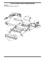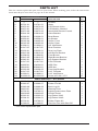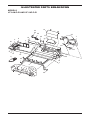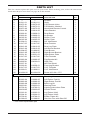
1
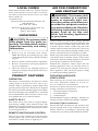
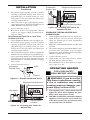
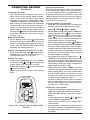
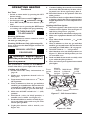
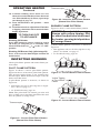
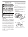
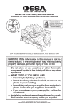
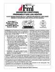
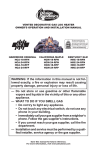
UNVENTED (VENT-FREE) GAS LOG HEATER
OWNER’S OPERATION AND INSTALLATION MANUAL
VF-24N-PJD, VF-24P-PJD
VF-18N-PJD, VF-18P-PJD
WARNING: If the information in this manual is not followed exactly, a fire or explosion may result causing
property damage, personal injury or loss of life.
— Do not store or use gasoline or other flammable
vapors and liquids in the vicinity of this or any other
appliance.
— WHAT TO DO IF YOU SMELL GAS
• Do not try to light any appliance.
• Do not touch any electrical switch; do not use any
phone in your building.
• Immediately call your gas supplier from a neighbor’s
phone. Follow the gas supplier’s instructions.
• If you cannot reach your gas supplier, call the fire
department.
— Installation and service must be performed by a qualified installer, service agency or the gas supplier.
INSTALLER: Leave this manual with the appliance.
CONSUMER: Retain this manual for future reference.
For more information, visit www.desatech.com
WARNING: Improper installation, adjustment, alteration, service or maintenance can cause injury or property damage. Refer to this manual for correct installation
and operational procedures. For assistance or additional information consult a qualified installer, service
agency or the gas supplier.
WARNING: This appliance is for installation only in a
solid-fuel burning masonry or UL127 factory-built fireplace or in a listed ventless firebox enclosure. It is design-certified for these installations in accordance with
ANSI Z21.11.2. Exception: Do not install this appliance
in a factory-built fireplace that includes instructions
stating it has not been tested or should not be used with
unvented gas logs.
WARNING: This is an unvented gas-fired heater. It uses
air (oxygen) from the room in which it is installed. Provisions for adequate combustion and ventilation air must
be provided. Refer to Air for Combustion and Ventilation
section on page 5 of this manual.
This appliance may be installed in an aftermarket,* permanently located, manufactured (mobile) home, where
not prohibited by local codes.
This appliance is only for use with the type of gas indicated on the rating plate. This appliance is not convertible for use with other gases.
* Aftermarket: Completion of sale, not for purpose of resale, from the manufacturer
TABLE OF CONTENTS
Safety Information ............................................... 3
Product Identification ........................................... 4
Local Codes ........................................................ 5
Unpacking ........................................................... 5
Product Features ................................................. 5
Air For Combustion and Ventilation ..................... 5
Installation ........................................................... 8
Operating Heater ............................................... 14
Inspecting Burners ........................................... 18
Cleaning and Maintenance ................................ 19
2
Troubleshooting ................................................. 20
Wiring Diagram .................................................. 23
Service Hints ..................................................... 24
Technical Service .............................................. 24
Replacement Parts ............................................ 24
Specifications .................................................... 25
Accessories ....................................................... 25
Illustrated Parts Breakdown and Parts List ....... 26
Warranty Information ...........................Back Cover
www.desatech.com
111826-04A
SAFETY INFORMATION
WARNING: This product contains and/or generates chemicals
known to the State of California
to cause cancer or birth defects
or other reproductive harm.
IMPORTANT: Read this owner’s
manual carefully and completely
before trying to assemble,
operate or service this heater.
Improper use of this heater can
cause serious injury or death
from burns, fire, explosion,
electrical shock and carbon
monoxide poisoning.
DANGER: Carbon monoxide
poisoning may lead to death!
Carbon Monoxide Poisoning: Early signs of carbon
monoxide poisoning resemble the flu, with headaches, dizziness or nausea. If you have these signs,
the heater may not be working properly. Get fresh
air at once! Have heater serviced. Some people
are more affected by carbon monoxide than others.
These include pregnant women, people with heart
or lung disease or anemia, those under the influence
of alcohol and those at high altitudes.
Natural and Propane/LP Gas: Natural and propane/LP gases are odorless. An odor-making
agent is added to these gases. The odor helps you
detect a gas leak. However, the odor added to the
gas can fade. Gas may be present even though no
odor exists.
Make certain you read and understand all warnings. Keep this manual for reference. It is your
guide to safe and proper operation of this heater.
WARNING: Any change to
this heater or its controls can
be dangerous.
WARNING: Do not use a
blower insert, heat exchanger
insert or other accessory not approved for use with this heater.
111826-04A
WARNING: Do not allow fans
to blow directly into the heater.
Avoid any drafts that alter burner
flame patterns. Ceiling fans can
create drafts that alter burner
flame patterns. Altered burner
patterns can cause sooting.
WARNING: Do not place
log scraps or lava rocks on
burner.
Due to high temperatures, the
appliance should be located out
of traffic and away from furniture
and draperies.
Do not place clothing or other
flammable material on or near
the appliance. Never place any
objects on the heater.
Heater base assembly becomes
very hot when running heater.
Keep children and adults away
from hot surface to avoid burns
or clothing ignition. Heater
will remain hot for a time after
shutdown. Allow surface to cool
before touching.
Carefully supervise young children when they are in the room
with heater.
You must operate this heater
with a fireplace screen in place.
Make sure fireplace screen is
closed before running heater.
Keep the appliance area clear
and free from combustible materials, gasoline and other flammable vapors and liquids.
www.desatech.com
3
SAFETY INFORMATION
Continued
1. This appliance is only for use with the type of
gas indicated on the rating plate. This appliance
is not convertible for use with other gases.
2. Do not place propane/LP supply tank(s) inside any structure. Locate propane/LP supply
tank(s) outdoors (propane/LP units only).
3. If you smell gas
• shut off gas supply
• do not try to light any appliance
• do not touch any electrical switch; do not
use any phone in your building
• immediately call your gas supplier from
a neighborʼs phone. Follow the gas
supplierʼs instructions
• if you cannot reach your gas supplier, call
the fire department
4. This heater shall not be installed in a bedroom
or bathroom.
5. Before installing in a solid fuel burning fireplace, the chimney flue and firebox must be
cleaned of soot, creosote, ashes and loose paint
by a qualified chimney cleaner. Creosote will
ignite if highly heated. Inspect chimney flue
for damage. If damaged, repair flue before
operating heater.
6. Do not burn solid-fuel in a masonry or UL127
factory-built fireplace in which a vent-free
room heater is installed.
7. If fireplace has glass doors, never operate this
heater with glass doors closed. If you operate
heater with doors closed, heat buildup inside
fireplace will cause glass to burst. Make sure
there are no obstructions across openings of
fireplace.
8. To prevent the creation of soot, follow the
instructions in Cleaning and Maintenance,
page 19.
9. Before using furniture polish, wax, carpet
cleaner or similar products, turn heater off. If
heated, the vapors from these products may
create a white powder residue within burner
box or on adjacent walls or furniture.
10. This heater needs fresh, outside air ventilation to
run properly. This heater has an oxygen depletion
sensing (ODS) pilot light safety system. The
ODS shuts down the heater if not enough fresh
air is available. See Air for Combustion and
Ventilation, page 5. If heater keeps shutting off,
see Troubleshooting, page 20.
11. Do not run heater
• where flammable liquids or vapors are
used or stored
• under dusty conditions
4
12. Do not use this heater to cook food or burn
paper or other objects.
13. Do not use heater if any part has been exposed
to or under water. Immediately call a qualified
service technician to inspect the room heater
and to replace any part of the control system and
any gas control which has been under water.
14. Do not operate heater if any log is broken. Do
not operate heater if a log is chipped (dimesized or larger).
15. Turn heater off and let cool before servicing
or repairing. Only a qualified service person
should install, service or repair heater.
16. This heater does not need to be connected to
any external electrical source.
17. To prevent performance problems, do not
use propane/LP fuel tank of less than 100 lb.
capacity (propane/LP units only).
18. Operating heater above elevations of 4,500
feet could cause pilot outage.
19. Provide adequate clearances around air
openings.
State of Massachusetts: The installation must be made by a licensed plumber
or gas fitter in the Commonwealth of
Massachusetts.
Sellers of unvented propane or natural
gas-fired supplemental room heaters shall
provide to each purchaser a copy of 527
CMR 30 upon sale of the unit.
Vent-free gas products are prohibited for
bedroom and bathroom installation in the
Commonwealth of Massachusetts.
PRODUCT
IDENTIFICATION
Log Set
Assembly
Control
Valve
Chassis
Assembly
Hand-Held
Remote Control
Figure 1 - Product Identification
www.desatech.com
111826-04A
LOCAL CODES
Install and use heater with care. Follow all local
codes. In the absence of local codes, use the latest edition of The National Fuel Gas Code ANSI
Z223.1/NFPA 54*.
*Available from:
American National Standards Institute, Inc.
1430 Broadway
New York, NY 10018
National Fire Protection Association, Inc.
Batterymarch Park
Quincy, MA 02269
UNPACKING
CAUTION: Do not remove the
data plates from the grate assembly. The data plates contain
important warranty and safety
information.
1. Remove log set assembly from carton.
Note: Do not pick up assembly by logs. This
could damage heater. Always handle assembly
by grate.
2. Remove control cover floor media components.
3. Remove all protective packaging applied to
log set for shipment.
3. Check all items for any shipping damage. If
damaged, promptly inform dealer where you
bought heater.
PRODUCT FEATURES
OPERATION
This heater is clean burning. It requires no outside
venting. There is no heat loss out a vent or up a
chimney. Heat is generated by realistic flames and
glowing ceramic logs/coals. This heater is designed
for vent-free operation with flue damper closed. It has
been tested and approved to ANSI Z21.11.2 standard
for unvented heaters. State and local codes in some
areas prohibit the use of vent-free heaters.
SAFETY PILOT
This heater has a pilot with an Oxygen Depletion Sensing (ODS) safety shutoff system. The
ODS/pilot is a required feature for vent-free room
heaters. The ODS/pilot shuts off the heater if there
is not enough fresh air.
REMOTE IGNITION AND CONTROL
AIR FOR COMBUSTION
AND VENTILATION
WARNING: This heater shall
not be installed in a confined
space or unusually tight construction unless provisions are
provided for adequate combustion and ventilation air. Read the
following instructions to insure
proper fresh air for this and
other fuel-burning appliances
in your home.
Todayʼs homes are built more energy efficient
than ever. New materials, increased insulation and
new construction methods help reduce heat loss
in homes. Home owners weather strip and caulk
around windows and doors to keep the cold air out
and the warm air in. During heating months, home
owners want their homes as airtight as possible.
While it is good to make your home energy efficient,
your home needs to breathe. Fresh air must enter
your home. All fuel-burning appliances need fresh
air for proper combustion and ventilation.
Exhaust fans, fireplaces, clothes dryers and fuel
burning appliances draw air from the house to
operate. You must provide adequate fresh air for
these appliances. This will insure proper venting
of vented fuel-burning appliances.
PROVIDING ADEQUATE
VENTILATION
The following are excerpts from National Fuel
Gas Code, ANSI Z223.1/NFPA 54, Section 5.3,
Air for Combustion and Ventilation.
All spaces in homes fall into one of the three following ventilation classifications:
1. Unusually Tight Construction
2. Unconfined Space
3. Confined Space
The information on pages 5 through 7 will help you
classify your space and provide adequate ventilation.
Unusually Tight Construction
The air that leaks around doors and windows may
provide enough fresh air for combustion and ventilation. However, in buildings of unusually tight
construction, you must provide additional fresh air.
This gas log set has a battery powered electronic
remote ignition and control. This system requires
no matches or other source to light log set.
111826-04A
www.desatech.com
5
AIR FOR COMBUSTION
AND VENTILATION
Continued
Unusually tight construction is defined as
construction where:
a. walls and ceilings exposed to the outside atmosphere have a continuous
water vapor retarder with a rating of one
perm (6 x 10-11 kg per pa-sec-m2) or less
with openings gasketed or sealed and
b. weather stripping has been added on
openable windows and doors and
c. caulking or sealants are applied to
areas such as joints around window
and door frames, between sole plates
and floors, between wall-ceiling joints,
between wall panels, at penetrations
for plumbing, electrical and gas lines
and at other openings.
If your home meets all of the three criteria
above, you must provide additional fresh air.
See Ventilation Air From Outdoors, page 7.
If your home does not meet all of the three
criteria above, proceed to Determining
Fresh-Air Flow For Heater Location.
Confined and Unconfined Space
The National Fuel Gas Code, ANSI Z223.1/NFPA
54 defines a confined space as a space whose
volume is less than 50 cubic feet per 1,000 Btu
per hour (4.8 m3 per kw) of the aggregate input
rating of all appliances installed in that space and
an unconfined space as a space whose volume is
not less than 50 cubic feet per 1,000 Btu per hour
(4.8 m3 per kw) of the aggregate input rating of
all appliances installed in that space. Rooms communicating directly with the space in which the
appliances are installed*, through openings not
furnished with doors, are considered a part of the
unconfined space.
* Adjoining rooms are communicating only if
there are doorless passageways or ventilation grills
between them.
DETERMINING FRESH-AIR FLOW
FOR HEATER LOCATION
Determining if You Have a Confined or
Unconfined Space
Use this work sheet to determine if you have a
confined or unconfined space.
Space: Includes the room in which you will install
heater plus any adjoining rooms with doorless passageways or ventilation grills between the rooms.
6
1.
Determine the volume of the space (length x
width x height).
Length x Width x Height =__________cu. ft.
(volume of space)
Example: Space size 20 ft. (length) x 16 ft.
(width) x 8 ft. (ceiling height) = 2,560 cu. ft.
(volume of space)
If additional ventilation to adjoining room is
supplied with grills or openings, add the volume
of these rooms to the total volume of the space.
2. Multiply the space volume by 20 to determine
the maximum Btu/Hr the space can support.
__________ (volume of space) x 20 = (Maximum Btu/Hr the space can support)
Example: 2,560 cu. ft. (volume of space) x 20 =
51,200 (maximum Btu/Hr the space can support)
3. Add the Btu/Hr of all fuel burning appliances in
the space.
Vent-free fireplace
__________ Btu/Hr
Gas water heater*
__________ Btu/Hr
Gas furnace
__________ Btu/Hr
Vented gas heater
__________ Btu/Hr
Gas fireplace logs
__________ Btu/Hr
Other gas appliances* + __________ Btu/Hr
Total
= __________ Btu/Hr
* Do not include direct-vent gas appliances. Direct-vent draws combustion air from the outdoors
and vents to the outdoors.
Example:
40,000
Gas water heater
__________
Btu/Hr
33,000
Vent-free fireplace
+ __________
Btu/Hr
73,000
Total
= __________
Btu/Hr
4. Compare the maximum Btu/Hr the space can
support with the actual amount of Btu/Hr used.
_________Btu/Hr (maximum the space can support)
_________ Btu/Hr (actual amount of Btu/Hr used)
Example: 51,200 Btu/Hr (maximum the space
can support)
73,000 Btu/Hr (actual amount of
Btu/Hr used)
The space in the example is a confined space because
the actual Btu/Hr used is more than the maximum
Btu/Hr the space can support. You must provide additional fresh air. Your options are as follows:
A. Rework worksheet, adding the space of an adjoining room. If the extra space provides an unconfined
space, remove door to adjoining room or add
ventilation grills between rooms. See Ventilation
Air From Inside Building, page 7.
B. Vent room directly to the outdoors. See Ventilation Air From Outdoors, page 7.
C. Install a lower Btu/Hr fireplace, if lower Btu/Hr
size makes room unconfined.
www.desatech.com
111826-04A
AIR FOR COMBUSTION
AND VENTILATION
Continued
If the actual Btu/Hr used is less than the maximum
Btu/Hr the space can support, the space is an unconfined space. You will need no additional fresh air
ventilation.
WARNING: If the area in
which the heater may be operated is smaller than that defined
as an unconfined space or if the
building is of unusually tight
construction, provide adequate
combustion and ventilation air
by one of the methods described
in the National Fuel Gas Code,
ANSI Z223.1/NFPA 54 Section 5.3
or applicable local codes.
VENTILATION AIR
Ventilation Air From Inside Building
This fresh air would come from an adjoining unconfined space. When ventilating to an adjoining
unconfined space, you must provide two permanent
openings: one within 12" of the ceiling and one
within 12" of the floor on the wall connecting the
two spaces (see options 1 and 2, Figure 2). You
can also remove door into adjoining room (see
option 3, Figure 2). Follow the National Fuel Gas
Code, ANSI Z223.1/NFPA 54, Section 5.3, Air for
Combustion and Ventilation for required size of
ventilation grills or ducts.
Ventilation Air From Outdoors
Provide extra fresh air by using ventilation grills or
ducts. You must provide two permanent openings:
one within 12" of the ceiling and one within 12"
of the floor. Connect these items directly to the
outdoors or spaces open to the outdoors. These
spaces include attics and crawl spaces. Follow the
National Fuel Gas Code, ANSI Z223.1/NFPA 54,
Section 5.3, Air for Combustion and Ventilation for
required size of ventilation grills or ducts.
IMPORTANT: Do not provide openings for inlet
or outlet air into attic if attic has a thermostatcontrolled power vent. Heated air entering the attic
will activate the power vent.
Outlet
Air
Outlet
Air
Ventilated
Attic
To Attic
To
Crawl
Space
Inlet
Air
Inlet Air
Ventilated
Crawl Space
Figure 3 - Ventilation Air from Outdoors
12"
Ventilation
Grills
Into Adjoining
Room,
Option 1
Ventilation Grills
Into Adjoining Room,
Option 2
Or
Remove
Door into
Adjoining
Room,
Option
3
12"
Figure 2 - Ventilation Air from Inside
Building
111826-04A
www.desatech.com
7
INSTALLATION
NOTICE: This heater is intended
for use as supplemental heat.
Use this heater along with your
primary heating system. Do not
install this heater as your primary heat source. If you have a
central heating system, you may
run system’s circulating blower
while using heater. This will help
circulate the heat throughout the
house. In the event of a power
outage, you can use this heater
as your primary heat source.
WARNING: A qualified service person must install heater.
Follow all local codes.
WARNING: Before installing in
a solid fuel burning fireplace, the
chimney flue and firebox must be
cleaned of soot, creosote, ashes
and loose paint by a qualified chimney cleaner. Creosote will ignite
if highly heated. A dirty chimney
flue may create and distribute soot
within the house. Inspect chimney
and firebox flue for damage. If
damaged, repair flue and firebox
before operating heater.
WARNING: Seal any fresh
air vents or ash clean-out doors
located on floor or wall of fireplace. If not, drafting may cause
pilot outage or sooting. Use a
heat-resistant sealant. Do not
seal chimney flue damper.
8
WARNING: Never install the
heater
• in a bedroom or bathroom
• in a recreational vehicle
• where curtains, furniture, clothing or other flammable objects
are less than 42 inches from the
front, top or sides of the heater
• in high traffic areas
• in windy or drafty areas
CAUTION: This heater creates warm air currents. These
currents move heat to wall surfaces next to heater. Installing
heater next to vinyl or cloth wall
coverings or operating heater
where impurities (such as, but
not limited to, tobacco smoke,
aromatic candles, cleaning fluids, oil or kerosene lamps, etc.) in
the air exist, may discolor walls
or cause odors.
IMPORTANT: Vent-free heaters add moisture to
the air. Although this is beneficial, installing heater
in rooms without enough ventilation air may cause
mildew to form from too much moisture. See Air
for Combustion and Ventilation, page 5.
CHECK GAS TYPE
Use the correct gas type (natural or propane/LP)
for your unit. If your gas supply is not correct, do
not install heater. Call dealer where you bought
heater for proper type heater.
WARNING: This appliance
is equipped for (natural or propane/LP) gas. Field conversion
is not permitted.
www.desatech.com
111826-04A
INSTALLATION
Continued
Example
INSTALLATION AND CLEARANCES
FOR VENT-FREE OPERATION
WARNING: Maintain the
minimum clearances. If you can,
provide greater clearances from
floor, ceiling and adjoining wall.
MINIMUM FIREPLACE
CLEARANCE TO
COMBUSTIBLE MATERIALS
Log Size
18" or 24"
Side Wall
16"
Ceiling
42"
Floor
5"
LOG SIZING REQUIREMENTS
Minimum Firebox Size
Log
Front
Rear*
Size Height Depth Width Width
18"
17"
14"
24"
20"
24"
17"
14"
28"
22"
*Measured at 14" depth
Carefully follow the instructions below. This will
ensure safe installation into a masonry, UL127listed manufactured fireplace or listed vent-free
firebox enclosure.
Minimum Clearances For Side
Combustible Material, Side Wall and
Ceiling
A. Clearances from the side of the fireplace
cabinet to any combustible material and wall
should follow diagram in Figure 4.
Example: The face of a mantel, bookshelf,
etc. is made of combustible material and
protrudes 3 1/2" from the wall. This combustible material must be 4" from the side of the
fireplace cabinet (see Figure 4).
Note: When installing your gas logs into
a manufactured firebox, follow firebox
manufacturerʼs instructions for minimum
clearances to combustible materials.
B. Clearances from the top of the fireplace opening
to the ceiling should not be less than 42 inches.
111826-04A
*
*Minimum 16 inches from Side Wall
Figure 4 - Minimum Clearance for
Combustible to Wall
Minimum Noncombustible Material
Clearances
If Not Using Mantel
Note: If using a mantel, proceed to If Using
Mantel. If not using a mantel, follow the information below.
You must have noncombustible material(s) above
fireplace opening. Noncombustible materials
(such as slate, marble, tile, etc.) must be at least
1/2 inch thick. With sheet metal, you must have
noncombustible material behind it. Noncombustible material must extend at least 8" up (for all
models). If noncombustible material is less than
12", you must install the fireplace hood accessory
- 24" models only). See Figure 5, page 10, for
minimum clearances.
If Using Mantel
You must have noncombustible material(s) above
the fireplace opening. Noncombustible materials
(such as slate, marble, tile, etc.) must be at least
1/2 inch thick. With sheet metal, you must have
noncombustible material behind it. Noncombustible material must extend at least 8 inches up (for
all models). If noncombustible material is less than
12", you must install the fireplace hood accessory.
Even if noncombustible material is more than 12",
you may need the hood accessory to deflect heat
away from your mantel shelf. See Figures 5, 6 and
7, page 10, for minimum clearances.
www.desatech.com
9
INSTALLATION
Continued
Noncombustible
Material
Distance (A)
12" or more
Between 8"
and 12"
Less than 8"
Requirements for
Safe Installation
Noncombustible material OK.
24" Model:Install fire place hood accessory
(GA6060, see Accessories, page 25).
18" Model: Noncombustible material OK
Noncombustible material must be
extended to at least 8". See Between 8"
and 12", above. If you cannot extend material,
you must operate heater with flue damper
open.
Figure 5 - Heat Resistant Material (Slate, Marble, Tile, etc.) Above Fireplace
Mantel Shelf
10"
Underside of
Mantel Shelf
8"
6"
2 1/2"
All minimum
distances are
in inches
Minimum NonCombustible
Material
(A)
12"
18"
20"
22"
24"
Top of Fireplace
Opening
Minimum NonCombustible
Material Height
Distances to
Underside of
Mantel
Figure 6 - Minimum Mantel Clearances Without Using Hood
Mantel Shelf
12"
Underside
of Mantel
Shelf
10"
8"
6"
2 1/2"
Minimum
Noncombustible
Material
All minimum
distances are
in inches
8"
12"
Min.
Hood
(GA6050,
GA6052 or
GA6053)
15"
18"
Distances to
Underside of
Mantel
20"
Top of
Fireplace
Opening
Figure 7 - Minimum Mantel Clearances When Using Hood
10
www.desatech.com
111826-04A
INSTALLATION
Continued
MANTEL CLEARANCES
In addition to meeting noncombustible material
clearances, you must also meet required clearances
between fireplace openings and mantel shelf on
each side of the fireplace. If you do not meet the
clearances listed below, you will need a hood.
Determining Minimum Mantel Clearance
If you meet minimum clearance between mantel
shelf and top of fireplace opening, a hood is not
required (see Figure 6, page 10).
Determining Minimum Mantel Clearance
When using a Hood
If minimum clearances in Figure 6, page 11 are not
met, you must have a hood. When using a hood
there are still certain minimum mantel clearances
required. Follow minimum clearances shown in
Figure 7, page 10 when using hood.
NOTICE: Surface temperatures
of adjacent walls and mantels become hot during operation. Walls
and mantels above the firebox
may become hot to the touch.
If installed properly, these temperatures meet the requirement
of the national product standard.
Follow all minimum clearances
shown in this manual.
NOTICE: If your installation does
not meet the minimum clearances shown, you must do one
of the following:
• operate the logs only with the
flue damper open
• raise the mantel to an acceptable height
• remove the mantel
FLOOR CLEARANCES
A. If installing appliance on the floor level, you
must maintain the minimum distance of 14"
to combustibles (see Figure 8).
B. If combustible materials are less than 14" to
the fireplace, you must install appliance at
least 5" above the combustible flooring (see
Figure 9).
111826-04A
Combustible
Material
14"
Min.
Noncombustible Material
Figure 8 - Minimum Fireplace Clearances
If Installed at Floor Level
Hearth
Combustible
Material
5"
Min.
Figure 9 - Minimum Fireplace Clearances
Above Combustible Flooring
INSTALLING HEATER ASSEMBLY
CAUTION: Do not remove the
data plates attached to the heater
base assembly. The data plates
contain important warranty and
safety information.
WARNING: If installing in a
sunken fireplace, special care
is needed. You must raise the
fireplace floor to allow access to
heater control panel. This will insure adequate air flow and guard
against sooting and controls being damaged. Raise fireplace floor
with noncombustible material.
Make sure material is secure.
CAUTION: Do not pick up
heater assembly by the logs. This
could damage heater. Only handle base assembly by grates.
IMPORTANT: Make sure the heater burner is level.
If heater is not level, heater will not work properly.
www.desatech.com
11
INSTALLATION
Continued
Installation Items Needed
• control cover kit (provided with heater)
• approved flexible gas hose (not provided) (if
allowed by local codes)
• sealant (resistant to propane/LP gas, not
provided)
1. Apply pipe joint sealant lightly to male threads
of gas fitting (not provided). Connect approved
flexible gas hose to inlet side of gas control (see
Figure 10). IMPORTANT: Hold gas fitting with
wrench when connecting flexible gas hose.
2. Position heater assembly in fireplace.
3. Connect to gas supply. See Connecting to
Gas Supply.
Flexible Gas Hose
(if allowed by local codes)
Fitting
Figure 10 - Attaching Flexible Gas Hose
to Regulator
CONNECTING TO GAS SUPPLY
WARNING: This appliance
requires a 1/2" NPT (National
Pipe Thread) inlet connection to
the pressure regulator.
WARNING: A qualified service
person must connect heater to gas
supply. Follow all local codes.
CAUTION: Never connect
propane/LP fireplace directly
to the propane/LP supply. This
heater requires an external regulator (not supplied). Install the
external regulator between the
heater and propane/LP supply.
WARNING: Never connect
natural gas fireplace to private
(non-utility) gas wells. This gas
is commonly known as wellhead
gas.
12
Installation Items Needed
Before installing heater, make sure you have the
items listed below.
• external regulator (for propane/LP units only,
supplied by installer)
• piping (check local codes)
• sealant (resistant to propane/LP gas)
• equipment shutoff valve *
• test gauge connection *
• sediment trap
• tee joint
• pipe wrench
• approved flexible gas line with gas connector
(if allowed by local codes) (not provided)
* A CSA design-certified equipment shutoff valve
with 1/8" NPT tap is an acceptable alternative to
test gauge connection. Purchase the optional CSA
design-certified equipment shutoff valve from your
dealer. See Accessories, page 25.
For propane/LP units, the installer must supply
an external regulator. The external regulator will
reduce incoming gas pressure. You must reduce
incoming gas pressure to between 11 and 14 inches
of water. If you do not reduce incoming gas pressure, heater regulator damage could occur. Install
external regulator with the vent pointing down
as shown in Figure 11. Pointing the vent down
protects it from freezing rain or sleet.
CAUTION: Use only new, black
iron or steel pipe. Internally-tinned
copper tubing may be used in
certain areas. Check your local
codes. Use pipe of 1/2" diameter or
greater to allow proper gas volume
to heater. If pipe is too small, undue
loss of volume will occur.
Propane/LP
Supply Tank
External
Regulator
Vent
Pointing
Down
Figure 11 - External Regulator With Vent
Pointing Down
www.desatech.com
111826-04A
INSTALLATION
Continued
Installation must include an equipment shutoff
valve, union and plugged 1/8" NPT tap. Locate NPT
tap within reach for test gauge hook up. NPT tap
must be upstream from heater (see Figure 12).
IMPORTANT: Install equipment shutoff valve
in an accessible location. The equipment shutoff
valve is for turning on or shutting off the gas to
the appliance.
Check your building codes for any special requirements for locating equipment shutoff valve
to fireplaces.
Apply pipe joint sealant lightly to male NPT
threads. This will prevent excess sealant from
going into pipe. Excess sealant in pipe could result
in clogged heater valves.
WARNING: Use pipe joint
sealant that is resistant to liquid
petroleum (LP) gas.
CSA Design-Certified
Equipment Shutoff Valve
With 1/8" NPT Tap*
To Gas
Control
Approved
Flexible Gas
Hose (if allowed
by local codes)
3" Minimum
Natural Gas
From Gas Meter
(5" W.C.** to 10.5"
W.C. Pressure)
Propane/LP Gas
From External
Regulator
(11" W.C.** to
14" W.C.
Pressure)
Cap Pipe Tee
Nipple Joint
Sediment Trap
Figure 12 - Gas Connection
* Purchase the optional CSA design-certified
equipment shutoff valve from your dealer. See
Accessories, page 25.
** Minimum inlet pressure for purpose of input
adjustment.
111826-04A
We recommend that you install a sediment trap in
supply line as shown in Figure 12. Locate sediment
trap where it is within reach for cleaning. Install
in piping system between fuel supply and heater.
Locate sediment trap where trapped matter is not
likely to freeze. A sediment trap traps moisture and
contaminants. This keeps them from going into
heater controls. If sediment trap is not installed or
is installed wrong, heater may not run properly.
CAUTION: Avoid damage to
gas control. Hold gas control
with wrench when connecting it
to gas piping and/or fittings.
CHECKING GAS CONNECTIONS
WARNING: Test all gas piping
and connections, internal and
external to unit, for leaks after
installing or servicing. Correct
all leaks at once.
WARNING: Never use an
open flame to check for a leak.
Apply a noncorrosive leak detection fluid to all joints. Bubbles
forming show a leak. Correct all
leaks at once.
CAUTION: Make sure external regulator has been installed
between propane/LP supply
and heater. See guidelines under Connecting to Gas Supply,
page 12.
PRESSURE TESTING GAS SUPPLY
PIPING SYSTEM
Test Pressures In Excess Of 1/2 PSIG
(3.5 kPa)
1. Disconnect appliance with its appliance main
gas valve (control valve) and equipment
shutoff valve from gas supply piping system.
Pressures in excess of 1/2 psig will damage
heater regulator.
2. Cap off open end of gas pipe where equipment
shutoff valve was connected.
www.desatech.com
13
INSTALLATION
Propane/LP
Supply Tank
Continued
3. Pressurize supply piping system by either
opening propane/LP supply tank valve for
propane/LP gas or opening main gas valve
located on or near gas meter for natural gas
or using compressed air.
4. Check all joints of gas supply piping system.
Apply noncorrosive leak detection fluid to all
joints. Bubbles forming show a leak.
5. Correct all leaks at once.
6. Reconnect heater and equipment shutoff
valve to gas supply. Check reconnected fittings for leaks.
Test Pressures Equal To or Less Than
1/2 PSIG (3.5 kPa)
1. Close equipment shutoff valve (see Figure 13).
2. Pressurize supply piping system by either
opening propane/LP supply tank valve for
propane/LP gas or opening main gas valve
located on or near gas meter for natural gas
or using compressed air.
3. Check all joints from gas meter to equipment
shutoff valve for natural gas or propane/LP supply to equipment shutoff valve for propane/LP
(see Figure 14 or 15). Apply noncorrosive leak
detection fluid to all joints. Bubbles forming
show a leak.
4. Correct all leaks at once.
Equipment
Shutoff Valve
Open
Equipment Shutoff Valve
Control Valve Location
Figure 15 - Checking Gas Joints for
Propane/LP Gas
PRESSURE TESTING HEATER GAS
CONNECTIONS
1. Open equipment shutoff valve (see Figure 13).
2. Open main gas valve located on or near gas
meter for natural gas or open propane/LP
supply tank valve.
3. Make sure control knob of heater is in the OFF
position.
4. Check all joints from equipment shutoff valve
to control valve (see Figure 14 or 15). Apply
noncorrosive leak detection fluid to all joints.
Bubbles forming show a leak.
5. Correct all leaks at once.
6. Light heater (see Operating Heater). Check
all other internal joints for leaks.
7. Turn off heater (see To Turn Off Gas to Appliance, page 17 or 18).
OPERATING HEATER
FOR YOUR SAFETY
READ BEFORE LIGHTING
Closed
Figure 13 - Equipment Shutoff Valve
Equipment Shutoff Valve
Gas Meter
Control Valve
Location
WARNING: If you do not follow these instructions exactly,
a fire or explosion may result
causing property damage, personal injury or loss of life.
A. This appliance has a pilot which must be
lighted by hand. When lighting the pilot,
follow these instructions exactly.
B. BEFORE LIGHTING smell all around the
appliance area for gas. Be sure to smell next
to the floor because some gas is heavier than
air and will settle on the floor.
Figure 14 - Checking Gas Joints for
Natural Gas
14
www.desatech.com
111826-04A
OPERATING HEATER
Continued
WHAT TO DO IF YOU SMELL GAS
• Do not try to light any appliance.
• Do not touch any electric switch; do not
use any phone in your building.
• Immediately call your gas supplier
from a neighborʼs phone. Follow the
gas supplierʼs instructions.
• If you cannot reach your gas supplier,
call the fire department.
C. Use only your hand to push in or turn the
gas control knob. Never use tools. If the
knob will not push in or turn by hand, donʼt
try to repair it, call a qualified service technician or gas supplier. Force or attempted
repair may result in a fire or explosion.
D. Do not use this appliance if any part has
been under water. Immediately call a
qualified service technician to inspect the
appliance and to replace any part of the
control system and any gas control which
has been under water.
REMOTE LIGHTING
INSTRUCTIONS
WARNING:
• If fireplace has glass doors,
never operate this heater with
glass doors closed. If you operate heater with doors closed,
heat buildup inside fireplace
will cause glass to burst. Make
sure there are no obstructions
across openings of fireplace.
• You must operate this heater
with a fireplace screen in place.
Make sure fireplace screen is
closed before running heater.
NOTICE: During initial operation
of new heater, burning logs will
give off a paper-burning smell.
Orange flame will also be present. Open damper or window to
vent smell. This will only last a
few hours.
111826-04A
CAUTION: A mild gas flash
within 10 seconds is normal
during shutdown of this heater.
Remain clear of the hearth area
for the entire shutdown process
to avoid possible injury.
1. STOP! Read the safety information beginning on page 14.
2. Make sure equipment shutoff valve is fully
open.
to the
3. Turn motor knob clockwise
OFF position.
4. Wait five (5) minutes to clear out any gas.
Then smell for gas, including near the floor.
If you smell gas, STOP! Follow “B” in the
safety information, page 14. If you donʼt
smell gas, go to the next step.
5. Make sure ON/OFF switch is in "–" (ON)
position.
WARNING: Burner will come
on automatically within one minute after pilot burner is lighted.
6. Press the buttons
and
at the same
time. A short acoustic signal confirms the
start sequence has begun.
Further short acoustic signals (0.2 sec., 1 Hz)
indicate the ignition process until it is completed and main gas flows. If pilot is already
lit, motor will turn on (max. flame height)
while buttons are pressed down. If pilot does
not light, see Troubleshooting, page 20.
to turn on main burner and in7. Press
crease flame height. Press
to decrease
flame height and shut off main burner.
8. Short tapping of either button allows incremental change in flame height.
9. Press OFF button to switch off main gas
and pilot gas.
FUNCTIONS OF
REMOTE CONTROL
Battery
• After the charged battery has been correctly
installed, the remote hand set is ready for
operations.
• Remove the battery if the remote handset
will not be used more than one year.
www.desatech.com
15
OPERATING HEATER
Continued
Changing The Code
• The control is radio frequency operated. A
code (chosen from among 4,000 available
codes) is preset for all valves, but can be
changed if required (15 additional codes
available). Change DIP switch position. (The
DIP switch is located inside the hand held
control at the top of the battery compartment.) Then press the receiver's reset button
until you hear a second (longer) signal. When
button on the remote handset
pressing the
in the following 20 sec., the receiver learns
the new code.
Shut-off Procedure
• To save battery power; press
to turn main
gas to pilot gas. Press OFF button to shut off
the device including pilot flame. The device
can be shut off with ON/OFF switch, thus
disabling the remote hand set.
Setting The Display ( °C/24h and °F /12h)
• Press and hold OFF and
until display
changes from °F (and 12 hour clock) to °C
(and 24 hour clock) or vice versa.
Setting The Time
• After connecting the battery or by simultaand
the display will
neously pressing
start to flash. You are in the set mode.
to set the hour and
• From SET mode press
to set the minute.
• Wait or press OFF to return to the manual
mode.
SET
OFF
STAND
BY
Figure 16 - Control Panel for Hand-Held
Remote
16
Battery Replacement
Remote handset battery needs to be changed
when LED is dim. Battery life expectancy is 2
to 3 years. Replacement is recommended at the
beginning of heating season. Battery needs to be
changed when acoustic error message appears
during ignition (see Identifying Error Signals
from Receiver on page 23).
Changing Mode of Operation
• Press the SET button quickly to change the
mode of operation in the following order:
MAN,
TEMP, TEMP, TIMER.
• Manual flame height adjustment (MAN appears on display): Press
to turn on the fire
(main burner) or to increase flame height.
Press
to decrease flame or to go down
to pilot only. The receiver acknowledges the
transmission with an acoustic signal.
• The day time temperature mode ( TEMP appears on display): The sensor in the transmitter
measures room temperature. The controller
compares the room temperature with set temperature and sends a signal to the receiver to
turn the gas valve motor up or down, to adjust
the flame height accordingly.
• The nighttime setback temperature (
TEMP appears on display): The sensor in the
transmitter measures the temperature and
adjusts it according to the nighttime setback
temperature. There is a bigger temperature
differential during this cycle.
• Timer: The timer mode ( TIMER ) operates
much like the temperature mode above. The
timer setting allows you to set specific times
for on and off. (There are 2 burner on and
2 burner off cycles every 24 hours.) If the
reading for the nighttime temp. is "– – –",
the motor will turn off the valve to standby
pilot position and wait for the next burner
on cycle. This display shows the setting temperature every 30 seconds.
Setting the Temperature
• Select the desired mode of operation (day or
night) by pressing the SET button briefly.
• Hold the SET button until the display
flashes.
or
(40°F
• Set the temperature with the
is the minimum temperature).
• Wait or press OFF to go to temperature
control mode.
• If temperature control in moon times should
be off (lower battery consumption), decrease
the night temperature until "– – –" appears
on display.
www.desatech.com
111826-04A
OPERATING HEATER
Continued
Set Timer
• Switch to timer mode by pressing the SET
button briefly.
• Press the SET button until P1 flashes.
and minutes with
.
• Set the hours with
• Press SET briefly for the next burner cycle
time.
• If all 4 times are set, pressing the OFF button
or waiting will complete the programming.
TO TURN GAS OFF
TO APPLIANCE
Shutting Off Heater
Press OFF button on remote control to switch
off main gas and pilot gas.
Shutting Off Burner Only (pilot stays lit)
Press to decrease the flame height and shut off
main burner.
MANUAL LIGHTING
PROCEDURE
WARNING: Manual lighting
must be performed by a qualified
service person.
The system has a "MANUAL OVERRIDE"
feature that allows you to light with a match.
Lighting with a Match
1. STOP! Read the safety information on
page 14.
2. Make sure equipment shutoff valve is
fully open.
to
3. Turn motor-knob clockwise to
OFF position.
4. Wait (5) minutes to clear any gas and then
smell for gas around heater and near floor. If
you smell gas, STOP! follow "B" on page 14.
If you do not smell gas, go to the next step.
5. Make sure ON/OFF switch is in "–" (ON)
position.
6. MAN-knob (valve) in MAN position, a
metallic core is visible. (see Figure 17).
7. Push and hold down metal core fully by using a non-sharp object such as a pen. This
lets the pilot gas flow.
8. Light pilot burner with a match, (see
Figure 18).
111826-04A
9. Continue holding down metal core for about
10 seconds. Pilot should stay lit after releasing metal core. If not, repeat step 1 thru 4.
10. Turn MAN-knob to ON position. This lets
main gas flow.
11. Turn Motor-knob to adjust flame. Knob has
a slipping clutch that allows manual flame
height adjustment as well as adjustment to
pilot gas.
Lighting with Piezo Ignitor
1. Disconnect ignitor cable from receiver and
connect to Piezo Ignitor Tab (see Figure 17
and Wiring Diagram on page 24).
2. STOP! Read safety information on page 14,
3. Make sure equipment shutoff valve is fully
open.
to the
4. Turn Motor-knob clockwise
OFF position.
5. Wait (5) minutes to clear any gas and then
smell for gas around heater and near floor. If
you smell gas, STOP! follow "B" on page 14.
6. ON/OFF switch in "—" ON position.
7. MAN-knob on valve is in MAN position (see
Figure 17), When in MAN position you can
see a metallic core.
8. Push and hold down metal core fully with
a pen while the pilot gas flows.
9. Press and release piezo ignitor button until
pilot lights.
Metalic
Core for MAN-Knob
Manual in Manual
Ignition Position
Piezo
Ignitor
Tab
MotorKnob
in ON
Position
Piezo Ignitor
Microswitch
ON/OFF Switch
Figure 17 - PJD Control Valve
www.desatech.com
Figure 18 - Pilot
17
OPERATING HEATER
Continued
10. Continue holding down metal core for
about 10 seconds and then release the metal
core. Pilot should stay lit. If not, repeat steps
one through 4, page 17.
11. Turn MAN-Knob to ON position - main
gas flows.
12. Turn Motor-knob to adjust flame. Knob has
a slipping clutch that allows manual flame
height adjustment.
TO TURN GAS OFF
TO APPLIANCE
Shutting Off Heater
Press OFF button on remote control to switch
off main gas and pilot gas or manually turn
Motor-Knob clockwise
to the "O" OFF
position.
Shutting Off Burner Only (pilot stays lit)
Press to decrease the flame height and shut off
main burner.
Thermocouple
Figure 20 - Incorrect Pilot Flame Pattern
(Natural Gas Pilot Shown)
BURNER FLAME PATTERN
Figure 21 shows correct burner flame pattern.
NOTICE: Do not mistake orange
flames with yellow tipping. Dirt
or other fine particles are burned
by heater, causing brief patches
of orange flame.
If burner flame pattern is incorrect, as shown in
Figure 22
• turn appliance off (see To Turn Off Gas to Appliance in column 1 or page 17
• see Troubleshooting, page 20
INSPECTING BURNERS
Check pilot flame pattern and burner flame patterns often.
PILOT FLAME PATTERN
Figure 19 shows a correct pilot flame pattern.
Figure 20 shows an incorrect pilot flame pattern.
The incorrect pilot flame is not touching the
thermocouple. When the thermocouple cools, the
heater will shut down.
If pilot flame pattern is incorrect, as shown in
Figure 20
• turn heater off (see To Turn Off Gas to Appliance, above or page 17)
• see Troubleshooting, page 20
Note: The pilot flame on natural gas units will
have a slight curve, but flame should be blue and
have no yellow or orange color.
Figure 21 - Correct Burner Flame Pattern
Yellow Tipping
at Top of Blue
Flame
Figure 22 - Correct Burner Flame Pattern
Thermocouple
Figure 19 - Correct Pilot Flame Pattern
(Natural Gas Pilot Shown)
18
www.desatech.com
111826-04A
CLEANING AND
MAINTENANCE
WARNING: Turn off heater
and let cool before cleaning.
CAUTION: You must keep control areas, burner and circulating
air passageways of heater clean.
Inspect these areas of heater
before each use. Have heater
inspected yearly by a qualified
service person. Heater may need
more frequent cleaning due to
excessive lint from carpeting,
bedding material, pet hair, etc.
1. Remove the two screws that hold the front log
bracket onto the assembly (see Figure 23). The
log is attached to this bracket. Gently lift up
on the log and bracket. Set aside.
2. Inspect burner and primary air inlet holes
on injector holder for dust and dirt (see
Figure 24).
3. Blow air through the ports/slots and holes in
the burner.
4. Check the injector holder located at the end
of the burner tube again. Remove any large
particles of dust, dirt, lint or pet hair with a
soft cloth or vacuum cleaner nozzle.
5. Blow air into the primary air holes on the
injector holder.
6. In case any large clumps of dust have now been
pushed into the burner repeat steps 3 and 4.
WARNING: Failure to keep
the primary air opening(s) of
the burner(s) clean may result in
sooting and property damage.
Front
Log
BURNER INJECTOR HOLDER AIR
INLET HOLE
The primary air inlet holes allow the proper amount
of air to mix with the gas. This provides a clean
burning flame. Keep these holes clear of dust, dirt,
lint and pet hair. Clean these air inlet holes prior to
each heating season. Blocked air holes will create
soot. We recommend that you clean the unit every
three months during operation and have heater
inspected yearly by a qualified service person.
We also recommend that you keep the burner tube
clean and free of dust and dirt. We recommend
using compressed air no greater than 30 PSI. Your
local computer store, hardware store or home
center may carry compressed air in a can. You can
use a vacuum cleaner in the blow position. If using
compressed air in a can, please follow the directions on the can. If you don't follow directions on
the can, you could damage the pilot assembly.
Before cleaning, shut off the unit, including the
pilot. Allow the unit to cool for at least thirty
minutes. You will need to remove the front log to
access the front burner.
111826-04A
Figure 23 - Removing Front Log to Clean
Front Burner
Injector
Holder
Burner Tube
Primary Air
Inlet Opening
Figure 24 - Injector Holder on Front
Burner Tube
Injector
www.desatech.com
19
TROUBLESHOOTING
WARNING: Turn off heater and let cool before servicing. Only a
qualified service person should service and repair heater.
CAUTION: Never use a wire, needle or similar object to clean
ODS/pilot. This can damage ODS/pilot unit.
Note: All troubleshooting items are listed in order of operation.
OBSERVED PROBLEM
POSSIBLE CAUSE
REMEDY
When
and
are pressed
at the same time, there is no spark
at ODS/pilot
1. Ignitor electrode not connected to ignitor cable
2. Ignitor cable pinched or wet
1. Reconnect ignitor cable
3. Broken ignitor cable
4. Bad piezo ignitor
5. Ignitor electrode positioned
wrong or broken
6. Bad module
When
and
are pressed,
there is spark at ODS/pilot but
no ignition
1. Gas supply turned off or equipment shutoff valve closed
2. Control knob not in PILOT
position
3. Control knob not pressed in
while in PILOT position
4. Air in gas lines when installed
5. Depleted gas supply (propane/LP only)
6. ODS/pilot is clogged
7. Gas regulator setting is not
correct
8. Bad module
Burner does not light after pilot
is lit
1. Inlet gas pressure is too low
2. Burner orifice(s) clogged
3. Burner orifice(s) diameter is
too small
4. Wire disconnected from gas
control
5. Bad module
Delayed ignition burner
1. Manifold pressure is too
low
2. Burner orifice(s) clogged
20
www.desatech.com
2. Free ignitor cable if pinched
by any metal or tubing. Keep
ignitor cable dry
3. Replace ignitor cable
4. Replace piezo ignitor
5. Replace pilot assembly
6. Replace module
1. Turn on gas supply or open
equipment shutoff valve
2. Turn control knob to PILOT
position
3. Press in control knob while in
PILOT position
4. Continue holding down control knob. Repeat igniting operation until air is removed
5. Contact local propane/LP gas
company
6. Clean ODS/pilot (see Cleaning
and Maintenance, page 19) or
replace ODS/pilot assembly
7. Replace gas regulator
8. Replace module
1. Contact local natural or propane/LP gas company
2. Clean burner (see Cleaning
and Maintenance, page 19) or
replace burner orifice(s)
3. Replace burner orifice(s)
4. Reconnect leads (see Wiring
Diagram, page 24)
5. Replace module
1. Contact local natural or propane/LP gas company
2. Clean burner (see Cleaning
and Maintenance, page 19) or
replace burner orifice
111826-04A
TROUBLESHOOTING
OBSERVED PROBLEM
Continued
POSSIBLE CAUSE
Burner backfiring during combustion
1. Burner orifice is clogged or
damaged
2. Damaged burner
3. Gas regulator defective
1. Not enough air
REMEDY
1. Clean burner (see Cleaning
and Maintenance, page 19) or
replace burner orifice
2. Replace damaged burner
3. Replace gas regulator
2. Gas regulator defective
1. Check burner for dirt and
debris. If found, clean burner
(see Cleaning and Maintenance, page 19)
2. Replace gas control
Slight smoke or odor during
initial operation (first hour)
1. Residues from manufacturing
processes and logs curing
1. Problem will stop after a few
hours of operation
Heater produces a whistling noise
when burner is lit
1. Turning control knob to HI
position when burner is cold
2. Air in gas line
1. Turn control knob to LO
position and let warm up for
a minute
2. Operate burner until air is
removed from line. Have gas
line checked by local natural
or propane/LP gas company
3. Observe minimum installation
clearances (see page 9)
4. Clean burner (see Cleaning
and Maintenance, page 19) or
replace burner orifice
Orange flame in burner during
burner combustion
3. Air passageways on heater
blocked
4. Dirty or partially clogged
burner orifice(s)
White powder residue forming
within burner box or on adjacent
walls or furniture
1. When heated, vapors from
furniture polish, wax, carpet
cleaners, etc. may turn into
white powder residue
1. Turn heater off when using
furniture polish, wax, carpet
cleaners or similar products
Moisture/condensation noticed
on windows
1. Not enough combustion/ventilation air
1. Refer to Air for Combustion
and Ventilation requirements
(page 5)
111826-04A
www.desatech.com
21
TROUBLESHOOTING
Continued
WARNING: If you smell gas
• Shut off gas supply.
• Do not try to light any appliance.
• Do not touch any electrical switch; do not use any phone in your
building.
• Immediately call your gas supplier from a neighbor’s phone. Follow the gas supplier’s instructions.
• If you cannot reach your gas supplier, call the fire department.
IMPORTANT: Operating heater where impurities in air exist may create odors. Cleaning supplies, paint,
paint remover, cigarette smoke, cements and glues, new carpet or textiles, etc., create fumes. These
fumes may mix with combustion air and create odors. These odors will disappear over time.
OBSERVED PROBLEM
POSSIBLE CAUSE
REMEDY
Remote does not function
1. Battery is not installed. Battery power is low
2. Bad module
1. Replace 9-volt batteries in
receiver and remote control
2. Star
Heater produces a clicking/ticking noise just after burner is lit
or shut off
1. Metal expanding while heating
or contracting while cooling
1. This is common with most heaters. If noise is excessive, contact
qualified service person
Heater produces unwanted
odors
1. Heater burning vapors from
paint, hair spray, glues, cleaners, chemicals, new carpet,
etc. (See IMPORTANT statement above)
2. Low fuel supply (propane/LP
only)
3. Gas leak. See Warning
statement at top of page
1. Open window to ventilate
room. Stop using odor causing products while heater is
running
1. Not enough fresh air is available
2. Low line pressure
1. Open window and/or door for
ventilation
2. Contact local natural or propane/LP gas company
3. Clean ODS/pilot (see Cleaning
and Maintenance, page 19)
4. Adjust temperature
Heater shuts off in use (ODS
operates)
3. O D S / p i l o t i s p a r t i a l l y
clogged
4. Thermostat on remote is
satisfied
Gas odor even when control knob
is in OFF position
1. Gas leak. See Warning
statement at top of page
2. Control valve or gas control
defective
Gas odor during combustion
22
1. Foreign matter between control valve and burner
2. Gas leak. See Warning
statement at top of page
www.desatech.com
2. Refill supply tank (propane/LP
only)
3. Locate and correct all leaks
(see Checking Gas Connections, page 13)
1. Locate and correct all leaks
(see Checking Gas Connections, page 13)
2. Replace control valve or gas
control
1. Take apart gas tubing and
remove foreign matter
2. Locate and correct all leaks
(see Checking Gas Connections, page 13)
111826-04A
TROUBLESHOOTING
Continued
IDENTIFYING ERROR SIGNALS FROM RECIEVER
OBSERVED PROBLEM
POSSIBLE CAUSE
REMEDY
Long signals (0.8 second tone, 0.2
second break) during ignition
Battery nearly down. (When
signal appears the first time approximately 10 ignitions left)
Replace battery
5 second continuous tone
Cable is not connected, ON/OFF
switch is in OFF position
Connect cables
5 short signals (8.2 second tone,
0.2 second break)
Ignition not successful, possible
air in supplyline
Swit to ON. Repeat procedure
WIRING DIAGRAM
MAN Knob
Motor Knob
Combination Control
Thermocurrent
Interrupter Block
ON/OFF Switch (Optional)
OFF
ON
8 Wire Connecting Cable
Thermocurrent Cable #2
or ON/OFF Switch
Soldered Cable
Thermocurrent Cable #1
Ignition Cable
Antenna
Receiver
SPARK
SW
SPARK
SW
TC
ON/OFF
Switch
Thermocurrent
Interrupter Block
Pilot
Battery Compartment
111826-04A
TC
MA
GR
MO
SW
PANEL
Thermocouple
4 AA Batteries
www.desatech.com
23
SERVICE HINTS
REPLACEMENT PARTS
When Gas Pressure Is Too Low
• pilot will not stay lit
• burners will have delayed ignition
• propane/LP gas supply may be low
You may feel your gas pressure is too low. If
so, contact your local propane/LP or natural gas
supplier.
Note: Use only original replacement parts. This
will protect your warranty coverage for parts
replaced under warranty.
TECHNICAL SERVICE
You may have further questions about installation,
operation, or troubleshooting. If so, contact DESAʼs
Technical Service Department at 1-866-672-6040.
When calling please have your model and serial
numbers of your appliance ready.
You can also visit DESAʼs technical services web
site at www.desatech.com.
PARTS UNDER WARRANTY
Contact authorized dealers of this product. If
they canʼt supply original replacement part(s),
call DESAʼs Technical Service Department at
1-866-672-6040.
When calling DESA, have ready
• your name
• your address
• model and serial numbers of your appliance
• how appliance was malfunctioning
• type of gas used (propane/LP or natural gas)
• purchase date
Usually, we will ask you to return the part to the
factory.
PARTS NOT UNDER WARRANTY
Contact authorized dealers of this product. If
they canʼt supply original replacement part(s),
call DESA at 1-866-672-6040 for referral information.
When calling DESA, have ready
• model number of your appliance
• the replacement part number
24
www.desatech.com
111826-04A
SPECIFICATIONS
VF-18N-PJD
Btu (Variable)
21,000/30,000
Type Gas
Natural Gas Only
Ignition
Piezo
Manifold Pressure 3.5" W.C.
Inlet Gas Pressure (in. of water)
Maximum
10.5" W.C.
Minimum*
5.0" W.C.
Shipping Weight
32 lbs.
* For purpose of input adjustment
VF-24N-PJD
21,000/39,000
Natural Gas Only
Piezo
3.5" W.C.
VF-18P-PJD
Btu (Variable)
21,000/30,000
Type Gas
Propane/LP Only
Ignition
Piezo
Manifold Pressure 10" W.C.
Inlet Gas Pressure (in. of water)
Maximum
14" W.C.
Minimum*
11" W.C.
Shipping Weight
32 lbs.
* For purpose of input adjustment
VF-24P-PJD
21,000/39,000
Propane/LP Only
Piezo
10" W.C. - 3.4" W.C.
10.5" W.C.
5.0" W.C.
34 lbs.
14" W.C.
11" W.C.
34 lbs.
ACCESSORIES
Purchase these heater accessories from your local
dealer. If they can not supply these accessories, call
DESA at 1-866-672-6040 for referral information.
You can also write to the address listed on the back
page of this manual.
LAVA ROCK - GA6060
(Not Shown)
For all models. Order when additional rock is
desired. (1.8 lb. bag)
CLEANING KIT - GCK
(Not Shown)
EQUIPMENT SHUTOFF VALVE
GA5010
For all models. Equipment shutoff valve with 1/8"
NPT tap. Fits 1/2" NPT pipe.
For all models. Your vent-free gas appliance requires regular cleaning and maintenance to prevent
performance problems. This kit gives you the tools
and instructions to make it easy to clean all critical
areas of your appliance.
INFORMATION VIDEO - 108917-01
For all models. A care and maintenance video is available by calling 1-866-672-6040. You may also email
your request to [email protected].
FIREPLACE HOOD
Black - GA6050
Brass - GA6052
Antique Brass - GA6053
For all models. Helps deflect heat away from
mantel or wall above fireplace. Fits openings 28"
to 48" wide.
111826-04A
www.desatech.com
25
ILLUSTRATED PARTS BREAKDOWN
MODELS
VF-18N-PJD AND VF-18P-PJD
6
3
4
18
24
5
24
11 9
13
17
19
22
23
24
14
24
1
15
12 11
24
10
7
8
20
16
24
2
24
21
24
26
www.desatech.com
111826-04A
PARTS LIST
This list contains replaceable parts used in your heater. When ordering parts, follow the instructions
listed under Replacement Parts on page 24 of this manual.
KEY
NO.
PART NUMBER
VF-18N-PJD
VF-18P-PJD
DESCRIPTION
1
2
3
4
5
6
7
8
9
10
11
12
13
14
15
16
17
18
19
20
21
22
23
24
**
112791-01
116672-01
116673-01
116673-02
112814-06
116328-01
116559-01
114365-04
114365-05
111824-01
111817-05
116336-01
112812-06
111804-08
112812-05
116242-01
111817-06
104285-01
098249-01
116329-02
111817-03
111828-01
M11084-26
**
112791-01
116672-02
116673-01
116673-02
112814-06
116328-01
116559-01
114365-06
114365-06
111824-01
111817-05
116336-01
112812-06
111804-08
112812-05
116242-01
111817-06
104286-01
098249-01
116329-02
111817-03
111828-01
M11084-26
Chassis
Grate
PJD Remote Valve
PJD Module, Maxitrol
Hand-Held Remote Control
Valve Bracket
Rear Burner
Air Shutter
Orifice, Front
Orifice, Rear
3/8" Nut/Sleeve
Rear Flextube
Rear Log Plate
Left Burner Bracket
Front Burner
Right Burner Bracket
Log Support Bracket
Front Flextube
ODS Pilot
ODS Nut
Front Log Bracket
3/16" Flextube
3/16" Nut/Sleeve
Screw, #10-24 x .375
116680-01
116680-07
116680-08
100563-01
112796-01
100639-05
112363-01
112364-01
112799-01
111288-02
116680-01
116680-07
116680-08
100563-01
112796-01
100693-05
112363-01
112364-01
112799-01
111288-02
QTY.
1
1
1
1
1
1
1
1
1
1
2
1
1
1
1
1
1
1
1
2
1
1
1
17
PARTS AVAILABLE — NOT SHOWN
Front Log Kit
Ember Pod Kit
Back Log Kit
Warning Plate
Lighting Instructions Plate
Caution Decal
Log Ember Kit #1
Log Ember Kit #2
Ember Flakes Kit
Gas Line Flex with Shut Off
1
1
1
1
1
1
1
1
1
1
** Not a field replaceable part
111826-04A
www.desatech.com
27
ILLUSTRATED PARTS BREAKDOWN
MODELS
VF-24N-PJD AND VF-24P-PJD
13
23
24
20
19
3
6
25
25
17
7
21
4
18
8
12
25
11
11
9
14
10
15
25
5
25
16
1
2
25
22
28
www.desatech.com
111826-04A
PARTS LIST
This list contains replaceable parts used in your heater. When ordering parts, follow the instructions
listed under Replacement Parts on page 24 of this manual.
KEY
NO.
PART NUMBER
VF-24N-PJD
VF-24P-PJD
DESCRIPTION
1
2
3
4
5
6
7
8
9
10
11
12
13
14
15
16
17
18
19
20
21
22
23
24
25
**
111811-01
116672-01
116673-01
116673-02
112814-06
112828-01
112829-01
114365-01
114365-02
111824-01
111817-05
112812-02
112812-06
111804-05
112812-05
116331-01
111817-06
116680-04
104285-01
116337-01
116329-01
111817-03
111828-01
M11084-26
**
111811-01
116672-02
116673-01
116673-02
112814-06
112828-01
112829-01
114365-03
114365-03
111824-01
111817-05
112812-02
112812-06
111804-05
112812-05
116331-01
111817-06
116680-05
104286-01
—
116329-01
111817-03
111828-01
M11084-26
Chassis
Grate
PJD Remote Valve
PJD Module, Maxitrol
Hand-Held Remote Control
Valve Bracket
Rear Burner
Air Shutter
Orifice, Front
Orifice, Rear
3/8" Nut/Sleeve
Rear Flextube
Rear Log Plate
Left Burner Bracket
Front Burner
Right Burner Bracket
Right Ember Plate
Front Flextube
Pilot Bracket Kit
ODS Pilot
NG Pilot Shield
Front Log Bracket
3/16" Flextube
3/16" Nut/Sleeve
Screw, #10-24 x .375
116680-02
116680-04
116880-06
116680-09
100563-01
112796-01
100639-05
112363-01
112364-01
112799-01
111288-02
116680-02
116680-05
116680-06
116680-09
100563-01
112796-01
100693-05
112363-01
112364-01
112799-01
111288-02
QTY.
1
1
1
1
1
1
1
1
1
1
2
1
1
1
1
1
1
1
1
1
1
1
1
1
18
PARTS AVAILABLE — NOT SHOWN
Front Log Kit
Left Ember Pod Kit
Right Ember Pod Kit
Back Log Kit
Warning Plate
Lighting Instructions Plate
Caution Decal
Log Ember Kit #1
Log Ember Kit #2
Ember Flakes Kit
Gas Line Flex with Shut Off
1
1
1
1
1
1
1
1
1
1
1
** Not a field replaceable part
111826-04A
www.desatech.com
29
NOTES
_____________________________________________________
______________________________________________________
______________________________________________________
______________________________________________________
______________________________________________________
______________________________________________________
______________________________________________________
______________________________________________________
______________________________________________________
______________________________________________________
______________________________________________________
______________________________________________________
______________________________________________________
_____________________________________________________
______________________________________________________
______________________________________________________
______________________________________________________
______________________________________________________
______________________________________________________
______________________________________________________
______________________________________________________
______________________________________________________
30
www.desatech.com
111826-04A
NOTES
_____________________________________________________
______________________________________________________
______________________________________________________
______________________________________________________
______________________________________________________
______________________________________________________
______________________________________________________
______________________________________________________
______________________________________________________
______________________________________________________
______________________________________________________
______________________________________________________
______________________________________________________
_____________________________________________________
______________________________________________________
______________________________________________________
______________________________________________________
______________________________________________________
______________________________________________________
______________________________________________________
______________________________________________________
______________________________________________________
______________________________________________________
______________________________________________________
______________________________________________________
______________________________________________________
_____________________________________________________
______________________________________________________
______________________________________________________
______________________________________________________
______________________________________________________
______________________________________________________
______________________________________________________
______________________________________________________
______________________________________________________
111826-04A
www.desatech.com
31
WARRANTY INFORMATION
KEEP THIS WARRANTY
Model
Serial No.
Date Purchased
Always specify model and serial numbers when communicating with the factory.
We reserve the right to amend these specifications at any time without notice. The only warranty applicable is
our standard written warranty. We make no other warranty, expressed or implied.
LIMITED WARRANTY
VENT-FREE GAS LOG HEATERS
DESA warrants this product to be free from defects in materials and components for four (4) years from the date
of first purchase, provided that the product has been properly installed, operated and maintained in accordance
with all applicable instructions. To make a claim under this warranty the Bill of Sale or cancelled check must
be presented.
This warranty is extended only to the original retail purchaser. This warranty covers the cost of part(s) required
to restore this heater to proper operating condition and an allowance for labor when provided by a DESA Authorized Service Center. Warranty part(s) MUST be obtained through authorized dealers of this product and/or
DESA who will provide original factory replacement parts. Failure to use original factory replacement parts
voids this warranty. The heater MUST be installed by a qualified installer in accordance with all local codes and
instructions furnished with the unit.
This warranty does not apply to parts that are not in original condition because of normal wear and tear or parts
that fail or become damaged as a result of misuse, accidents, lack of proper maintenance or defects caused by
improper installation. Travel, diagnostic cost, labor, transportation and any and all such other costs related to
repairing a defective heater will be the responsibility of the owner.
TO THE FULL EXTENT ALLOWED BY THE LAW OF THE JURISDICTION THAT GOVERNS THE SALE
OF THE PRODUCT; THIS EXPRESS WARRANTY EXCLUDES ANY AND ALL OTHER EXPRESSED
WARRANTIES AND LIMITS THE DURATION OF ANY AND ALL IMPLIED WARRANTIES, INCLUDING
WARRANTIES OF MERCHANTABILITY AND FITNESS FOR A PARTICULAR PURPOSE TO FOUR (4)
YEARS ON ALL COMPONENTS FROM THE DATE OF FIRST PURCHASE; AND DESA'S LIABILITY
IS HEREBY LIMITED TO THE PURCHASE PRICE OF THE PRODUCT AND DESA SHALL NOT BE
LIABLE FOR ANY OTHER DAMAGES WHATSOEVER INCLUDING INDIRECT, INCIDENTAL OR
CONSEQUENTIAL DAMAGES.
Some states do not allow a limitation on how long an implied warranty lasts or an exclusion or limitation of
incidental or consequential damages, so the above limitation on implied warranties or exclusion or limitation on
damages may not apply to you.
This warranty gives you specific legal rights and you may also have other rights that vary from state to state.
For information about this warranty write:
2701 Industrial Drive
P.O. Box 90004
Bowling Green, KY 42102-9004
www.desatech.com
111826 04
NOT A UPC
111826-04
Rev. A
03/05