1
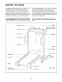
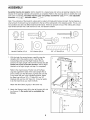
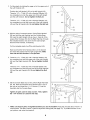
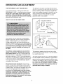
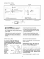
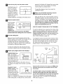
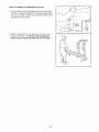
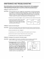
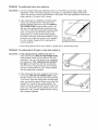
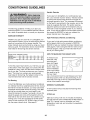
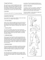
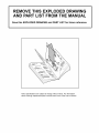
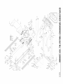
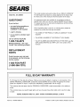
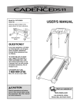
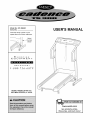
Model No. 831.294660
Serial No.
USER'S MANUAL
Write the serial number in the
space above for future reference.
Serial
Number
Decal
EXERCISE
EQ
U
I
P
M
E
NT
HELPLINE!
1-800-736-6879
SEARS, ROEBUCK AND CO.
HOFFMAN ESTATES, IL 60179
www.weslo.com
new products, prizes,
fitness tips, and much more!
TABLE OF CONTENTS
IMPORTANT PRECAUTIONS .............................................................
BEFORE YOU BEGIN ...................................................................
ASSEMBLY ...........................................................................
OPERATION AND ADJUSTMENT ..........................................................
HOW TO FOLD AND MOVE THE TREADMILL ...............................................
MAINTENANCE AND TROUBLE-SHOOTING
................................................
CONDITIONING GUIDELINES ...........................................................
ORDERING REPLACEMENT PARTS ...............................................
FULL 90-DAY WARRANTY
.......................................................
Note: An EXPLODED DRAWING and a PART LIST are attached in the center of this manual.
2
4
5
7
10
12
14
Back Cover
Back Cover
The decal shown below has been placed on your treadmill. If
the decal is missing, or if it is not legible, please call our tollfree HELPLINE to order a free replacement decal (see the
front cover of this manual). Apply the decal in the location
shown.
Note: The decal is shown at 38% of actual size.
BEFORE YOU BEGIN
Congratulations for selecting the new CADENCE ®TS
300 treadmill. The TS 300 treadmill combines
Monday through Saturday, 7 a.m. until 7 p.m. Central
Time (excluding holidays). To help us assist you,
please note the product model number and serial
number before calling. The model number of the treadmill is 831.294660. The serial number can be found on
advanced technology with innovative design to help
you get the most from your exercise in the convenience and privacy of your home. And when you're not
exercising, the unique TS 300 can be folded up, requiring less than half the floor space of other treadmills.
a decal attached to the treadmill (see the front cover of
this manual for the location).
For your benefit, read this manual carefully before
using the treadmill. If you have additional questions,
please call our toll-free HELPLINE at 1-800-736-6879,
Before reading further, please review the drawing
below and familiarize yourself with the parts that are
labeled.
Console
Speed Control
--
(Bottle
ater Bottle
not included)
Holder
Accessory Tray
Handrails
Key/Clip
Storage
Uprights
FRONT
.3ircuit Breaker
Power Cord
Walking Belt
Foot Rails
BACK
Pin
Rear Roller
Adjustment Bolts
RIGHT SIDE
Incline Leg
4
ASSEMBLY
Assembly requires two people. Set the treadmill in a cleared area and remove all packing materials. Do not
dispose of the packing materials until assembly is completed. Refer to the drawings below to identify the small
parts used in assembly. Assembly requires your own phillips screwdriver
_,
two adjustable
wrenches
_
, and wire cutters
,_._.
Note: The underside of the treadmill walking belt is coated with high-performance lubricant. During shipping, a
small amount of lubricant may be transferred to the top of the walking belt or the shipping carton. This is a normal condition and does not affect treadmill performance, tf there is lubricant on top of the walking belt, simply
wipe off the lubricant with a soft cloth and a mild, non-abrasive cleaner.
@
1 1/4" Screw (11)-4
3/8" Nut (61)-4
1/4" x 1" Bolt (42)-4_
Screw (2)-2
Handrail Washer (43)-4
3/8" Washer
3/8" x 2" Bolt (65)-4
(66)-4
1. With the help of a second person, carefully raise the
Uprights (46) to the position shown. Note that the
Console Base (52) and the Right Handrail (59) are
joined to the right Upright with the Wire Harness (60); be
careful not to pull on the Wire Harness. Set the Right
Handrail on the right Upright until step 3 is completed.
Refer to the inset drawing. Position one of the Base
Legs (62) against the base of the right Upright (46) as
shown. Make sure that the Base Leg Pads (63) and the
Front Wheel (68) are in the indicated positions. Attach
the Base Leg with two 3/8" x 2" Bolts (65), two 3/8"
Washers (66), and two 3/8" Nuts (61). It may be helpful
to tip the treadmill as you insert the Bolts.
52 _
_46
J
Attach the other Base Leg (62) in the same way.
68
2. Attach the Storage Latch (48) to the left Upright (46) with
two Screws (2). Be careful not to overtighten the
Screws.
I1148
5
qr--...63
65
3. Cut the plastic tie holding the cage nut in the upper end of
the Left Handrail (45).
Position the Left Handrail (45) on the left Upright (46).
Thread a 1/4" x 1" Bolt (42) with a Handrail Washer (43)
two complete turns into the upper end of the left Upright
and the Left Handrail. Do not tighten the Bolt yet.
Thread a 1/4" x 1" Bolt (42) with a Handrail Washer (43)
two complete turns into the lower end of the Left Handrail
(45) and the left Upright (46). Do not tighten the Bolt yet.
4. With the help of a second person, lift the Right Handrail
(59) and hold the right Handrail and the Console Base
(52) near the right Upright (46) as shown. Feed all of the
excess Wire Harness (60) into the Right Handrail, through
the indicated bracket, and down into the right Upright;
bend the Wire Harness, if necessary.
Cut the indicated plastic tie off the right Handrail (45).
Make sure that the Wire Harness (60) is in the bracket
and insert the bracket into the right Upright (46). Make
sure that the Wire Harness is not pinched.
5. Thread a 1/4" x 1" Bolt (42) with a Handrail Washer (43)
two complete turns into the upper end of the right Upright
(46) and the Right Handrail (59). Do not tighten the Bolt
yet.
Thread a 1/4" x 1" Bolt (42) with a Handrail Washer (43)
two complete turns into the lower end of the Right Handrail
(59) and the right Upright (45). Do not tighten the Bolt
yet.
6. Set the Console Base (52) on the Left and Right Handrails
(45, 59). Make sure that the Wire Harness (60) is out of
the way as you thread four 1 1/4" Screws (11) into the
Handrails and the Console Base.
Tighten all parts used in steps 3 and 5. Then, tighten
the 1 1/4" Screws (11) used in this step.
11
7. Make sure that all parts are tightened before you use the treadmill. Keep the included allen wrench in a
secure place. The allen wrench is used to adjust the walking belt (see page 13). To protect the floor or carpet, place a mat under the treadmill.
6
OPERATION AND ADJUSTMENT
THE PERFORMANT
LUBE TM WALKING BELT
Your treadmill features a walking belt coated with
PERFORMANT LUBE TM, a high-performance lubricant.
IMPORTANT: Never apply silicone spray or other
substances to the walking belt or the walking platform. Such substances will deteriorate the walking
belt and cause excessive wear.
This product is for use on a nominal 120-volt circuit,
and has a grounding plug that looks like the plug illustrated in drawing 1 below. A temporary adapter that
looks like the adapter illustrated in drawing 2 may be
used to connect the surge suppressor to a 2-pole
receptacle as shown in drawing 2 if a properly
grounded outlet is not available.
HOW TO PLUG IN THE POWER CORD
Outlet Box
Suppressor
Grounding Pin
Grounding Pin
Grounded Outlet
Grounding Plug
Outlet Box
Your treadmill, like any other type of sophisticated
electronic equipment, can be seriously damaged by
sudden voltage changes in your home's power.
Voltage surges, spikes, and noise interference can
result from weather conditions or from other appliances
being turned on or off. To decrease the possibility
of
your treadmill being damaged, always use a surge
suppressor with your treadmill (see drawing 1 at
the right).
To purchase a surge suppressor, see your local
SEARS or call toll-free 1-800-366-7278 and order
part number 146148. Use only a single-outlet surge
suppressor that is UL 1449 listed as a transient voltage surge suppressor (TVSS). The surge suppressor
must have a UL suppressed voltage rating of 400 volts
or less and a minimum surge dissipation of 450 joules.
The surge suppressor must be electrically rated for
120 volts AC and 15 amps.
This product must be grounded. If it should malfunction or break down, grounding provides a path of
least resistance for electric current to reduce the risk
of electric shock. This product is equipped with a cord
having an equipment-grounding conductor and a
grounding plug. Plug the power cord into a surge
suppressor, and plug the surge suppressor into an
appropriate outlet that is properly installed and
grounded in accordance with all local codes and
ordinances.Important:
The treadmill is not compatible with GFCI-equipped outlets.
Adapter
Metal Screw
The temporary adapter should be used only until a
properly grounded outlet (drawing 1) can be installed
by a qualified electrician.
The green-colored rigid ear, lug, or the like extending
from the adapter must be connected to a permanent
ground such as a properly grounded outlet box cover.
Whenever the adapter is used it must be held in place
by a metal screw. Some 2-pole receptacle outlet
box covers are not grounded. Contact a qualified
electrician to determine if the outlet box cover is
grounded before using an adapter.
DIAGRAM OF THE CONSOLE
Displays
Speed Control
SPI
i,
iNSERT
_S,£
d
KEY
ON
I RESE7
BU ITON
SLOW
[ STOP
CALS / FAT CALS / SPEED
TIME / DISTANCE
RgSET / SET SpEEZ3
_. WARNING:
HEART
To reduce
risk
of serious
before starfi_g treadmifl, read and unde_d
instructions,
and the warnings before use
injur_4
stand
on
foot
ra#s
_e user's manual _lJ
Keep children awa_
RATE
TRAINING
AEROBIC
165
ZONES
125
115
MA,_?BURN
145
130
12b
113
110
10.3
FATBURN
125
120
115
110
105
95
90
2O
30
4O
50
_0
7O
#tO
Age
15_
13R
145
140
130
L.._
CAUTION: Before
operating the
console, read the following
• Adjust the speed in small increments.
precautions.
• Do not stand on the walking belt when turning
on the power.
• Always wear the clip (see the drawing above)
while using the treadmill. When the key is
removed from the console, the walking belt
will stop.
• The training zones marked above the speed
control are general guidelines only. See page
14 for more information.
• To reduce the possibility of electric shock,
keep the console dry. Avoid spilling liquids on
the console. Use on ly a sealable water bottle.
BATTERY INSTALLATION
STEP BY STEP CONSOLE OPERATION
The console requires two "AA" batteries (not
included). Alkaline batteries are recommended.
To install batteries, open the battery cover under the
console as shown below. Press two batteries into the
battery compartment.
Make sure
that the negative (-)
ends of the
batteries are
touching the
springs.
Battery
Close the
Cover
battery cover.
If there is a thin sheet of clear film on the face of the
console, remove it.
Before operating the console, make sure that the
power cord is properly plugged in. (See HOW TO
PLUG IN THE POWER CORD on page 7.)
Next, step onto the foot rails of the treadmill. Find the
clip attached to the key (see the drawing above), and
slide the clip onto the waistband of your clothing. Test
the clip by carefully taking a few steps backward
until the key is pulled from the console. If the key
is not pulled from the console, adjust the position
of the clip as needed.
Follow the steps on page 9 to operate the console.
_l
Insert the key fully into the power switch.
Inserting the key will
not turn on the dis; "o
plays. The displays
will turn on when the
ON/RESET button is
pressed or when the
walking belt is started.
Note: If you just
installed batteries, the displays will already be on.
B
Reset the speed control.
Slide the speed
control to the
RESET
WARM=UP
FATBURN
Ab_
RESET position.
Note: Each
time the walk-
L ro,.
Jl
ing belt is
stopped, the
speed control must be moved to the RESET
position before the walking belt can be restarted.
IL_l Start the walking belt.
After you have moved the speed control to the
RESET position, slowly slide it to the right until the
walking belt begins to move at slow speed.
Carefully step onto the walking belt and begin
exercising. Change the speed of the walking belt
as desired by sliding the speed control.
seconds, the display will change from one number
to the next. Arrows in the display will indicate
which number is currently shown.
To reset the displays at any time, press the
ON/RESET button.
When you are finished exercising,
walking belt and remove the key.
Step onto the foot rails, slide the speed control to
the RESET position, and remove the key from the
console. The displays will turn off about five minutes after the key is removed. Note: Any time that
the walking belt is stopped and the ON/RESET
button is not pressed for five minutes, the displays will automatically turn off.
HOW TO CHANGE THE INCLINE OF THE TREADMILL
To vary the intensity of your exercise, the incline of the
treadmill can be changed. There are four incline levels.
Before changing the incline, remove the key and
unplug the power cord. Next, fold the treadmill to the
storage position (see HOW TO FOLD THE TREADMILL FOR STORAGE on page 10).
To change the incline, first remove the incline pin from
the right incline leg as shown below. Adjust the incline
leg to the desired height and fully reinsert the incline
pin. Make sure that the incline pin is in the "locked"
position shown in the inset drawing.
To stop the walking belt, step onto the foot rails
and slide the speed control to the RESET position.
B
stop the
Incline
Monitor your progress with the two displays.
TIME/DISTANCE disArrow
play--This display
shows the elapsed time
and distance that you
have walked or run, in
TIME / DISTANCE
miles. Every seven seconds, the display will
change from one number to the other. Arrows in
the display will indicate which number is currently
shown.
CALS/FAT CALS/
Arrow
SPEED display--This
display shows the
approximate numbers
of calories and fat caloCALS I FAT CALS I SPEED
ries you have burned.
(See FAT BURNING on
page 14.) In addition, the display shows the speed
of the walking belt, in miles per hour. Every seven
Incline
Pin
Right
Leg
Adjust the left incline leg in the same way. Make sure
that both incline pins are inserted from the direction shown.
CAUTION: Before using the treadmill, make sure
that both incline legs are at the same height. Do
not use the treadmill with the incline pins removed.
After you have adjusted the incline legs, lower the
treadmill (see HOW TO LOWER THE TREADMILL
FOR USE on page 11).
HOW TO FOLD AND MOVE THE TREADMILL
HOW TO FOLD THE TREADMILL
FOR STORAGE
Before folding the treadmill, unplug the power cord.
CAUTION: You must be able to safely lift 45 pounds (20
kg) in order to raise, lower or move the treadmill.
1. Hold the treadmill with your hands in the locations shown
at the right. To decrease the possibility of injury, bend
your legs and keep your back straight. As you raise
the treadmill, make sure to lift with your legs rather
than your back. Raise the treadmill about halfway to the
vertical position.
2. Move your right hand to the position shown and hold the
treadmill firmly. Raise the treadmill until the storage latch
closes over the catch. Make sure that the storage latch
is fully engaged over the catch.
To protect the floor or carpet from damage, place a
mat under the treadmill. Keep the treadmill out of
direct sunlight. Do not leave the treadmill in the storage position in temperatures above 85 ° Fahrenheit.
HOW TO MOVE THE TREADMILL
Before moving the treadmill, convert the treadmill to the
storage position as described above. Make sure that the
storage latch is locked fully over the catch.
1. Hold the upper ends of the handrails. Place one foot on
one of the front wheels as shown.
2. Tilt the treadmill back until it rolls freely on the front
wheels. Carefully move the treadmill to the desired location. To reduce the risk of injury, use extreme caution
while moving the treadmill. Do not attempt to move
the treadmill over an uneven surface.
3. Place one foot on the base, and carefully lower the treadmill until it is resting in the storage position.
10
Base
Leg
Front
Wheels
HOW TO LOWER THE TREADMILL
FOR USE
1. Hold the upper end of the treadmill with your right hand
as shown. Using your left thumb, press the storage latch
and hold it. Pivot the treadmill until the frame and foot rail
are past the storage latch.
2. Hold the treadmill firmly with both hands, and lower the
treadmill to the floor. To decrease the possibility of
injury, bend your legs and keep your back straight.
11
MAINTENANCE
AND TROUBLE-SHOOTING
Most treadmill problems can be solved by following the simple steps below. Find the symptom that
applies, and follow the steps listed. If further assistance is needed, call our toll-free HELPLINE at
1-800-736-6879, Monday through Saturday, 7 a.m. until 7 p.m. Central Time (excluding holidays).
PROBLEM:
The power does not turn on
SOLUTION: a. Make sure that the power cord is plugged into a surge suppressor, and that the surge suppressor is plugged into a properly grounded outlet (see page 7). Use only a single-outlet surge suppressor that is UL 1449 listed as a transient voltage surge suppressor (TVSS). The surge suppressor must have a UL suppressed voltage rating of 400 volts or less and a minimum surge
dissipation of 450 joules. The surge suppressor must be electrically rated for 120 volts AC and
15 amps. Important: The treadmill is not compatible with GFCl-equipped outlets.
b. After the power cord has been plugged in, make sure that the key is fully inserted into the console.
Check the circuit breaker located on the treadmill
frame near the power cord. If the switch protrudes as shown, the circuit breaker has tripped.
To reset the circuit breaker, wait for five minutes
and then press the switch back in.
PROBLEM:
C
Reset
Tripped
The power turns off during use
SOLUTION: a. Check the circuit breaker located on the treadmill frame near the power cord (see the drawing
above). If the circuit breaker has tripped, wait for five minutes and then press the switch back in.
b. Make sure that the power cord is plugged in.
c. Unplug the power cord, wait for five minutes, and then plug the power cord back in.
d. Remove the key from the console. Reinsert the key fully into the console.
e. If the treadmill still will not run, please call our toll-free HELPLINE.
PROBLEM:
The displays of the console do not function
properly
SOLUTION:
a. Check the batteries in the console. If the batteries need to be replaced, see BATTERY
INSTALLATION on page 8. Most problems are the result of drained batteries.
Remove the key from the console and UNPLUG
THE POWER CORD. Remove the screws from the
hood. Carefully remove the hood. Locate the Reed
Switch (76) and the Magnet (47) on the left side of
the Pulley (77). Turn the Pulley until the Magnet is
aligned with the Reed Switch. Make sure that the
gap between the Magnet and the Reed Switch is
about 1/8". If necessary, loosen the Screw (17) and
move the Reed Switch slightly. Retighten the Screw.
Re-attach the hood, and run the treadmill for a few
minutes to check for a correct speed reading.
12
,
17_
76----__
1/8"
Top View
77
PROBLEM:
The walking belt slows when walked on
SOLUTION: a. Use only a single-outlet surge suppressor that is UL 1449 listed as a transient voltage surge
suppressor (TVSS). The surge suppressor must have a UL suppressed voltage rating of 400
volts or less and a minimum surge dissipation of 450 joules. The surge suppressor must be electrically rated for 120 volts AC and 15 amps.
b.
If the walking belt is overtightened, treadmill performance may decrease and the walking belt may
become damaged. Remove the key and UNPLUG
THE POWER CORD. Using the allen wrench, turn
both rear roller adjustment bolts counterclockwise,
1/4 of a turn. When the walking belt is properly tightened, you should be able to lift each side of the
walking belt 2 to 3 inches off the walking platform.
Be careful to keep the walking belt centered. Plug in
the power cord, insert the key and run the treadmill
for a few minutes. Repeat until the walking belt is
properly tightened.
Rear Roller
Adjustment Bolts
c. If the walking belt still slows when walked on, please call our toll-free HELPLINE
PROBLEM:
The walking belt is off-center or slips when walked on
SOLUTION: a. If the walking belt has shifted to the left, first
remove the key and UNPLUG THE POWER CORD.
Using the allen wrench, turn the left rear roller bolt
clockwise 1/2 of a turn. Be careful not to overtighten
the walking belt. If the walking belt has shifted to
the right, turn the left rear roller bolt counterclockwise 1/2 of a turn. Plug in the power cord, insert the
key and run the treadmill for a few minutes. Repeat
until the walking belt is centered.
b.
If the walking belt slips when walked on, first remove
the key and UNPLUG THE POWER CORD. Using
the allen wrench, turn both rear roller bolts clockwise,
1/4 of a turn. When the walking belt is correctly tightened, you should be able to lift each side of the walking belt 2 to 3 inches off the walking platform. Be
careful to keep the walking belt centered. Plug in the
power cord, insert the key and carefully walk on the
treadmill for a few minutes. Repeat until the walking
belt is properly tightened.
13
CONDITIONING
GUIDELINES
Aerobic Exercise
If your goal is to strengthen your cardiovascular system, your exercise must be "aerobic." Aerobic exercise
is activity that requires large amounts of oxygen for
prolonged periods of time. This increases the demand
on the heart to pump blood to the muscles, and on the
lungs to oxygenate the blood. For aerobic exercise,
adjust the speed and incline of the treadmill until your
heart rate is near the highest number in your training
zone. It may also be helpful to set the speed control on
the console to AEROBIC to help you maintain the
proper intensity level. (See page 9.)
The following guidelines will help you to plan your
exercise program. For more detailed exercise information, obtain a reputable book or consult your physician.
EXERCISE INTENSITY
High Performance Athletic Conditioning
Whether your goal is to burn fat or to strengthen your
cardiovascular system, the key to achieving the desired
results is to exercise with the proper intensity. The
proper intensity level can be found by using your heart
rate as a guide. The chart below shows recommended
heart rates for fat burning and aerobic exercise.
HEART RATE TRAINING
HOW TO MEASURE YOUR HEART RATE
ZONES
AEROBIC
165
155
145
140
130
125
115
MAXFATBURN
145
138
130
125
113
110
103
FATBURN
125
120
115
110
105
95
90
20
30
40
50
60
70
80
Age
If your goal is high performance athletic conditioning,
set the speed control on the console to PERFORMANCE to help you maintain the proper intensity level.
(See page 9.) Note: During the first few weeks of your
exercise program, keep your heart rate near the low
end of your training zone.
To measure your
heart rate, stop
exercising and
place two fingers
on your wrist as
shown. Take a sixsecond heartbeat
count, and multiply
the result by ten to
find your heart
rate. (A six-second count is used because your heart
rate drops quickly when you stop exercising.) If your
heart rate is too high or too low, adjust the speed or
incline of the treadmill accordingly.
To find the proper heart rate for you, first find your age
at the bottom of the chart (ages are rounded off to the
nearest ten years). Next, find the three numbers at the
top of your age. The three numbers are your "training
zone." The lower two numbers are recommended
heart rates for fat burning; the highest number is the
recommended heart rate for aerobic exercise.
Fat Burning
To burn fat effectively, you must exercise at a relatively
low intensity level for a sustained period of time. During
the first few minutes of exercise, your body uses easily
accessible carbohydrate calories for energy. Only after
the first few minutes does your body begin to use
stored fat calories for energy. If your goal is to burn fat,
adjust the speed and incline of the treadmill until your
heart rate is near one of the lower two numbers in your
training zone. tt may also be helpful to set the speed
control on the console to FAT BURN to help you maintain the proper intensity level. (See page 9.)
WORKOUT
GUIDELINES
A well-rounded workout includes the following three
important parts:
A Warm-up
Start each workout with 5 to 10 minutes of stretching
and light exercise (see SUGGESTED STRETCHES on
page 15). A proper warm-up increases your body
temperature, heart rate, and circulation in preparation
for exercise.
14
Training Zone Exercise
to cool down. This will increase the flexibility of your
muscles and will help to prevent post-exercise problems.
After warming up, increase the intensity of your exercise until your pulse is in your training zone for 20 to
60 minutes. (During the first few weeks of your exercise program, do not keep your pulse in your training
zone for longer than 20 minutes.) Breathe regularly
and deeply as you exercise--never
hold your breath.
EXERCISE FREQUENCY
To maintain or improve your condition, complete three
workouts each week, with at least one day of rest
between workouts. After a few months, you may complete up to five workouts each week if desired.
A Cool-down
The key to success is to make exercise a regular and
enjoyable part of your everyday life.
Finish each workout with 5 to 10 minutes of stretching
SUGGESTED
STRETCHES
The correct form for several basic stretches is shown at the right.
Move slowly as you stretch--never bounce.
1. Toe Touch Stretch
Stand with your knees bent slightly and slowly bend forward from
your hips. Allow your back and shoulders to relax as you reach
down toward your toes as far as possible. Hold for 15 counts, then
relax. Repeat 3 times. Stretches: Hamstrings, back of knees, and
back.
2. Hamstring
Stretch
Sit with one leg extended. Bring the sole of the opposite foot
toward you and rest it against the inner thigh of your extended leg.
Reach toward your toes as far as possible. Hold for 15 counts,
then relax. Repeat 3 times for each leg. Stretches: Hamstrings,
lower back, and groin.
3. Calf/Achilles
Stretch
With one leg in front of the other, reach forward and place your
hands against a wall. Keep your back leg straight and your back
foot flat on the floor. Bend your front leg, lean forward and move
your hips toward the wall. Hold for 15 counts, then relax. Repeat 3
times for each leg. To cause further stretching of the achilles tendons, bend your back leg as well. Stretches: Calves, achilles tendons, and ankles.
4. Quadriceps Stretch
With one hand against a wall for balance, reach back and grasp
one foot with your other hand. Bring your heel as close to your
buttocks as possible. Hold for 15 counts, then relax. Repeat 3
times for both legs. Stretches: Quadriceps and hip muscles.
5. Inner Thigh Stretch
Sit with the soles of your feet together and your knees outward.
Pull your feet toward your groin area as far as possible. Hold for
15 counts, then relax. Repeat 3 times. Stretches: Quadriceps and
hip muscles.
15
2
REMOVE THIS EXPLODED DRAWING
AND PART LIST FROM THE MANUAL
Save this EXPLODED
DRAWING
and PART LIST for future
Note: Specifications are subject to change without notice. For information
about ordering replacement parts, see the back cover of the User's Manual.
reference.
PART LIST--Model
1
2
3
4
5
6
7
8
9
10
11
12
13
14
15
1
16
20
5
1
1
1
2
4
6
4
2
1
2
4
16
17
18
19
20
21"
22
23
24
25
26
27
28
29
30
31
32
33
34
35
36
37
38
39
40
41
42
43
44
45
46
No. 831.294660
R0801A
Motor Hood
Screw
3/4" Screw
8" Cable Tie
Cable Tie
Clamp Screw
Cable Tie Clamp
Foot Rail
Platform Isolator
Platform Screw
1 1/4" Screw
Incline Leg Washer
Catch
Belt Guide
Belt Guide Screw
47
48
49
50
51
52
53
54
55*
56
57
58
59
60
61
1
1
1
1
1
1
1
1
1
1
1
1
1
1
8
Magnet
Storage Latch
Left Endcap
Ground Wire
Key/Clip
Console Base
Console Plug
Battery Cover
Console Assembly
Speed Potentiometer
Console
Upright Grommet
Right Handrail
Wire Harness
3/8" Nut
1
1
4
1
1
1
1
1
1
2
1
2
1
3
1
Reed Switch Clip
Reed Switch Screw
Hood Anchor
Motor
Pulley/Flywheel/Fan
MotorlPulleylFlywheellFan
Motor Tension Bolt
Motor Tension Washer
Motor Star Washer
Motor Tension Nut
Motor Pivot Bolt
Frame Spacer
Power Cord Grommet
Wire Clip
Power Cord
62
63
64
65
66
67
68
69
70
71
72
73
74
75
76
2
4
1
4
6
2
2
1
2
2
1
1
1
1
1
Base Leg
Base Leg Pad
Allen Wrench
3/8 x 2" Bolt
3/8" Washer
Wheel Bolt
Wheel
Speed Control Knob
Frame Pivot Bolt
Frame Pivot Washer
Walking Belt
Belly pan
Walking Board
Warning Decal
Reed Switch/Sensor Wire
1
8
1
2
1
1
2
3
1
2
1
4
4
2
2
1
Controller
Electronic Screw
Choke
Bracket Screw
Electronics Bracket
Circuit Breaker
Base Leg Endcap
Roller Adjustment Washer
Front Roller Adjustment Bolt
Plastic Fastener
Motor Belt
1/4 x 1" Bolt
Handrail Washer
Cage Nut
Left Handrail
Upright Base
77
78
79
80
81
82
83
84
85
86
#
#
1
1
1
2
2
2
1
2
1
2
1
1
Drive Roller/Pulley
Frame Guide
Frame
Incline Pin
Incline Leg
Incline Leg Cap
Right Endcap
Roller Guard
Rear Roller
Rear Roller Adjustment Bolt
8" White Wire, Male/Female
User's Manual
* Includes all parts shown in the box
Note: "#" indicates a non-illustrated part.
Specifications are subject to change without notice. See the back cover of the user's manual for information
about ordering replacement parts.
m
X
r-
0
52
1
0
m
2
0
0
/
2
\
/
/
"_,_/,,,"
60
2
2
42
39
&
43
Z
0
59
38
70
00
27
3
6I
71
70
37
0
66
61
_63
_3
/
67
_63
_3
65
0
O0
0
3>
SEARS
The model number and serial number of your WESLO CADENCE _
TS 300 treadmill are listed on a decal attached to the frame. See
the front cover of this manual to find the location of the decal.
Model No 831 294660
QUESTIONS?
All replacement parts are available for immediate purchase or
special order when you visit your nearest SEARS Service Center.
To request service or to order parts by telephone, call the toll-free
numbers listed at the left.
If you find that:
• you need help assembling or
operating the WESLO
CADENCE TS 300 treadmill
• a part is missing
• or you need to schedule repair
service
When requesting help or service, or ordering parts, please be
prepared to provide the following information:
• The NAME OF THE PRODUCT (WESLO CADENCE ®TS 300
treadmill)
• The MODEL NUMBER OF THE PRODUCT (831.294660)
call our toll-free HELPLINE
1-800-736-6879
Monday-Saturday,
7 am-7 pm
Central Time (excluding holidays)
• The KEY NUMBER AND DESCRIPTION OF THE PART (see the
EXPLODED DRAWING and PART LIST in the center of this
manual).
REPLACEMENT
PARTS
If parts become worn and need
to be replaced, call the following
toll-free number
1-800-FON-PART
(1-800-366-7278)
FULL 90 DAY WARRANTY
For 90 days from the date of purchase, if failure occurs due to defect in material or workmanship in this
SEARS TREADMILL EXERCISER, contact the nearest SEARS Service Center throughout the United
States and SEARS will repair or replace the TREADMILL EXERCISER, free of charge.
This warranty does not apply when the TREADMILL EXERCISER is used commercially or for rental purposes.
This warranty gives you specific legal rights, and you may also have other rights which vary from state
to state.
SEARS, ROEBUCK AND CO., DEPT 817WA, HOFFMAN ESTATES, IL 60179
Part No. 176440 R0801A
Printed in USA © 2001 Sears, Roebuck and Co.