1
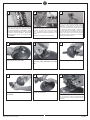
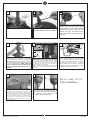
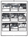
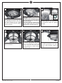
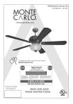
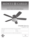
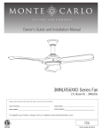
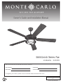
Owner’s Guide and Installation Manual
5BR52XXD Series Fan
UL Model No. : AC-552OD
Attach sales receipt to this card and retain as your proof of purchase
DATE OF PURCHASE:
RETAILER NAME:
MODEL NUMBER:
RETAILER ADDRESS:
To register your fixture, please visit our website www.montecarlofans.com
8.6 kgs
18.92 lbs
Total fan weight with light kit
Cautions and Warnings
WARNING: TO REDUCE THE RISK OF FIRE, ELECTRIC SHOCK, OR INJURY TO PERSONS, OBSERVETHE FOLLOWING
READ AND SAVE THESE INSTRUCTIONS
Installation work and electrical wiring must be done by qualified person(s) in accordance with applicable codes and standards (ANSI/NFPA
70-1999), including fire-rated construction.
Use this unit only in the manner intended by the manufacturer. If you have any questions contact the manufacturer.
After making the wire connections, the wires should be spread apart with the grounded conductor and the equipment-grounding conductor on one side of the outlet box and ungrounded conductor on the other side of the outlet box. The splices, after being made, should be
turned upward and pushed carefully up into the outlet box.
WARNING: Before you begin installing the fan, servicing or cleaning unit, Switch power off at Service panel and lock service disconnecting
means to prevent power from being switched on accidentally. When the service disconnecting means cannot be locked, securely fasten a
prominent warning device, such as a tag, to the service panel.
Be cautious! read all instructions and safety information before installing your new fan. Review the accompanying assembly diagrams.
When cutting or drilling into wall or ceiling, do not damage electrical wiring and other hidden utilities.
Make sure the installation site you choose allows the fan blades to rotate without any obstructions. Allow a minimum clearance of 7 feet
from the floor to the trailing edge of the blade.
WARNING: To Reduce The Risk Of Fire, Electric Shock, or Personal Injury, Mount To Outlet Box Marked “Acceptable for Fan Support of 15.9
kg (35 lbs) or less” And Use Mounting Screws Provided With The Outlet Box.
CAUTION: For Compliance with Local Codes and Regulations, If Installing The Secondary Support Safety Cable in the U.S., Do Not Remove
Knockouts In The Outlet Box. Mount the secondary support safety cable through the reserved nail/screw hole on the outlet box to the
building structure (or the ceiling joist).
WARNING: To reduce the risk of personal injury, do not bend blade holders during installation to motor, balancing or during cleaning. Do
not insert foreign object between rotating blades.
Attach the mounting bracket using only the hardware supplied with the outlet box.
WARNING: To reduce the risk of fire or electric shock, this fan must be installed with an isolating wall control/switch.
WARNING: To reduce the risk of fire or electric shock, do not use this fan with any solid state fan speed control device, or variable speed
control.
If this unit is to be installed over a tub or shower, it must be marked as appropriate for the application.
Never place a switch where it can be reached from a tub or shower.
The combustion airflow needed for safe operation of fuel-burning equipment may be affected by this unit’s operation. Follow the heating
equipment manufacturer’s guideline safety standards such as those published by the National Fire Protection Association (NFPA), and the
American Society for Heating, Refrigeration and Air Conditioning Engineers (ASHRAE) and the local code authorities.
CAUTION: To Reduce the Risk of Electric Shock, Disconnect the electrical supply circuit to the fan before installing the light kit.
All set screws must be checked and tightened where necessary before installation.
Note: Suitable for use in wet locations when installed in a GFCI protected branch circuit.
Tools Required for Assembly (not included): Electrical Tape, Phillips Screwdriver, Pliers, Safety Glasses, Stepladder and Wire Strippers
Customer Service
800-969-3347
Customer Service Center
7400 Linder Ave.
Skokie, IL 60077
www.montecarlofans.com
© 2013 Monte Carlo Fan Company
2
7/1/2013
1
2
Before you begin installing the fan, Switch
power off at Service panel and lock service
disconnecting means to prevent power
from being switched on accidentally. When
the service disconnecting means cannot
be locked, securely fasten a prominent
warning device, such as a tag, to the
service panel.
4
Downrod Mount Installation
Loosen 2 screws on yoke to allow
down rod to slip into yoke.
7
Place yoke cover over downrod
as shown.
© 2013 Monte Carlo Fan Company
3
Before installing this fan make sure the
outlet box is properly installed to the house
structure. To reduce the risk of fire, electric
shock, or personal injury, mount to outlet
box or supporting system acceptable for fan
support.
(Mounting must support at least 35 lbs.)
5
Use metal outlet box suitable for fan support
and use only the screws provided with the
outlet box (must support 35 lbs). Before
attaching fan to outlet box, ensure the outlet
box is securely fastened by at least two points
to a structural ceiling member ( a loose box
will cause the fan to wobble). Remove the
two outlet box screws provided with the box,
aligning the holes of the mounting bracket
with the holes of the outlet box. Re-install the
2 outlet box screws securely.
6
Remove keeper pin and cross
pin from yoke, and save for later
use.
8
Place canopy over downrod.
9
Thread the leadwires and safety cable
through the downrod.
3
Insert downrod into the yoke on top of fan
body. Align the hole in the downrod with the
hole in the yoke. Insert cross pin through
yoke and downrod until point appears on the
other side.
7/1/2013
10
11
12
Install keeper pin.
Tighten 2 set screws on yoke
once the down rod is in place.
Loosen two preassembled
screws across from each other
corresponding to the open slotted
holes on the canopy upper rim and
remove the other two screws from
mounting bracket. Keep screws for
later use.
13
14 Safety cable installation
15
Safety cable
Supply
circuit
Lag screw
Lag screw
Safety cable
Washer
Lock washer
Hang assembled fan from the mounting
bracket installed to ceiling in previous
step. Make sure the fan is hanging
straight. Rotate fan until the tab on
the Mounting bracket engages the slot
on the Downrod Ball. This must be
done to prevent the fan body from
rotating when the blades are in
motion.
For Canadian installation and for USA fan and light
kit combinations over 35 lbs, in both flush and
downrod mode the safety cable must be installed
into the house structure beams using the 3” lag
screws,washers, and lock washers. provided. Make
sure that when the safety cable is fully extended
the leadwires are longer than the cable and no
stress is placed on the leadwires.
Note: If Installing The Secondary Support Safety
Cable in the U.S., Do Not Remove Knockouts In The
Outlet Box.
16
17
Make wiring connections as indicated
above. Connect black and blue wire from
fan to Black or (Hot) wire from house.
Connect White wire from Fan to White
(Neutral) wire from house. Connect
Ground leads from mounting bracket and
downrod to Ground lead from house. Refer
to Safety Tips section of manual.
Go to step 27 to
finish installation
Make wire connections to power source using
wire nuts provided. Make sure that no filiments
are outside of the wirenut. After making the wire
connections, the wires should be spread apart
with the grounded conductor and the equipmentgrounding conductor on one side of the outlet
box and ungrounded conductor on the other side
of the outlet box. The splices after being made
should be turned upward and pushed carefully up
into the outlet box.
© 2013 Monte Carlo Fan Company
Lift canopy up, aligning its keyhole
slots with the preassembled screw on
mounting bracket and twist clockwise till
lock. Install the screw removed in step
12. Tighten all screws securely.
4
7/1/2013
18 Flushmount Installation
19
20
Re m o v e c a n o p y b o t t o m c o v e r
from canopy by twisting
counterclockwise.
Remove set screws and pins from
yoke as inset shown.
Remove every other screw as
circled and save screws for
later use.
Pass leadwires and safety
cable through canopy.
Place the canopy over the yoke
screws, aligning the large holes
from the canopy over the screws
on the yoke. Re-install the 3 screws
removed in step 19 to secure the
canopy.
21
22
Hand free
hook
23 Safety cable installation
Safety cable
Lag screw
Lag screw
Safety cable
Washer
Lock washer
Loosen two preassembled
screws across from each other
corresponding to the open slotted
holes on the canopy upper rim and
remove the other two screws from
mounting bracket. Keep screws for
later use.
Hang fan from mounting
bracket by the hands free
hook into a closed hole on
the edge of the Canopy.
24
25
26
Make wire connections to power source using
wire nuts provided. Make sure that no filiments
are outside of the wirenut. After making the wire
connections, the wires should be spread apart
with the grounded conductor and the equipmentgrounding conductor on one side of the outlet
box and ungrounded conductor on the other side
of the outlet box. The splices after being made
should be turned upward and pushed carefully up
into the outlet box.
Lift fan to mounting bracket,
aligning the “L” shape holes with
the scresws on the mounting
bracket. Turn the fan clockwise
to lock in position. Re-nstall
the 2 canopy mounting bracket
screws removed in step 21.
For Canadian installation and for USA fan and light
kit combinations over 35 lbs, in both flush and
downrod mode the safety cable must be installed
into the house structure beams using the 3” lag
screws,washers, and lock washers. provided. Make
sure that when the safety cable is fully extended the
leadwires are longer than the cable and no stress
is placed on the leadwires. Note: If Installing The
Secondary Support Safety Cable in the U.S., Do Not
Remove Knockouts In The Outlet Box.
Supply
circuit
Make wiring connections as indicated
above.Connect black and blue wire from
fan to Black or (Hot) wire from house.
Connect White wire from Fan to White
(Neutral) wire from house. Connect
Ground leads from mounting bracket
to Ground lead from house. Refer to
Safety Tips section of manual.
© 2013 Monte Carlo Fan Company
5
7/1/2013
27
Place blade bracket onto blade
by aligning the 3 holes on blade
as shown.
28
29
Shipping
stabilizer
Install blade bracket with blade by
3 blade screws provided. Tighten
securely. Repeat this process for
remaining blades.
Check motor for shipping stabilizers
and remove if present. Install the blade
assembly to motor using the screws
pre-installed. Tighten screws securely.
Repeat this process for remaining blade
assemblies.
30
31
32
Loosen 3 and remove 1 preassembled
scews from the plate on motor. Save
screw for later use.
Place light pan over wires from motor.
Attached light pan on to the plate on
motor, aligning the keyhole slots with
the preassembled screws on the plate.
Twist clockwise till lock. Install the screw
removed in step 30. Tighten all screws
securely.
Connect plug from fan to plug
from light pan. Make sure the
plugs are hooked together.
33
34
35
Attach capacitor and wattage
limiter onto light pan by
preadhered double-sided foam
tap as shown.
© 2013 Monte Carlo Fan Company
Loosen 2 and remove 1
preassembled screw from
the light pan. Save screw for
later use.
6
Hook
Remove finial and screw nut from
light fixture.
Connect white wire from light pan
to white wire from light fixture.
Connect blue wire from light pan to
black wire from lighgt fixture.
7/1/2013
38
36
37
Attached light fixture on to the light
pan, aligning the keyhole slots with
the preassembled screws on the light
pan. Twist clockwise till lock. Install
the screw removed in step 34. Tighten
all screws securely.
Install 3 x 40-watt candelabra base
bulbs. Bulbs included.
WARNING: Over lamping the fan
will result in the fan lights shutting
down until the proper wattage of
bulbs are installed.
Reset the lights by turning off,
replace bulbs with the correct
wattage bulbs, turn the power on.
39
40
41
Install the finial removed in step
35 to secure the bottom cage with
glass. Corresponding to step 41
to make sure pull chain align with
knurled grommet on light fixture,
and bottom cage.
Place pull chains through the
knurled grommet on light
fixture, and bottom cage as
shown.
Attached bottom cage onto
glass as shown.
© 2013 Monte Carlo Fan Company
7
This side up
Place glass over the threaded
rod and secure it by the screw
nut removed in step 35. Tigthen
securely.
7/1/2013
Trouble Shooting
If you have difficulty operating your new ceiling fan, it may be the result of incorrect assembly, installation,
or wiring. In some cases, these installation errors may be mistaken for defects. If you experience any faults,
please check this Trouble Shooting Chart. If a problem cannot be remedied, or you are experiencing difficulty in
installation, please call our Customer Service Center at the
number printed on your parts list insert sheet.
Warning: Before servicing or cleaning unit, Switch power off at Service panel and lock service disconnecting
means to prevent power from being switched on accidentally. When the service disconnecting means cannot be
locked, securely fasten a prominent warning device, such as a tag, to the service panel.
Trouble
Suggested Remedy
1. If fan does not start:
1.Check main and branch circuit fuses or circuit breakers.
2.Check line wire connections to fan and switch wire connections in switch housing.
CAUTION: Make sure main power is turned off.
3.If this fan uses manual forward/reverse switch, make sure the switch is pushed firmly
either way. Fan will not operate when switch is in the middle.
4.If this fan uses remote controller, make sure dip switches are setting properly and make
sure battery is effective.
2. If fan sounds noisy:
1.Check to make sure all screws in motor housing are snug (not over tightened).
2.Check to make sure the screws which attach the fan blade holder to the motor are tight.
3.Check to make sure wire nut connectors in switch housing are not rattling against each
other or against the interior wall of the switch housing.
CAUTION: Make sure main power is turned off before entering switch housing.
4.Check to be sure light bulb is tight in socket and not touching the glass shade.
5.Some fan motors are sensitive to signals from Solid State variable speed controls.
6.Allow "break-in" period of 24 hours. Most noises associated with a new fan will disappear
after this period.
3. If fan wobbles:
1.If this is a downrod mount fan, make sure the ridge on mounting bracket engages the
notch in the downrod ball.
2.Make sure that canopy, mounting bracket or mounting plate are tightened securely to
ceiling junction box and junction box is mounted firmly to ceiling joist.
3.Check that all blades are screwed firmly into blade holders.
4.Check that all blade holders are tightened securely to motor.
5.Most fan wobble problems are caused when blade levels are unequal. Check this level by
selecting a point on the ceiling above the tip of one of the blades. Measure this distance
from blade tip to ceilng. Keeping measure within 1/8", rotate the fan until the next blade
is positioned for measurement. Repeat for each blade. If all blade levels are not equal,
you can adjust blade levels by the following procedure. To adjust a blade tip down, insert
a washer (not supplied) between the blade and blade holder at the screw closest to the
motor. To adjust a blade tip up, insert washer (not supplied) between the blade and blade
holder at the two screws farthest from the motor. Reverse the position of the washer if
blades mount from top of blade.
6.If blade wobble is still noticeable, interchanging two adjacent (side by side) blades can
redistribute the weight and possibly result in smoother operation.
4. If light does not work: 1.Check blue wire from fan to make sure it is connected to hot wire from house.
2.Check for loose or disconnected wires in fan switch housing.
3.Check for loose or disconnected wires in light kit.
4.Check for faulty light bulb and make sure bulb is tight in socket.
5.Remove light kit and check the plug connections if they are present.
6.If this fan uses remote controller, make sure dip switches are setting properly and make
sure battery is effective.
CAUTION: Make sure main power is turned off before entering switch housing and/or
canopy.
WARNING: Over lamping the fan will result in the fan lights shutting down until the proper
wattage of bulbs are installed. Reset the lights by turning off, replace bulbs with the correct
wattage bulbs, Turn power on.
© 2013 Monte Carlo Fan Company
8
7/1/2013
Mar.2012 New format
Jul.2013 Update for CUL regulation