1
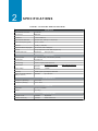
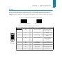
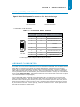
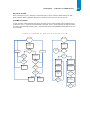
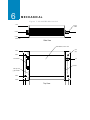
NL900PRO
User Manual
Version B0
Radio Data Modem
With Selectable
RS232 RS485 RS422
7610 MIRAMAR ROAD
San Diego, CA 92126
(800) 233-1728
www.rfneulink.com
[email protected]
DOCUMENT INFORMATION
Copyright © 2013 Raveon Technologies
The information contained in this manual and the accompanying software programs are copyrighted and all
rights are reserved by Raveon Technologies Corporation. Raveon reserves the right to make periodic
modifications of this product without obligation to notify any person or entity of such revision. Copying,
duplicating, selling, or otherwise distributing any part of this product or accompanying
documentation/software without the prior consent of an authorized representative of Raveon is strictly
prohibited.
All brands and product names in this publication are registered trademarks or trademarks of their respective
holders.
This material is preliminary
Information furnished by Raveon Technologies in this specification is believed to be accurate. Devices
sold by Raveon Technologies are covered by the warranty and patent indemnification provisions appearing in
its Terms of Sale only. Raveon Technologies makes no warranty, express, statutory, and implied or by
description, regarding the information set forth herein. Raveon Technologies reserves the right to change
specifications at any time and without notice.
Raveon Technologies’ products are intended for use in normal commercial and industrial applications.
Applications requiring unusual environmental requirements such as military, medical life-support or
life-sustaining equipment are specifically not recommended without additional testing for such application.
Limited Warranty, Disclaimer, Limitation of Liability
For a period of one (1) year from the date of purchase by the OEM customer, Raveon Technologies warrants
the OEM transceiver against defects in materials and workmanship. Raveon Technologies will not honor this
warranty (and this warranty will be automatically void) if there has been any (1) tampering, signs of
tampering; 2) repair or attempt to repair by anyone other than an Raveon Technologies authorized technician.
This warranty does not cover and Raveon Technologies will not be liable for, any damage or failure caused by
misuse, abuse, acts of God, accidents, electrical irregularity, or other causes beyond Raveon Technologies’
control, or claim by other than the original purchaser.
In no event shall Raveon Technologies be responsible or liable for any damages arising: From the use of
product; From the loss of use, revenue or profit of the product; or As a result of any event, circumstance,
action, or abuse beyond the control of Raveon Technologies, whether such damages be direct, indirect,
consequential, special or otherwise and whether such damages are incurred by the person to whom this
warranty extends or third party.
If, after inspection, Raveon Technologies determines that there is a defect, Raveon Technologies will repair or
replace the OEM
transceiver at their discretion. If the product is replaced, it may be a new or refurbished product.
1
NL900PRO RF TRANSCEIVER 1
The NL900PRO transceiver is a Frequency-Hopping Spread Spectrum (FHSS) radio designed for license-free
operation in the 900 MHz ISM band. The radio sustains a standard asynchronous serial data stream
between two or more radios out of the box. Housed in a compact and rugged die-cast enclosure, the radio
is equipped to replace miles of serial cable using a selectable RS232, RS485, or RS422 interface.
NL900PRO FEATURES
NETWORKING AND SECURITY
•
Retries and Acknowledgements
•
API Commands to control packet routing and acknowledgement on a packet-by-packet basis
•
Frequency Hopping Spread Spectrum for security and interference rejection
•
Customizable RF Channel number and system ID
•
Dynamic link analysis, remote radio discovery
•
Low latency and high throughput
EASY TO USE
•
Continuous 76.8 kbps RF data stream
•
Software selectable interface baud rates from 1200 bps to 115.2 kbps
•
Advanced configuration available using AT commands
OVERVIEW
The NL900PRO uses Frequency Hopping Spread Spectrum modulation, where the units "hop" from frequency
to frequency many times per second using a specific hop pattern applied to all the transceivers in the same
network. A distinct hopping pattern is provided for each Channel Number, thereby allowing multiple
networks to co-exist in the same area without interference.
NL900PRO transceivers operate in a Point-to-Point or Point-to-Multipoint, Client-Server architecture. One
transceiver is configured as a Server and there can be one or many Clients. To establish communication
between transceivers, the Server emits a beacon and upon detecting a beacon, RF link is established with
the Client(s).
NL900PRO implement a proprietary communication protocol to provide secure data transmissions. The use
of FHSS technology ensures data reliability over long distances. Use of license free frequency bands ensure
that the units are ready for use with no further certification requirements.
Each unit is small and easily portable for use in mobile and temporary settings as well as for fixed
installations. The NL900PRO configuration software enables custom configurations based on unique
application requirements.
C H A P T E R 1 - NL900P R O R F T R A N S C E I V E R
This document contains information about the hardware and software interface between an Raveon
Technologies NL900PRO transceiver and an OEM Host. Information includes the theory of operation,
specifications, interface definition, configuration information and mechanical drawings. The OEM is
responsible for ensuring the final product meets all appropriate regulatory agency requirements listed herein
before selling any product.
Note: NL900PRO modules will be referred to as the “radio” or “transceiver”. Individual naming is used to
differentiate product specific features. The host (PC, Microcontroller, or any device to which the NL900PRO is
connected) will be referred to as “OEM Host”.
3
2
SPECIFICATIONS 2
TABLE1: NL900PRO SPECIFICATIONS
INTE RFACE
Serial Interface Connector
DB-9 Female
RF Connector
RPSMA Jack
Impedance
50 ohms unbalanced
Serial Interface Data Rate
Baud rates from 1200 bps to 115,200 bps
Power Consumption (typical)
400 mA @ 12VDC
Channels
52 (USA); 7 (Australia)
Supported Network Topologies
Point-to-Point, Point-to-Multipoint
Security
One byte System ID. 56-bit DES encryption key.
Interface Buffer Size
Input/Output:
1600 bytes each
OPERATIO NAL
Frequency Band
902 – 928 MHz (USA); 915-928 MHz (Australia)
RF Data Rate
76.8 kbps fixed
RF Technology
Frequency Hopping Spread Spectrum
Output Power
NL900PRO:
Conducted (no antenna)
743mW typical
Supply Voltage
NL900PRO:
7-28VDC
Sensitivity
-100dBm typical @ 76.8kbps RF Data Rate
Range, Line of Site (based on
3dBi gain antenna)
NL900PRO:
Up to 20 miles
ENVIRO NME NTAL
Temperature (Operating)
-40°C to 80°C
Temperature (Storage)
-50°C to +85°C
PHYSICAL
Dimensions
4.4 x 2.7 x 1.4 inches
Weight
6 oz (170 g)
CERTIFICATIONS
FCC Part 15.247
NL900PRO:
KQLAC4490
Industry Canada (IC)
NL900PRO:
2268C-AC44901000
EIRP (3dBi gain antenna)
1486mW typical
3
SERIAL INTERF ACE 3
The NL900PRO supports RS232, RS485, and RS422 protocols. Raveon Technologies wireless solutions are
not subject to the cabling restrictions for distance, and either interface is available when ordering.
F i g u r e 1: N L 9 0 0 P R O S t a t u s L E D s
Status LEDs
DIP Switch
RPSMA Antenna Connector
ON
1 2
Pwr
Link
Rx
3
4 5
6
Tx
TABLE 2: STATUS LEDS
LED
COLOR
DESCRIPTION
Pwr
Green
On indicates that the unit is powered up.
Link
Red
On indicates that the Client unit(s) and Server unit are in range of
each other. Client units activate the Link LED when in Range of the
Server unit. Always lit on a Server unit.
RXD
Green
When flashing, indicates that the NL900PRO is receiving data.
TXD
Red
When flashing, indicates that the NL900PRO is transmitting data.
F i g u r e 2 : N L 9 0 0 P R O D I P S w i t ch S e t t i n g s
ON
1
2
3
4 5
6
Serial Interface
1 2
RS232
RS232
Forced 9600
2 wire
RS485
4 wire
RS485/422
TX/RX Mode
5 6
RS485/422 Termination
3 4
None
Client, Addressed
Client, Broadcast
2 wire RS485
termination
Server, Addressed
4 wire RS485/
422 termination
Server, Broadcast
CHA PTER 3 - SERIAL INTE RFACE
RS232
RS232 is a single-ended data transmission protocol. The RS232 signals are represented by voltage levels
with respect to a system common (power/logic ground). The “idle” state (MARK) has the signal level
negative with respect to common, and the “active” state (SPACE) has the signal level positive with respect to
common.
Figure 3: RS232 DIP Switch Settings
ON
1
ON
2
3
4 5
6
1
Normal RS232 Operation
2 3
4 5
6
Forced 9600 Mode
TABLE 3: NL900PRO RS232 PINOUT
9
6
5
DB9 PIN
SIGNAL NAME
I/O
DES CRIP TIO N
DETAILS
1
DCD
O
Data Carrier Detect
Carrier Detect Signal.
Connects to DSR (pin 6).
2
TXD
O
Transmitted Data
Serial Data from modem
to Host.
3
RXD
I
Received Data
Serial Data from Host to
Modem.
4
DTR
I
Data Terminal Ready
Used to determine if
modem is ready for
operation.
5
GND
-
Ground
Ground
6
DSR
O
Data Set Ready
Connects to DCD (pin 1).
7
RTS
I
Request To Send
Provides RTS Flow Control
8
CTS
0
Clear To Send
Provides CTS Flow Control
9
NC
-
No Connect
No Connect
1
Female DB9
5
CHA PTER 3 - SERIAL INTE RFACE
RS485 (2-WIRE)
The RS-485 interface uses a Differential Data Transmission that can help nullify the effects of ground shifts
and induced noise signals that can appear as common mode voltages on a network.
The NL900PRO implements a RS-485 (2-wire Half Duplex) multi-drop interface. Typically, a RS-485 bus will
consist of a master and several slaves. The nodes will have unique addresses and can send addressed
packets to specific nodes. Because the bus is half duplex, no two nodes should try to talk at the same time.
The NL900PRO does not have a RS-485 address, therefore, it will transmit all RS-485 traffic over the RF.
Conversely, as soon as a NL900PRO receives a packet over the RF, it will transmit the packet over the RS485 bus.
F i g u r e 4 : R S 4 8 5 H a l f D u p l e x w i t h Termination D I P S w i t ch S et tings
ON
1
ON
2
3
4 5
6
With Termination
1
1
2 3
4 5
6
Without Termination
1. Termination is a 120 ohm resistor between TR- and TR+.
TABLE 4: NL900PRO RS485 PINOUT
9
6
5
1
Female DB9
DB9 PIN
SIGNAL NAME
DESCRIPTION
1
-
No Connect
2
TR-
Serial Data transmitted to &
received from radio
3
-
No Connect
4
-
No Connect
5
GND
Ground
6
-
No Connect
7
-
No Connect
8
TR+
Serial Data transmitted to &
received from radio
9
Power
Optional Power Input1
1. An internal jumper must be configured in order to use power over Pin 9.
6
CHA PTER 3 - SERIAL INTE RFACE
RS485 (4-WIRE) AND RS422
Figure5: RS4 85 Full Duplexwith T e r m i n at i o n D I P S w i t ch S e t t i n g s
ON
1
ON
2
3
4 5
6
With Termination
1
1
2
3 4 5
6
Without Termination
1. Termination is a 120 ohm resistor.
TABLE 5: NL900 PRO RS422 PINOUT
9
6
5
DB9 PIN
SIGNAL NAME
DESCRIPTION
1
-
No Connect
2
T-
Serial Data transmitted to radio
3
R-
Serial Data received by radio
4
-
No Connect
5
GND
Ground
6
-
No Connect
7
R+
Serial Data received by radio
8
T+
Serial Data transmitted to radio
9
Power
Optional Power Input1
1
Female DB9
1. An internal jumper must be configured in order to use power over Pin 9.
HARDWARE FLOW CONTROL
Flow control refers to the control of data flow between the host and the NL900-PRO. It is the method used to
handle data in the transmit/receive buffer of the NL900-PRO interface, and determines how data flow
between the host and the NL900-PRO is throttled. Often in serial communication, one device is capable of
sending data much faster than the other can receive. Flow control allows the slower device to tell the faster
device to pause and resume data transmission. (Flow control CTS and RTS are used by the NL900-PRO and
its Host, locally - NOT over the air. Therefore, one NL900-PRO cannot tell the other to slow down or speed
up as is mentioned above in the paragraph).
When the RTS Enable option is selected on the Configuration Utility, the transceivers use hardware flow
control to regulate data flow. While using hardware flow control, the transceiver that is ready to receive
data sends a Clear To Send signal to its host (or the device it is connected to). On the other hand, when a
transceiver has something it wants to send to its host, it checks the state of Ready To Send and if it is logic
low, will send data to its host. If RTS is logic high, it will not send data to its host. These signals are sent
apart from the data itself on separate wires.
7
CHA PTER 3 - SERIAL INTE RFACE
Note: CTS is always enabled by default. RS-485
Interface does not support Hardware flow control.
DESIGN TIP
Can I implement a design using just Txd, Rxd and Gnd (Three-wire Interface)?
Yes. However, it is strongly recommended that your hardware monitor the CTS pin of the
radio. CTS is taken High by the radio when its interface buffer is getting full. Your
hardware should stop sending at this point to avoid a buffer overrun (and subsequent loss
of data).
You can perform a successful design without monitoring CTS. However, you need to take
into account the amount of latency the radio adds to the system, any additional latency
caused by Transmit Retries or Broadcast Attempts, how often you send data, non-delivery
network timeouts and interface data rate. Polled type networks, where the Server host
requests data from the Client host and the Client host responds, are good candidates for
avoiding the use of CTS. This is because no one transceiver can monopolize the RF link.
Asynchronous type networks, where any radio can send to another radio at any point in
time, are much more difficult to implement without the use of CTS.
8
4
THEORY OF OPER ATI ON 4
RF ARCHITECTURE
The NL900PRO utilizes a Server-Client network where all Clients synchronize their hopping to the Server. The
Server transmits a beacon during the first 1 ms of every hop (20 ms). The Client transceivers listen for this
beacon and upon hearing it assert their In Range Low and synchronize their hopping with the Server.
Each network should consist of only one Server and there should never be two servers on the same RF
Channel number in the same coverage area as the interference between the two servers will severely
hinder RF communications. For those applications requiring collocated servers, Raveon Technologies
recommends using the Sync-to-Channel feature which is further explained in the Sync-to-Channel
Appendix.
MODES OF OPERATION
The NL900PRO has three different operating modes; Receive, Transmit, & Command Mode. If the
transceiver is not communicating with another radio, it will be in Receive Mode actively listening for a
beacon from the Server. If the Client determines that the beacon is from a server operating on the same
RF Channel and System ID, it will respond by asserting In Range Low. A transceiver will enter Transmit or
Command mode when the OEM Host sends data over the serial interface.
TRANSMIT MODE
All packets sent over the RF are either Addressed or Broadcast packets. Broadcast and Addressed delivery
can be controlled dynamically with the API Control byte and corresponding on-the-fly commands. To
prohibit transceivers from receiving broadcast packets, Unicast only can be enabled.
ADDRESSED PACKETS
When sending an addressed packet, the RF packet is sent only to the receiver specified in destination
address. To increase the odds of successful delivery, Transmit retries are utilized. Transparent to the OEM
Host; the sending radio will send the RF packet to the intended receiver. If the receiver receives the packet
free of errors, it will return an RF acknowledge within the same 20 ms hop. If a receive acknowledgement
is not received, the radio will use a transmit retry to resend the packet. The radio will continue sending the
packet until either (1) an acknowledgement is received or (2) all transmit retries have been used. The
received packet will only be sent to the OEM Host if and when it is received free of errors.
BROADCAST PACKETS
When sending a broadcast packet, the RF packet is sent out to every eligible transceiver on the network. To
increase the odds of successful delivery, Broadcast attempts are utilized. Transparent to the OEM Host, the
sending radio will send the RF packet to the intended receiver(s).
Unlike transmit retries, all broadcast attempts are used; regardless of when the RF packet is actually
received and without RF acknowledgements. If the packet is received on the first attempt, the receiver will
ignore the remaining broadcast attempts. The received packet will only be sent to the OEM Host if and
when it is received free of errors.
10
CHAPTER 4 - THEORY OF OPERATION
RECEIVE MODE
When a transceiver is not in Transmit or Command mode, it will be in Receive Mode listening for data.
While in Receive Mode, subsequent data of up to 80 bytes can be received every hop (20 ms).
COMMAND MODE
A radio will enter Command Mode when data is received over the serial interface from the OEM Host and
contains the “AT+++” (Enter AT Command Mode) command. Once in Command Mode, all data received by
the radio is interpreted as command data. Command Data can be either EEPROM Configuration or On-TheFly commands.
FIGURE 6: PENDING RF AND DATA IN BUFFER FLOW
Yes
Discard Packet
Receive
full
packet
and
check CRC
Receive Mode
Receive Mode
Pending RF
Received
Data in Buffer
Broadcast
Packet
Discard Packet
Command/Data
Mode
YES
AT+++
RF Data
Addressed Packet
Yes
Yes
Matching
Destination
MAC
Duplicate
Packet
Broadcast Packet
Addressed Packet
Transmit Packet
Transmit Packet
Decrement
Broadcast
Attempts
Receive ACK
Broadcast
Attempts = 0
Decrement
Transmit Attempts
Yes
Send Packet over
RF
Validate CRC
Yes
Duplicate
Packet
Send Packet over
RF
Yes
Send RF
Acknowledge
YES
Transmit
Attempts = 0
YES
YES
11
CHAPTER 4 - THEORY OF OPERATION
NETWORK TOPOLOGIES
Topology refers to the shape of a network, or the network's layout. How different nodes in a network are
connected to each other and how they communicate, is determined by the network's topology. The
NL900PRO supports a Point-to-Point and a Point-to-Multipoint network topology.
POINT-TO-POINT
A point-to-point network consists of a single Server and Client pair. Sometimes referred to as a wireless
bridge, a point-to-point link replaces a single communications cable.
OEM
Host
OEM
Host
Server
Client
POINT-TO-MULTIPOINT
Point-to-Multipoint systems have one base station, or access point, that controls communications with all of
the other wireless nodes in the network. This allows for the creation of a wireless network consisting of
multiple nodes. By programming each NL900PRO with a network specific Channel Number and System ID
multiple networks can be created.
Client
Client
Client
Client
Client
Client
Client
Server
Client
Server
Client
Channel: 0x10
System ID: 0x01
Client
Client
Client
Channel: 0x15
System ID: 0x05
5
NL900PRO SETTINGS 5
SETTINGS
1) Client/Server: Designates NL900PRO type. In each network, there must be only one Server. All
other NL900PRO units must be programmed as Clients. The number of Clients in the network is not
limited; however, if performance diminishes, consider additional RF Networks.
2) Interface Baud Rate: This defines the baud rate used for communicating with the NL900PRO over the
serial interface. The RF baud rate is fixed at 76.8 Kbps and is independent of the Interface Baud Rate. The
default baud rate setting is 57600 bps unless the units have been pre-configured by Raveon Technologies.
The
Interface Baud Rate setting of the NL900PRO must match the Baud Rate setting of its host
device.
3) Channel Number: A number that designates an independent network of NL900 units. Up to 32
independent networks can be created. The valid range of values for this field is 16 to 47.
4) Max Transmit Retries (For Clients and Servers in Point-to-Point networks only): This value
represents the maximum number of times a particular data packet will be transmitted unsuccessfully, or
without an acknowledgement, before the NL900PRO discards the packet. The default value is 16
attempts. If communication is lost and the Client's Link LED is on, try increasing this value in small
increments until communication is reestablished.
Note: This value is always associated to Client radios and Server radios in Point to Point Mode. The valid
range of values for this field is 1 to 255.
5) Broadcast Attempts (For Servers in Point-to-Multipoint networks only): This value represents
the number of times a data packet will be transmitted by the Server NL900PRO. The default value is 4
attempts. If communication is lost and the Clients' Link LED is on, try increasing this value in small
increments until communication is reestablished. The valid range of values for this field is 1 to 255.
6) System Identification: A number from 0 to 256 that provides added security to each independent
network of NL900PRO units. The System ID is used in conjunction with the Channel Number and serves as
an RF password to maintain secure transfers of data. The combination of the Channel Number and System
ID must be unique to each network of NL900PRO to establish communication. Multiple Servers in the same
coverage area must be programmed with different Channel Numbers to prevent inoperability of the networks.
The System ID will not prevent inoperability that occurs from locating multiple Servers with the same
Channel Number in the same coverage area.
Note: Separate Collocated NL900PRO networks must operate on different Channel Numbers. All units in a
given NL900PRO network must have identical Channel Numbers and System IDs.
7) Data Encryption Key: Encryption is the process of encoding an information bit stream to secure the
data content. The DES algorithm is a common, simple and well-established encryption routine. An
encryption key of 56 bits is used to encrypt the packet. The receiver must use the exact same key to
decrypt the packet; otherwise garbled data will be produced.
8) Destination Address: The MAC Address of the remote NL900PRO in a Point-to-Point network. Used to
optimize Point-to-Point communications by utilizing RF Acknowledgement.
9) Firmware Version: Displays the NL900PRO's firmware version.
CHA PTER 5 - NL 900PRO SE TTI NGS
12
10) MAC Address: A unique 6 Byte, IEEE 802.3 Ethernet address assigned by Raveon Technologies to each
NL900PRO.
RADIO FEATURES
1) Data Encryption: Enables the Data Encryption Key. All NL900s in the same network must have the
same encryption setting.
2) RTS Enable: Enables the Request To Send control line. When enabled, enables Hardware Flow Control.
3) Parity: Needs to be enabled if host requires even or odd parity and 8 data bits. This is considered as
9-bit mode. Note: Enabling Parity cuts the overall throughput into half.
4) Full Duplex: This mode restricts Client radios to transmitting on odd numbered frequency hop bins and
the Server to even numbered frequency hop bins. Though the RF hardware is still technically half duplex, it
makes the transceiver seem full duplex. This can cause overall throughputs to be cut in half. Note: All
transceivers on the same network must have the same setting for Full Duplex.
5) Modem Mode: Full modem handshaking is supported by the transceivers when Modem Mode is
enabled. Modem Mode is incompatible with RS-485Interface. Enables, DCD, DTR, DSR and Ring Indicator
control lines.
PROGRAMMING THE NL900PRO RADIO
1
Connect a NL900PRO unit to the serial communications port on the PC.
2
Connect the power supply to the NL900PRO unit. Make sure the Pwr LED is on.
3
Start the Raveon Technologies Configuration Utility.
4
Select the COM Port that is connected to the NL900PRO unit on the PC Settings page.
5
Select the Interface Baud Rate of the NL900PRO unit. All NL900PRO units are shipped with a
default rate of 57600 (unless units have been pre-configured to match specific serial settings). If
the Interface Baud Rate of the NL900PRO unit is changed, the PC Setting Baud Rate must be set to
the same Baud Rate to allow proper programming of the units.
6
Select Read Radio to display the current settings of the NL900PRO unit.
7
Change desired settings.
8
After all changes have been made, select Write Radio to save the changes.
9
Cycle Power to the unit after all changes has been saved. This will set the NL900PRO unit to its
normal mode of operation.
CHA PTER 5 - NL 900PRO SE TTI NGS
Note: The Show Defaults button can be used to display the default Radio settings.
DESIGN TIP
The Raveon Technologies Configuration utility automatically programs the mode (point-to-point
or point- to-multipoint) based on the radio’s current settings:
If the Destination Address field is set to any value other than FF FF FF FF FF FF, the
radio will send data only to the radio whose MAC matches that specified in the
Destination Address field (point-to-point).
1
2
3
If the Destination Address field is set to FF FF FF FF FF FF on a client radio, it will be set
to auto destination mode & transmit to the radio whom it last received a packet from.
If the Destination Address field is set to FF FF FF FF FF FF on a server radio, it will be
set to Broadcast mode & transmit to all available clients (point-to-multipoint).
14
6
MECHANICAL 7
Figure 7: NL900PRO Mechanical
1.170
Ante
SMA
0.536
0.060
0.000
Side View
Label Recess, 3.5w x 2.0h
0.15
(4) p
2.750
2.375
2.0
D-Connector
Status
0 dia. pin and
g, pin is PWR.
0.375
0.000
Top View
Limited One Year Warranty
If within one years from date of purchase, this product fails due to a defect in material or workmanship,
Raveon Technologies, Incorporated will repair or replace it, at Raveon’s sole discretion. This warranty is
extended to the original consumer purchaser only and is not transferable.
This warranty does not apply to:
(a) product damage caused by accident, dropping or abuse in handling, acts of God or any negligent use;
(b) units which have been subject to unauthorized repair, opened, taken apart or otherwise modified; (c)
units not used in accordance with instructions;
(d) damages exceeding the cost of the product;
(e) batteries;
(f) the finish on any portion of the product, such as surface and/or weathering, as this is considered normal
wear and tear;
(g) transit damage, initial installation costs, removal costs, or reinstallation costs;
(h) damage due to lighting, floods, water intrusion, condensing humidity, fire, or earthquakes.
RAVEON TECHNOLOGIES INCORPORATED WILL NOT BE LIABLE FOR INCIDENTAL OR
CONSEQUENTIAL DAMAGES. SOME STATES DO NOT ALLOW THE EXCLUSION OR LIMITATION OF
INCIDENTAL OR CONSEQUENTIAL DAMAGES, SO THE ABOVE LIMITATION OR EXCLUSION MAY NOT
APPLY TO YOU. THIS WARRANTY IS IN LIEU OF ALL OTHER EXPRESS OR IMPLIED WARRANTIES.
ALL IMPLIED WARRANTIES, INCLUDING THE WARRANTY OF MERCHANTABILITY AND THE
WARRANTY OF FITNESS FOR A PARTICULAR PURPOSE, ARE HEREBY MODIFIED TO EXIST ONLY AS
CONTAINED IN THIS
LIMITED WARRANTY, AND SHALL BE OF THE SAME DURATION AS THE WARRANTY PERIOD STATED
ABOVE. SOME STATES DO NOT ALLOW LIMITATIONS ON THE DURATION OF AN IMPLIED
WARRANTY, SO THE ABOVE LIMITATION MAY NOT APPLY TO YOU.
This warranty gives you specific legal rights and you may also have other rights which vary from state to state.
Warranty service is available by mailing postage prepaid to:
Raveon Technologies Corporation
2461 Impala Drive
Carlsbad, CA 92010 - USA
To obtain warranty service, include a copy of the original sales receipt or invoice showing the date, location, and price of
purchase include a written description of the problem with the product, a phone number and name of person who may be
contacted regarding the problem, and the address to where the product should be returned.
Products repaired under warranty will typically have their program memories erased and reset to factory default settings.