1
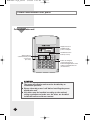
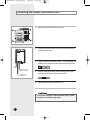
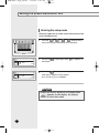
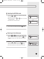
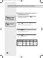
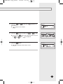
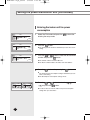
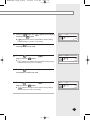
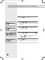
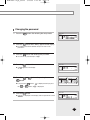
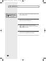
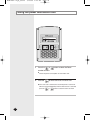
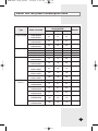
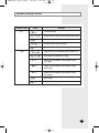
MCM-B102 IM_E_26318
7/25/06 1:43 PM
Page 25
INSTALLATION
MANUAL
Power Distribution Unit
MCM-B102
System Air Conditioner
E DB98-26318A(1)
MCM-B102 IM_E_26318
7/25/06 1:43 PM
Page 2
Safety Precautions
This installation manual explains how to install the power distribution unit.
See the appropriate installation manual for other optional accessories.
WARNING
CAUTION
E-2
◆ Read this installation manual carefully before
installation and check whether the power distribution
unit is installed properly.
◆ Do not attempt to install or repair the power
distribution unit by yourself.
◆ Always consult an authorized service personnel for
repair.
◆ When moving, consult an authorized service
personnel for disconnection and reinstallation of the
power distribution unit.
◆ Ensure that the wall is strong enough to support the
weight of the power distribution unit.
◆ The power distribution unit must be installed with the
rated power supply.
◆ The power distribution unit must be installed
according to the national electrical rules by an
installation specialist.
◆ Consult an authorized installation center on how to
dispose the power distribution unit.
◆ Do not use inflammable gases near the power
distribution unit.
◆ Do not install the power distribution unit in a location
where it will come into contact with combustible
gases, machine oil, sulphide gas, etc.
◆ Avoid a location where acid/alkali solution or special
spray is used.
◆ Install the power distribution unit in a location that is
not exposed to direct sunlight and where the
temperature range is between 0°C and 39°C.
◆ Do not let water into the power distribution unit.
◆ Do not apply pressure to the cable.
The cable may break and cause fire.
◆ Do not press the buttons with a sharp object.
◆ Do not connect the power cable to the control terminal.
◆ Ensure that the power distribution unit does not affect
other electronic devices when installed in a hospital
or other particular places.
MCM-B102 IM_E_26318
7/25/06 1:43 PM
Page 3
Contents
◆ POWER DISTRIBUTION UNIT PARTS . . . . . . . . . . . . . . . 4
◆ SYSTEM DIAGRAM . . . . . . . . . . . . . . . . . . . . . . . . . . . 5
◆ INSTALLING THE POWER DISTRIBUTION UNIT . . . . . . . . 6
◆ SWITCH SETTING OF THE POWER
DISTRIBUTION UNIT PCB
......................7
◆ SETTING THE POWER DISTRIBUTION UNIT
■
ENTERING THE SETUP MODE . . . . . . . . . . . . . . . . . . . . . . . . . . . . 8
SELECTING THE SET/FAN MODE . . . . . . . . . . . . . . . . . . . . . . . . 9
■ RETURNING TO THE INITIAL MODE . . . . . . . . . . . . . . . . . . . . . . . . 9
■ SELECTING THE COMMUNICATION PROTOCOL OF A DIGITAL
ELECTRIC METER . . . . . . . . . . . . . . . . . . . . . . . . . . . . . . . . . . . . 10
■ ENTERING THE INDOOR UNIT FAN POWER CONSUMPTION . . . . . . . 12
■ CHANGING THE PASSWORD . . . . . . . . . . . . . . . . . . . . . . . . . . . . 15
■
◆ TEST OPERATION . . . . . . . . . . . . . . . . . . . . . . . . . . 16
◆ TROUBLESHOOTING FOR COMMUNICATION ERROR . . . 17
◆ USING THE POWER DISTRIBUTION UNIT . . . . . . . . . . 18
◆ INDOOR UNIT FAN POWER CONSUMPTION TABLE . . . . 19
◆ SYSTEM SETUP MODE . . . . . . . . . . . . . . . . . . . . . . . 21
E-3
MCM-B102 IM_E_26318
7/25/06 1:43 PM
Page 4
Power distribution unit parts
Power distribution unit
Mode
Room
KWH
Total
KWH
Displays the total or
individual electric
power consumption
Auto/Manual search
button (For users)
Search button for
consumed electric power
of each room
(For users)
A/M
CLS
2
3
4
5
6
7
9
0
1
8
Ent
Buttons for setting the
communication protocol
between the digital electric meter
and the power distribution unit
(For technicians)
CAUTION
◆ The power distribution unit must be installed by an
installation specialist.
◆ Ensure the main power is off before installing the power
distribution unit.
◆ All cables must be installed according to the national
wiring regulation and make sure the wires are installed
inside the wall to avoid user contact.
E-4
MCM-B102 IM_E_26318
7/25/06 1:43 PM
Page 5
System diagram
➂
Communication cable
①✽
Power supply line
➁
➃
①
Digital electric meter(common)
➁
ELB or NFB :
➂
Power distribution unit :
➃
DVM air conditioners
◆ Interceptor of air conditioners ➞ Main power breaker
◆ MCM-B102
E-5
MCM-B102 IM_E_26318
7/25/06 1:43 PM
Page 6
Installing the power distribution unit
1
Open the power distribution unit cover.
2
Connect the power cable of the power distribution unit
to the power terminal.
3
Connect the communication cable F1, F2 of the indoor and
outdoor unit to the power distribution unit terminal JP201.
Mode SET NET
Room
KWH
Total
KWH
ON
12
A/M
2
3
5
6
7
9
1
0
CLS
4
8
Ent
JP201 JP203 JP202
JP201
JP203
JP202
Power
(220V)
Digital electric meter
communication cable
4
Indoor/Outdoor unit
communication line
Connect the digital electric meter communication cable
to the power distribution unit terminal JP203.
JP201
5
JP203
JP202
Reassemble the power distribution unit.
CAUTION
The communication cable and the power cable
should be installed separately.
E-6
MCM-B102 IM_E_26318
7/25/06 1:43 PM
Page 7
Switch setting of the power distribution unit PCB
Set the DIP switch of the power distribution unit
according to the type of digital electric meter to be
installed. Adjust the switch as shown in the table below.
Switch
status
SW1
SW2
SW3
SW4
Remarks
ON
ON
OFF
OFF
Use RS 485
communication
CAUTION
If the DIP switch of the power distribution
unit PCB is not adjusted properly,
communication error may occur.
SW201
Factory setting of the switch
E-7
MCM-B102 IM_E_26318
7/25/06 1:43 PM
Page 8
Setting the power distribution unit
Entering the setup mode
Enter the setup mode to set the system environment of the
power distribution unit.
A/M
CLS
4
1
2
3
5
6
7
9
0
1
Press the 9 , 0 ,
, Ent buttons on the
key-pad of the power distribution unit in sequence.
2
Press the
the display.
Ent
3
Press the
Ent
8
Ent
Mode
Room
KWH
Total
appears on
KWH
Mode
Room
KWH
Total
button again when
KWH
when
button after entering the password
appears on the display.
◆ The default password is '0000000'.
CAUTION
If there are no key inputs for 3 seconds when
appears on the display, the display
returns to the initial mode.
E-8
MCM-B102 IM_E_26318
7/25/06 1:43 PM
Page 9
Selecting the SET/FAN mode
1
Press the
or
button to select the mode when
Mode SET
Room
the setup screen appears.
KWH
Total
◆ Each time you press the
or
button, you can select
the SET/FAN mode.
◆ The SET mode is selected by default.
KWH
When selecting the SET mode
▼
Mode
FAN
Room
KWH
Total
KWH
When selecting the FAN mode
2
You can enter each mode by pressing the
Ent
button.
Returning to the initial mode
1
Press the
1
or
2
button until
appears on the
display in the SET/FAN mode and press the
Ent
button.
Mode SET
Room
KWH
◆ The mode changes from the SET / FAN mode to the setup
mode.
2
Press the
or
button until
appears on the
Total
KWH
Total
KWH
Mode
Room
display in the setup mode and press the
Ent
button.
◆ The mode changes from the setup mode to the initial mode.
KWH
E-9
MCM-B102 IM_E_26318
7/25/06 1:43 PM
Page 10
Setting the power distribution unit (Continued)
Selecting the communication protocol of
the digital electric meter
1
Select the SET mode and press the
entering the setup mode.
2
KWH
Press the
display.
KWH
◆ The default communication protocol setting is '1'.
Mode SET
Room
KWH
Total
button after
KWH
Mode SET
Room
Total
Ent
3
Press the
2
Ent
button twice when
appears on the
button.
◆ The existing setting of the communication protocol is deleted
and you can enter a new setting.
4
Press the Ent button after entering the desired setting of
the communication protocol.
Button(Setting)
Communication
protocol of a
digital electric
meter
E-10
1
Omni
RS 485
2
3
Korea
LS
Micronics Industrial
RS 485
RS 485
7
Hansuk
Tech
RS 485
MCM-B102 IM_E_26318
5
Press the
the display.
◆
6
1
7/25/06 1:43 PM
or
button until
2
appears on
Mode SET
Room
KWH
Total
appears on the display.
Press the
Ent
button and press the
◆ If you press the
the
7
Page 11
1
or
Ent
2
button,
button,
1
or
2
button.
KWH
Mode SET
Mode SET
Room
Room
KWH
is displayed and if you press
Total
Total
KWH
is displayed.
Press the
Ent
button.
◆
is displayed and the setup is saved.
Mode SET
Room
KWH
Total
KWH
E-11
MCM-B102 IM_E_26318
7/25/06 1:43 PM
Page 12
Setting the power distribution unit (Continued)
Entering the indoor unit fan power
consumption
Mode
FAN
1
Select the FAN mode and press the
entering the setup mode.
2
Press the
Room
KWH
Total
Mode
KWH
FAN
Room
Total
KWH
3
FAN
Room
button.
Press the
1
or
2
number and press the
KWH
Total
Ent
◆ The existing Room number is deleted and you can enter a new
setting.
KWH
Mode
button after
Ent
button to select the desired Room
Ent
button.
◆ The number of Room is 48 from 00 to 47.
◆ The Room number indicates the indoor unit main address.
KWH
4
Press the
Ent
button after pressing the
2
button.
◆ The existing power consumption setting is deleted and you can
enter a new setting.
◆ The default power consumption setting is 'Auto'.
Mode
FAN
Room
Mode
Room
KWH
Total
FAN
5
Press the
1
or
and press the
2
button to select the
Ent
or
button.
KWH Total
◆ You do not have to enter the indoor unit power consumption
setting when you select 'Auto'.
E-12
MCM-B102 IM_E_26318
6
Press the
2
and press the
◆
7/25/06 1:43 PM
button until
Ent
Page 13
appears on the display
KWH
Press the Ent button after entering the indoor unit power
consumption at low fan mode.
8
Press the
2
button and when
display, press the
9
Ent
FAN
Total
indicates the low fan speed and the existing setting
is deleted and you can enter a new setting.
7
◆
Mode
Room
button.
appears on the
Mode
KWH
FAN
Room
button.
KWH
Total
KWH
indicates the medium fan speed and the existing setting
is deleted and you can enter a new setting.
Press the
Ent
button after entering the indoor unit power
consumption at medium fan mode.
10 Press the
2
button and when
display, press the
◆
Ent
appears on the
button.
Mode
FAN
Room
KWH
Total
indicates the high fan speed and the existing setting is
deleted and you can enter a new setting.
KWH
E-13
MCM-B102 IM_E_26318
7/25/06 1:43 PM
Page 14
Setting the power distribution unit (Continued)
11 Press the
Ent button after entering the indoor power
consumption at high fan mode.
Mode
12 Press the
FAN
Room
KWH
Total
Mode
KWH
KWH
Total
Mode
◆
Mode
FAN
FAN
KWH
Total
KWH
Total
button until
2
is displayed.
appears on the display.
14 Press the
or
1
◆ If you press the
the
1
15 Press the
FAN
Room
KWH
E-14
or
2
button after pressing the
Ent
button.
Room
Total
1
KWH
Room
Mode
button until channel is displayed.
2
◆ Adjust the indoor unit power consumption setting for other Rooms
following step 2.
13 Press the
FAN
Room
or
1
KWH
◆
or
Ent
Ent
2
button,
button,
is displayed and if you press
is displayed.
button.
is displayed on the display and the settings are saved.
MCM-B102 IM_E_26318
7/25/06 1:43 PM
Page 15
Changing the password
1
Press the
Ent
button after entering the setup mode.
Mode SET
Room
KWH
Total
2
Press the
Ent
button when
KWH
appears on the display.
◆ The existing password is deleted and you can enter a new
password.
3
Press the
Ent
button after entering new password.
◆ You can set the password up to 7 digits.
4
Press the
◆
2
button 4 times.
Mode SET
Room
appears on the display.
KWH
Total
5
Press the
Ent
1
or
button after pressing the
2
button.
Mode SET
Mode SET
Room
Room
KWH
Total
◆ If you press the
the
6
1
or
Ent
2
button,
button,
Total
KWH
is displayed and if you press
is displayed.
Ent button.
Press the [Ent]
◆
KWH
Mode SET
Room
is displayed on the display and new password is saved.
KWH
Total
KWH
E-15
MCM-B102 IM_E_26318
7/25/06 1:43 PM
Page 16
Test operation
Mode
1
Check if the LCD display turns on after powering on the
power distribution unit.
2
Set the communication protocol between the digital electric
meter and the power distribution unit.
3
Check the communication status by pressing the
Room
KWH
Total
KWH
or
button after completing all the settings for
the communication protocol.
4
E-16
Check if the total value displayed on the power distribution
unit is the same as the digital electric meter's.
MCM-B102 IM_E_26318
7/25/06 1:43 PM
Page 17
Troubleshooting for communication error
1
When there is a communication error between the DVM
air conditioner system and the power distribution unit,
the error message will be displayed as shown in the
picture.
Mode
PDU DVM Error
Room
KWH
Total
KWH
◆ Check if the communication cable is connected properly.
◆ Check if any errors are displayed on the outdoor unit.
2
When there is a communication error between the digital
electric meter and the power distribution unit, the error
message will be displayed as shown in the picture .
Mode
WHM PDU
Error
Room
KWH
Total
KWH
◆ Check if the communication cable is connected properly.
◆ Check if the PCB switch of the power distribution unit is set
correctly.
◆ Check if the communication protocol of the digital electric meter
is set properly.
E-17
MCM-B102 IM_E_26318
7/25/06 1:43 PM
Page 18
Using the power distribution unit
Mode
Room
KWH
Total
1
KWH
A/M
CLS
1
2
3
4
5
6
7
8
9
0
Press the
Ent
or
button to select the Room
number to check.
◆ Check the power consumption of each indoor unit.
A/M
2
Press the
to select auto scan or manual scan.
◆ If the auto scan is selected, the consumed power of each room
will be scanned automatically and if the manual scan is selected,
press the
or
button to select the rooms to check.
E-18
MCM-B102 IM_E_26318
7/25/06 1:43 PM
Page 19
Indoor unit fan power consumption table
Type
1 way cassette
2 way cassette
4 way cassette
Duct
(Built-in)
Indoor unit model
AVMKH020EA4
AVMKC020EA1
AVMKH026EA4
AVMKC026EA1
AVMKH035EA4
AVMKC035EA1
AVXC2H056EA
AVXC2H071EA
AVMGH052EA4
AVMGH070EA4
AVMCH052EA4
AVMCC052EA1
AVMCH070EA4
AVMCC070EA1
AVMCH105EA4
AVMCC105EA1
AVMCH128EA4
AVMCC128EA1
AVMCH140EA4
AVMCC140EA1
AVXDBH071EA
AVMBH020EA4
AVMBC020EA0
AVMBH026EA4
AVMBC026EA0
AVMBH035EA4
AVMBC035EA0
AVMBH052EA4
AVMBC052EA0
AVMBH070EA4
AVMBC070EA0
Indoor unit fan power
consumption(W)
Remarks
L(Low)
M(Medium)
H(High)
35
35
35
35
35
35
40
40
40
33
33
33
33
33
33
33
33
33
33
33
33
56
70
80
56
70
80
88
103
121
104
119
136
140
150
165
140
155
172
74
81
89
74
81
89
74
81
89
140
155
172
140
155
172
E-19
MCM-B102 IM_E_26318
7/25/06 1:43 PM
Page 20
Indoor unit fan power consumption table (Continued)
Type
Duct
(Low-static
pressure)
Duct
(High-static
pressure)
Slim Duct
Ceiling
Wall-mounted
(Prestige)
Wall-mounted
(Premium)
Wall-mounted
(Classic)
E-20
Indoor unit model
AVMDH052EA4
AVMDC052EA0
AVMDH070EA4
AVMDC070EA0
AVMHH105EA4
AVMHC105EA0
AVMHH128EA4
AVMHC128EA0
AVMHH140EA4
AVMHC140EA0
AVMEH020EA3
AVMEH026EA3
AVMEH035EA3
AVMFH052EA4
AVMFH070EA4
AVXWHH028EA
AVXWHH036EA
AVXWPH022EA
AVXWPH028EA
AVXWPH036EA
AVXWPH056EA
AVXWPH071EA
AVMWH020EA4
AVMWC020EA1
AVMWH026EA4
AVMWC026EA1
AVMWH035EA4
AVMWC035EA1
AVMWH052EA4
AVMWC052EA1
AVMWH070EA4
AVMWC070EA1
Indoor unit fan power
consumption(W)
Remarks
L(Low)
M(Medium)
H(High)
150
170
185
150
170
185
458
486
513
458
486
513
458
486
513
68
68
68
58
63
35
35
32
32
35
72
85
68
68
68
67
72
35
35
32
32
35
72
85
68
68
68
75
80
35
35
32
32
35
72
85
42
42
42
42
42
42
42
42
42
85
85
85
85
85
85
MCM-B102 IM_E_26318
7/25/06 1:43 PM
Page 21
System setup mode
Setting mode
SET
Menu
Remarks
Password setup
Digital electric meter communication type setup
Save setup
Restore default factory settings
Exit from the setup mode
FAN
Represents the main address of the indoor unit
Selecting the Auto/Manual mode
Indoor unit FAN power consumption setup
at L mode
Indoor unit FAN power consumption setup
at M mode
Indoor unit FAN power consumption setup
at H mode
Save setup
Exit from the setup mode
E-21
MCM-B102 IM_E_26318
MEMO
E-22
7/25/06 1:43 PM
Page 22
MCM-B102 IM_E_26318
7/25/06 1:43 PM
Page 23
E-23
MCM-B102 IM_E_26318
7/25/06 1:43 PM
Page 24
ELECTRONICS