1
LBI-39055A
MAINTENANCE MANUAL
C3 MAESTRO CONSOLE SYSTEM
INSTALLATION, SET-UP AND TESTING
TABLE OF CONTENTS
Page
GENERAL.......................................................................................................................................................
PERSONAL COMPUTERS ...................................................................................................................
Hardware.............................................................................................................................................
Operating System Software.................................................................................................................
3
4
4
4
BOARD SET-UP .............................................................................................................................................
LOGIC BOARD.......................................................................................................................................
DIP Switches.......................................................................................................................................
SW1 − Dual-Port Address DIP Switch ........................................................................................
SW2 − Interrupt (IRQ) DIP Switch .............................................................................................
Firmware.............................................................................................................................................
Installation Into The PC......................................................................................................................
PLUG-IN RS-422 BOARD (Optional) ...................................................................................................
AUDIO TOWER......................................................................................................................................
Audio PA Board(s) .............................................................................................................................
SW1 − Maximum Speaker Power Level DIP Switch ..................................................................
SW2 − Audio Source DIP Switch................................................................................................
Audio Matrix Board............................................................................................................................
SW1 − Mic Audio ALC Enable/Disable DIP Switch ..................................................................
I/O Board ............................................................................................................................................
4
4
4
4
4
4
5
5
5
5
5
5
6
6
6
INTERCONNECTING THE EQUIPMENT ................................................................................................
CEC/IMC INTERCONNECTIONS.......................................................................................................
Control Data Link ...............................................................................................................................
Remote Console Interconnections Via A 4-Wire Modem ...........................................................
Audio Links ........................................................................................................................................
PERSONAL COMPUTER......................................................................................................................
PC-To-Audio Tower Interconnect Cable ............................................................................................
Dispatch Keyboard .............................................................................................................................
Standard PC Keyboard........................................................................................................................
Video Display Monitor .......................................................................................................................
AUDIO TOWER......................................................................................................................................
Desk Mic (if used) .............................................................................................................................
Headset Jacks (if used) .......................................................................................................................
Boom/Gooseneck Mic (if used) ..........................................................................................................
Boom/Gooseneck PTT and Monitor Switches (if used) .....................................................................
Footswitches (if used) .........................................................................................................................
Volume Controller Box (if used) ........................................................................................................
Speakers (if used)................................................................................................................................
6
7
7
8
9
9
9
12
12
12
12
12
13
13
13
14
14
14
ericssonz
LBI-39055
TABLETABLE
OF CONTENTS
(Continued)
OF CONTENTS
Page
Recorder Outputs (if used) ..................................................................................................................
Pager Input (if used)............................................................................................................................
Relay Outputs (if used) .......................................................................................................................
Call Director (if equipped) ..................................................................................................................
Console-to-CEC/IMC Audio Interconnections ............................................................................
Console-to-Call Director Interconnections ..................................................................................
EQUIPMENT ROOM GROUNDING ...................................................................................................
AC POWER AND UPS EQUIPMENT ..................................................................................................
15
15
15
16
16
16
16
16
POWER-UP PROCEDURE ........................................................................................................................... 18
SOFTWARE INSTALLATION AND SET-UP PROCEDURE ..................................................................
PC CMOS SET-UP PROGRAM ............................................................................................................
Hewlett-Packard Vectra 25N & 486SX/25 .........................................................................................
Data General Dasher 386SX ...............................................................................................................
Data General 386SX/25A (Acer) ........................................................................................................
Compaq 386S......................................................................................................................................
SOFTWARE INSTALLATION AND UPGRADES .............................................................................
FILE DIRECTORIES AND CONTENTS .............................................................................................
AUTOEXEC.BAT File Contents ........................................................................................................
CONFIG.SYS File Contents ...............................................................................................................
EDITOR PROGRAM ..............................................................................................................................
Logic Board Interrupt (IRQ) ...............................................................................................................
COM1 Serial Port Baud Rate..............................................................................................................
Set-Up Titles .......................................................................................................................................
Call Director ID ..................................................................................................................................
Boom/Gooseneck Microphone Presence.............................................................................................
RUNNING THE C3 MAESTRO APPLICATION PROGRAM..........................................................
DATABASE INITIALIZATION ............................................................................................................
Console User Profile Configuration ....................................................................................................
System Manager Database Uploads ....................................................................................................
Console Privilege Lists........................................................................................................................
Saving Database Information ..............................................................................................................
18
18
18
18
18
18
19
19
19
19
19
20
20
20
20
20
20
20
21
21
21
22
SYSTEM TESTS .............................................................................................................................................
LOW-LEVEL TESTS ..............................................................................................................................
Recommended Test Equipment...........................................................................................................
Set-Up Procedure ................................................................................................................................
Test Procedure ....................................................................................................................................
1. Send LINE A Input Audio to SPEAKER A.............................................................................
2. Send LINE B Input Audio to SPEAKER B .............................................................................
3. Send Mic Audio To LINE A & LINE B Outputs.....................................................................
4. Test Audio PA Board #2 (if installed) .....................................................................................
5. Completion...............................................................................................................................
HIGH-LEVEL TESTS.............................................................................................................................
Control Data Link ...............................................................................................................................
Audio Links.........................................................................................................................................
22
22
22
22
22
22
23
23
24
24
24
24
24
CABLE ASSEMBLY DIAGRAMS
CONTROL DATA CABLE (100-FOOT) 19B804083P3 ...................................................................... 25
AUDIO CABLE (100-FOOT) 19B804083P5 ......................................................................................... 26
Copyright June 1994, Ericsson GE Mobile Communications, Inc.
2
LBI-39055
3.06
(344A3564G10,
344A3565G10,
344A3567G10 and 344A3568G10)
GENERAL
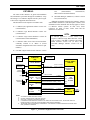
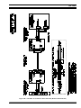
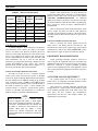
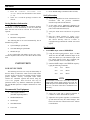
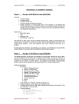
The intent of this manual is to guide field installation
and maintenance personnel through the installation, set-up
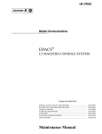
and testing of a C3 Maestro dispatch console system. Figure
1 shows basic equipment interconnections.
This document was developed in accordance with:
•
•
•
•
•
C3 Maestro (PC) application software version 3.0x
(344A3922G10)
•
CEC/IMC Manager (MOM PC) software version
3.05 (344A3630G10)
Although specifically written for the firmware, software
and hardware listed above (and subsequent versions), most
information in this document also directly applies to earlier
C3 Maestro console systems. In most cases, direct
references are made to these earlier items and the
differences are described.
C3 Maestro Logic Board firmware version 3.02
(344A4245G10)
NOTE
NOTE
C3 Maestro application software version 3.0x
requires C3 Maestro Logic Board firmware version
3.02 (or later), CEC/IMC Controller and Audio
Board firmware version 3.0x (or later), and
CEC/IMC Manager software version 3.0x (or
later).
C3 Maestro Logic Board hardware revision B
(344A3927P24 or P29/5000060001)
C3 Maestro Audio Tower later-revision hardware
commonly referred to as "Phase 2" (board
assemblies designated with a P29/772xxxxxxx part
numbers)
CEC/IMC Digital Audio Switch firmware version
VIDEO
DISPLAY
MONITOR
PERSONAL
COMPUTER
(PC)
DISPATCH
KEYBOARD
CEC/IMC
DIGITAL AUDIO
SWITCH
LOGIC BOARD
STANDARD PC
KEYBOARD
SELECT
SPEAKER
CONTROL DATA
COM1
(RS-232 = 3 WIRES)
(RS-422 = 4 WIRES)
AUDIO TOWER
CIM
CONTROLLER
BOARD
AUDIO MATRIX BD.
MIC
UNSELECT
SPEAKER
#1
LINE A OUT
AUDIO
PA BD.
#2
LINE B OUT
I/O
BOARD
NOTES:
1.
2.
3.
4.
5.
SELECT AUDIO
(2 WIRES)
MIC AUDIO
(2 WIRES)
TX1
RX1
UNSELECT AUDIO
(2 WIRES)
TX2
CD PATCHED RADIO AUDIO (2 WIRES)
TX4
CD/DISP. CON. MIC AUDIO
RX4
LINE A IN
AUDIO
PA BD.
#1
LINE B IN
LINE B IN
{
CD
(2 WIRES)
CD RECEIVER AUDIO
(2 WIRES)
CD MIC AUDIO
CD CONTROL
(2 WIRES)
(5 WIRES)
CIM
AUDIO
BOARD
CALL
DIRECTOR
PHONE
LINES
AC POW ER CONNECTIONS NOT SHOWN.
CEC/IMC CONCENTRATOR CARDS NOT SHOW N.
ONLY ONE (1) UNSELECT SPEAKER IS SHOWN.
IF CONSOLE SYSTEM DOES NOT SUPPORT CALL DIRECTOR TELEPHONE PATCH, THE SECOND AUDIO PA
BOARD (#2) AND ALL RELATED CD INTERCONNECTIONS ARE NOT REQUIRED.
THE SECOND AUDIO PA BOARD (#2) IS REQUIRED IF THE CONSOLE SYSTEM IS EQUIPPED WITH MORE THAN
ONE (1) UNSELECT SPEAKER.
Figure 1 − C3 Maestro Equipment Interconnections
3
LBI-39055
PERSONAL COMPUTERS
BOARD SET-UP
In most cases, the Personal Computer (PC) used with
the C3 Maestro console is delivered with the Logic Board
installed, its hard disk drive formatted and MS-DOS
operating system software installed on the hard disk drive.
The C3 Maestro application software is also installed on the
drive.
Hardware
LOGIC BOARD
Normally, the Logic Board is configured correctly and
installed inside the PC before the C3 Maestro console
system is delivered to the customer. The following
information is presented for reference only.
DIP Switches
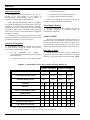
Table 1 lists the PCs approved for use with a C3
Maestro console system. Use of an unapproved computer
will void the console system's warranty and support services.
Subsequent to the printing of this manual, additional PCs not
listed in the table may be approved.
TABLE 1 − APPROVED PERSONAL COMPUTERS
FOR USE WITH THE C3 MAESTRO
MANUFACTURER
MODEL NO. OR TYPE
Hewlett-Packard
Vectra 25N
Hewlett-Packard
486SX/25
Data General
Dasher 386SX/16
Data General
Dasher 386SX/20
Data General*
386/25A
Compaq
386S
* Manufactured for Data General by Acer; all plastic case.
Operating System Software
The PC will have either MS-DOS version 3.3, 5.x or 6.x
installed on its hard drive. MS-DOS 5.x or 6.x is preferred.
All Data General and Hewlett-Packard computers ship from
the factory with either MS-DOS 5.x or 6.x. MS-DOS 4.x is
not approved for use with the C3 Maestro console system.
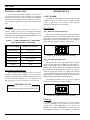
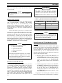
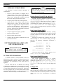
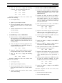
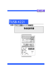
SW1 − Dual-Port Address DIP Switch
All positions of DIP switch SW1 on the Logic Board
should be in the "ON" or "CLOSED" position. This sets the
base address of the dual-port RAM chip on the board to
D000:0000 (hex). SW1 switch should never be configured
in any other way. Figure 2 shows the "0000" setting.
ON
1
2
3
4
Figure 2 − Logic Board SW1 Factory Setting
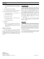
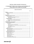
SW2 − Interrupt (IRQ) DIP Switch
DIP switch SW2 on the Logic Board sets the board's
interrupt request (IRQ) line. It should be set with position 1
"ON" or "CLOSED" and all other positions "OFF" or
"OPEN". This sets the interrupt to seven (IRQ7). Normally,
SW2 should not be configured in any other way. Figure 3
shows the setting. This setting is not a binary-code decimal
equivalent representation of the interrupt number; the switch
simply provides a single-pole four-throw switch function
using four single-pole single-throw DIP switches.
Logic Boards previous to Rev. A were not equipped
with SW2; the interrupt was hardwired as IRQ7.
NOTE
IMPORTANT
NOTE
ON
Unless otherwise noted, all procedures in this
manual should be performed in the order presented.
1
2
3
4
Figure 3 − Logic Board SW2 Factory Setting
Firmware
EPROM integrated circuit U4 on the Logic Board
stores the operating program firmware for the on-board
microprocessor. After programming at the factory, the
EPROM (part number 344A4245Gx) is labeled with the
corresponding firmware version number. C3 Maestro
4
LBI-39055
application software version 3.0x requires Logic Board
firmware version 3.02 (part number 344A4245G10) or later.
If necessary, verify the proper EPROM is installed into U4's
socket.
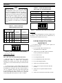
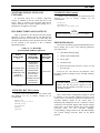
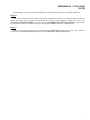
is recommended, as it should be adequate in nearly all
dispatch environments. Table 2 indicates the available
settings and Figure 4 shows the 5-watt factory setting. These
switches have no effect on headset earphone output levels.
Installation Into The PC
The Logic Board is installed in an expansion slot inside
the PC. Although it can be installed in any slot, installing it
in the slot furthest from the PC's internal power supply is
recommended. If field installation is necessary, follow this
procedure:
1.
Review the procedures in the documentation
included with the PC related to expansion board
installation.
2.
If necessary, power-down the PC and disconnect
it from the ac power source.
3.
Remove the outside cover from the PC in
accordance with the manufacturer's instructions.
4.
Select an empty expansion slot and remove the
respective rear cover plate. Retain the hold-down
screw. Discard the rear cover plate.
5.
Install the Logic Board in the selected expansion
slot. Secure it with the hold-down screw.
6.
Replace the outside cover.
NOTE
NOTE
SW1 is not present on Audio PA Board
P29/5000055000. Both speaker power amplifiers
on this earlier board (sometimes referred to as a
"Phase 1" board) are hardwired for 8 watts
maximum output. See LBI-38716 for details.
TABLE 2 − AUDIO PA BOARD
MAX. SPEAKER POWER LEVEL SELECTION
SW1
POSITION
MAXIMUM
OUTPUT
1
2
3
4
SPKR A
SPKR B
OFF
OFF
x
x
5 Watts
5 Watts
ON
OFF
x
x
8 Watts
5 Watts
OFF
ON
x
x
5 Watts
8 Watts
ON
ON
x
x
8 Watts
8 Watts
"x" = either position
PLUG-IN RS-422 BOARD (Optional)
If the PC is equipped with a plug-in RS-422 capable
board, see the section entitled "INTERCONNECTING
subsection
"CEC/IMC
THE
EQUIPMENT",
INTERCONNECTIONS" for set-up information.
AUDIO TOWER
All necessary slide-in boards are installed in the Audio
Tower before the C3 Maestro console system ships from the
factory. If the console system is ordered with multiple
unselect speakers (2 or 3) or with the Call Director patch
option, two Audio PA Boards are installed. DIP switches
and jumpers/plugs located on the Audio Matrix and Audio
PA Boards are factory configured for standard console
installations. The following information lists the normal
factory settings and the optional settings which are available.
Audio PA Board(s)
SW1 − Maximum Speaker Power Level DIP Switch
ON
1
2
3
4
Figure 4 − Audio PA Board SW1 Factory Setting
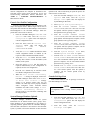
SW2 − Audio Source DIP Switch
During normal console operations, SW2 positions 1 and
3 should always be "ON" or "CLOSED" and SW2 positions
2 and 4 should always be "OFF" or "OPEN". Figure 5
shows this setting.
For test procedures, SW2 positions 1 thru 4 may be
inverted to shift the Speaker A and Speaker B audio
amplifiers' source audio from the Audio Matrix Board
(normal) to Line A and Line B balanced inputs (test),
respectively. See LBI-39064 for specific details. With this
test setting, audio signals on the line inputs are applied
directly to the speakers' power amplifiers without being
routed through the Audio Matrix Board.
Switch SW1 on the Audio PA Board provides a method
to limit the maximum audio output from each speaker power
amplifier. Maximum levels of 5 watts or 8 watts are
available. Normally, the factory setting is 5-watts. This level
5
LBI-39055
TABLE 4 − AUDIO MATRIX BOARD
MIC AUDIO ALC ENABLE/DISABLE
NOTE
NOTE
SW2 is not present on Audio PA Board
P29/5000055000. Audio source selection on this
earlier board (sometimes referred to as a "Phase 1"
board) is accomplished via two jumpers/plugs
identified as JP1 and JP2. During normal (non-test)
console operations, jumpers must be in between
pins "A" and "C" on both plugs. These settings
route Line A and Line B audio signals from the
Audio PA Board to the Speaker A and Speaker B
power amplifiers. See LBI-38716 for additional
details.
SW1 POSITION
MIC
1
Boom/Gooseneck
2
Desk
3
Operator Headset
4
Supervisor Headset
ON
TABLE 3 − AUDIO PA BOARD
AUDIO SOURCE SELECTION
SOURCE
OUTPUT
x
Matrix Bd.
Speaker A
x
Line A In
Speaker A
3
4
ON OFF
x
OFF ON
x
x
x
2
2
3
4
Figure 6 − Audio Matrix Board SW1 Factory Setting
SW2 POSITION
1
1
x
ON OFF
Matrix Bd.
Speaker B
x
OFF ON
Line B In
Speaker B
I/O Board
No I/O Board configuration is necessary. Simply verify
the Board is fully inserted into the far left-hand slot (as
viewed from back of Audio Tower's case).
INTERCONNECTING THE
EQUIPMENT
"x" = either position
A C3 Maestro dispatch console system requires the
following interconnections:
ON
1
2
3
4
Figure 5 − Audio PA Board SW2 Factory Setting
•
•
PC-to-CEC/IMC Data Concentrator Card
(via punch blocks, if employed)
Audio Tower-to-CEC/IMC Audio Concentrator
Card (via punch blocks, if employed)
Audio Matrix Board
•
PC-to-Audio Tower
SW1 − Mic Audio ALC Enable/Disable DIP Switch
•
PC-to-Dispatch Keyboard
DIP switch SW1 on the Audio Matrix Board is used to
independently enable or disable each microphone's
automatic level control (ALC) circuit. The switch has four
(4) positions, one for each mic that may be connected to the
board.
•
PC-to-Standard Keyboard (when in use)
•
PC-to-Video Display Monitor
•
Audio Tower-to-Desk Mic (if used)
As shown in Figure 6, Audio Matrix Boards ship from
the factory with all mic audio ALC circuits enabled. This is
accomplished by setting all four SW1 switch positions to
"ON" or "CLOSED". Table 4 lists each switch position and
its corresponding mic input. Normally, mic audio ALC
should not be disabled. Disable a mic's ALC by setting the
corresponding DIP switch position to "OFF" or "OPEN".
•
6
•
•
Audio Tower-to-Supervisor Headset Jack Box
(if used)
Audio Tower-to-Operator Headset Jack Box
(if used)
Audio Tower-to-Boom/Gooseneck Mic (if used)
LBI-39055
•
Audio Tower-to-Boom/Gooseneck PTT and
Monitor Switches (if used)
•
Audio Tower-to-Footswitches (if used)
•
Audio Tower-to-Volume Controller Box (if used)
•
Audio Tower-to-Speakers (if used)
•
PC, Video Display Monitor and Audio Tower AC
Power Connections
In addition, the following interconnections are required
for optional equipment, if employed:
•
Audio Tower-to-Recorder Equipment
•
Audio Tower-to-Pager
•
•
Audio Tower-to-External Equipment Controlled by
Relay Form-A Contacts
Audio Tower-to-Call Director
NOTE
IMPORTANT NOTE
Unless otherwise noted, all procedures in this
manual should be performed in the order presented.
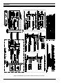
CEC/IMC INTERCONNECTIONS
The C3 Maestro console interfaces to the CEC/IMC via
a full-duplex serial control data link and a 4-wire audio
connection. In addition, each unselect speaker requires an
additional 2-wire connection from the CEC/IMC. Also, if
the console is interfaced to a Call Director for Call Director
telephone patch operations, an additional 4-wire audio link
between the C3 Maestro and the CEC/IMC is required. See
Figures 1 and 8. As shown in Figure 8, all CEC/IMC
interconnections are made at Concentrator Cards. These
cards are located at the back of the CEC/IMC cabinet.
CEC/IMC Concentrator Card pin-out details are listed
on the customer-specific system documentation print-outs.
These print-outs are included with the CEC/IMC when it
ships from the factory. See the CEC/IMC Digital Audio
Switch
Customer-Specific
System
Documentation
maintenance manual, LBI-38939 for sample print-outs and
complete print-out explanations.
RS-422 and therefore, it should never be used for cable runs
more than 50 feet in length.
If required for a remote console installation, full-duplex
4-wire data modems can be used between the C3 Maestro
and the CEC/IMC. See the following subsection for
additional remote console wiring and modem configuration
details.
At the C3 Maestro, control data connections terminate
at the PC's COM1 serial port. On the CEC/IMC side, the
console's control data connections are made at a Data
Concentrator Card. As shown in Figure 8A, punch blocks
may be installed between the CEC/IMC and the console.
Also shown in the figure, a Concentrator Card Cable
interconnects the Data Concentrator Card to the CIM
Controller Board via the CEC/IMC Backplane.
All Data General (DG) Dasher computers are factory
equipped with a built-in COM1 serial port on the main
board that can be wired for RS-422 or RS-232 operation.
The connector is a DB-25 type. See Figure 8A.
Computers not equipped with a main board RS-422
capable COM1 port normally have a plug-in RS-422 board
installed in an expansion slot. This board has a DB-25
connector at its rear plate. Approved RS-422 plug-in board
model numbers include RS422AT-P,
RS422I-P and
3PXOCC1A. An RS422x-x board (part number
344A3927P38) can easily be identified by the presence of
two LED indicators visible on its rear plate. If a plug-in RS422 board is used, the PC's main board COM1 port must be
disabled. This is done via a DIP switch, jumper, or a BIOS
set-up program. For COM1 port enable/disable
configuration details, refer to the section entitled
"SOFTWARE
INSTALLATION
AND
SET-UP
PROCEDURE", subsection "PC CMOS SET-UP
PROGRAM" later in this manual, and the PC
manufacturer's documentation.
Factory-installed RS422x-x (344A3927P38) or
3PXOCC1A plug-in boards are configured correctly before
the PC ships from the factory. This configuration includes
disabling the PC's main board COM1 port per
manufacturer's instructions.
RS422x-x board configuration is:
Address Switches A3-A9
All On (RS422AT-P)
Address Switches A3-A9
All Off (RS422I-P)
Interrupt Jumper
Control Data Link
Either an RS-422 (four-wire) or an RS-232 (three-wire)
serial control data link may be employed. RS-422 control
data interfacing is recommended and in most all
installations, it is used for co-located console
interconnections. RS-232 has poorer noise performance than
IN4
LD GND Jumper
In
LD Jumper
In
DX Jumper
In
SX Jumper
Out
HDX Jumper
Out
7
LBI-39055
FDX Jumper
SLOT 8 Jumper
-BIAS and +BIAS
In
•
Out (RS422AT-P)
DCE Rate = 9600
Out (RS422I-P)
Originate/Answer = Originate (CEC/IMC modem)
Originate/Answer = Answer (C3 Maestro modem)
Configuration for the 3PXOCC1A board is:
Address Switches (S1)
Interrupt Jumper
Modem Options
V.32 Fast Train = Enabled
All Off
Auto Retrain = Enabled
IRQ4
Jumpers JP12 − JP15
Upper Position
Internal/External Clock = Internal
Jumpers JP16 − JP17
Lower Position
Dial-Up/Leased Line = Leased
2-Wire/4-Wire = 4 Wire
If any other RS-422 plug-in serial board is used the
following board configuration must be used:
COM Port
Port Address
Interrupt
TX Level = (as required; use -15 dBm if line loss is 0 dB)
COM1
Dial Backup = Manual
3F8
Loop Back Time = 15 minutes
IRQ4
Dial Line = RJ11
See Figure 8A or the manufacturer's documentation for
COM port connector pin-out details. As required,
interconnect the control data connections between the PC
and the appropriate CEC/IMC Data Concentrator Card or
the respective punch block. Shielded pairs are
recommended.
Line Current Disconnect = Long
Long Space Disconnect = Enabled
V.22 Guard Tone = Disabled
•
MNP Protocol = Enabled
In some cases, the console equipment package is
equipped with a factory pre-wired 100-foot control data
cable. This cable has a female DB-25 connector on one end
for mating to the RS-422 plug-in serial board's male DB-25
connector. The other end is "pig-tailed" (unterminated) so
the wires may be punched down to the appropriate terminals
on the CEC's/IMC's punch block. If utilizing the pre-wired
cable, see the Cable Assembly Diagram near the end of this
manual for wire color coding.
Remote Console Interconnections Via A 4-Wire Modem
When the C3 Maestro is installed at a remote location
from the CEC/IMC, serial control data must be routed via
RS-232 connections and 4-wire modems. Since the C3
Maestro requires a dedicated or continuous serial link (nondial-up), a 4-wire leased line (or equivalent) meeting 3002
data grade specifications must be employed between the
CEC/IMC and the C3 Maestro in a remote console
installation.
Figure 8B shows typical control data interconnections
for a remote console installation using RS-232 connections
and full-duplex 4-wire modems. At the CEC/IMC Data
Concentrator Card, RS-232 connections are made at J13, not
J12. Observe all notes listed in the figure if wiring an
installation of this type. Recommended modem settings are:
MNP Options
Auto Fallback = Enabled (or Normal)
Flow Control = CTS Only
XON/XOFF Pass Through = Enabled
Data Compression = Disabled
Inactivity Timer = Off
Break Control = 5
•
DTE Options
Synchronous/Asynchronous Data = Asynchronous
DTE Rate = 9600
Character Length = 8 Bits
Parity = None
Commanded Dialer = Asynchronous
AT Command Set = Disabled
DTR Control = Disabled
DSR = Forced High
DCD = Normal
CTS = Forced High
DTE Fallback = Disabled
Options = Retained At Disconnect
8
LBI-39055
•
•
•
Test Options - All Disabled (or factory defaults)
Dial Line Options - (not applicable; leave at factory
defaults)
Speaker Options
mating to one of the Audio Board's modular jacks. The other
end is "pig-tailed" (unterminated) so it may be punched
down to the appropriate terminals on the CEC's/IMC's punch
block. If utilizing the pre-wired cables, see the Cable
Assembly Diagram at the end of this manual for wire color
coding.
Volume Control = Low
PERSONAL COMPUTER
Control = On Until Carrier Detect
Audio Links
PC-To-Audio Tower Interconnect Cable
Audio Concentrator Cards at the back of the CEC/IMC
cabinet provide audio connections at the CEC/IMC. See the
customer-specific system documentation print-outs for
Concentrator Card connector pin-out details. Normally,
these connections are extended out of the CEC/IMC cabinet
via Telco cables and connections are actually made at punch
blocks.
The PC-to-Audio Tower Interconnect Cable (part
number P29/1030050000) must be connected between the
PC and the Audio Tower. This cable has male DB-37
connectors on both ends with the connectors' pins wired in a
straight-through pin-to-pin fashion - pin 1 to pin 1, pin 2 to
pin 2, etc. The cable is ten (10) feet long and it should not
be lengthened.
At the C3 Maestro, audio connections terminate at
RJ-11 modular jacks on the Audio PA Board(s) in the Audio
Tower. These jacks are labeled "LINE A" and "LINE B".
Table 6 shows line requirements between the C3 Maestro
and the CEC/IMC for each audio input or output 2-wire pair.
Note that two (2) output pairs, Line B out on board #1 and
Line A out on board #2, are never used. Table 5 gives the
modular jack pin-outs and Figure 7 shows their locations.
Interconnect the required pairs between the Audio PA
Board(s) and the appropriate CEC/IMC Audio Concentrator
Card or punch block. Shielded pairs are recommended.
Mate one male DB-37 connector to the Logic Board
and mate the other to the Audio Matrix Board's connector
labeled "COMPUTER".
NOTE
NOTE
Do not over-tighten the screws on the DB-style
connectors.
In some cases, the console equipment package is
equipped with factory pre-wired 100-foot modular cables for
audio interconnections between the console and the
CEC/IMC. Each has a RJ-11 modular plug on one end for
TABLE 5 − CONSOLE-TO-CEC/IMC BALANCED
LINE AUDIO INTERCONNECTIONS
STANDARD
6-POSITION
4-CONTACT
RJ-11 PIN
NUMBER
*
AUDIO PA
BOARD
6-POSITION
4-CONTACT
RJ-11 PIN
NUMBER
1
(none)
(n/a)
2
1
CIM Line Out
3
2
CIM Line In
4
3
CIM Line In
5
4
CIM Line Out
6
(none)
(n/a)
* RJ-11 pins 1 and 6 are not used.
PA #1
PA #2
RELAY 1
RELAY 1
RELAY 2
RELAY 2
LINE A
TO/FROM
CEC/IMC
LINE A
SELECT AUDIO
AND MIC
LINE B
UNSELECT #1
(LINE OUT PAIR
NOT USED)
LINE B
DIG. IN 1
DIG. IN 1
DIG. IN 2
DIG. IN 2
UNSELECT #2
(LINE C), (LINE
OUT PAIR NOT
USED)
CD PATCH AUDIO
(LINE D)
OR
UNSELECT #3
Figure 7 − Audio PA Boards' Modular Jacks
9
LBI-39055
Figure 8A − CEC/IMC-To-C3 Maestro Interconnections (Co-Located)
10
LBI-39055
Figure 8B − CEC/IMC-To-C3 Maestro Interconnections (Remote And/Or RS-232)
11
LBI-39055
(see LBI-39056 for details)
Dispatch Keyboard
The Dispatch Keyboard interfaces to the PC via
circuitry on the Logic Board. Its part number is
P29/7590182002 (344A3927P25). This keyboard is
sometimes referred to as the "custom keyboard".
AUDIO TOWER
All Audio Tower-related cables should be routed out of
the bottom of the case through the cut-out in the bottom of
the rear door. If necessary, some or all of the cables can be
routed under the case's stand and out to the front of the
Audio Tower. Secure the cables with cable ties as necessary.
During dispatch operations, the standard PC keyboard is
not used. However, during the console set-up process,
access to this keyboard will be required:
to configure certain items via the Editor program
to start the console's application program
Interconnect the video display monitor's video cable to
the Personal Computer in accordance with the
manufacturer's instructions.
Standard PC Keyboard
•
•
Video Display Monitor
If disconnection is necessary, pull on the sleeve and not
on the cable. Pulling on the cable will not free the latch and
may damage the cable if excessive force is used.
for
file
management
(for
example
AUTOEXEC.BAT and CONFIG.SYS file changes
may be necessary)
to start and operate the CTEST test program
Connect the standard PC keyboard to the PC in
accordance with the manufacturer's instructions.
Connect the Dispatch Keyboard to the PC by plugging
its 4-pin interlocking plug to the round socket at the Logic
Board's rear cover plate. If the Logic Board is vertically
orientated, this socket is located just above the female DB37 connector. When correctly mated, the red dot on the plug
will be in a 3 o'clock or 9 o'clock position if the Logic Board
is vertically orientated.
•
•
Desk Mic (if used)
Connect the desk microphone (option CRMC3D or
equivalent) to the Audio Tower by mating its male DB-9
connector to the female DB-9 connector labeled "DESK
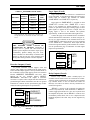
TABLE 6 − C3 MAESTRO-TO-CEC/IMC AUDIO LINE REQUIREMENTS
AUDIO PA BOARD #1
AUDIO MATRIX BOARD LABELING
LINE A
LINE B
LINE A
LINE B
C3 MAESTRO DESIGNATION
LINE A
LINE B
LINE C
LINE D
CEC/IMC DESIGNATION
LINE 1
LINE 2
LINE 3
LINE 4
CONSOLE
IN
OUT
IN
OUT
IN
OUT
IN
OUT
CEC/IMC
OUT
IN
OUT
IN
OUT
IN
OUT
IN
SELECT SPEAKER/HEADSET
X
MICROPHONE
UNSELECT SPEAKER #1
X
XX
UNSELECT SPEAKER #2
XX
UNSELECT SPEAKER #3 *
XX
CALL DIRECTOR PATCH
XX
"X" = 2-wire connection always required
"XX" = 2-wire connection required if console is so equipped
*
= Unselect speaker #3 not available if console is equipped with Call Director patch
12
AUDIO PA BOARD #2
XX
LBI-39055
CAUTION
MIC" on the Audio Matrix Board. The desk mic's cable is
five (5) feet long.
NOTE
NOTE
Do not over-tighten the screws on the DB-style
connectors.
Headset Jacks (if used)
CAUTION
DO NOT connect a boom or gooseneck
microphone to one of the other DB-9 microphone
connectors on the Audio Matrix Board. Damage to
the boom/gooseneck mic's magnetic voice coil may
occur.
TABLE 7 − BOOM/GOOSENECK MIC WIRING*
At the selected location, secure each headset jack box
(part of option CRCN1W or equivalent) to the mounting
surface using the four (4) #10 thread-forming screws
supplied in the installation kit. Before mounting, verify
adequate clearance is maintained for the headset's plugs. If
using both jack boxes, label them "SUPERVISOR" and
"OPERATOR".
WIRE COLOR
DB-9 PIN NUMBER
Black
9
White
5
Shield
1
* Also see the following NOTE.
Connect the headset jack boxes to the Audio Tower
using the 6-foot cable supplied. This cable (part number
19C337102P1 supplied with CRCN1W) has male DB-9
connectors on both ends. One end mates with the female
DB-9 connector at a headset jack box and the other end
mates to the female DB-9 connector at the Audio Matrix
Board. Headset connectors at the Audio Matrix Board are
labeled "SUPERVISOR HEADSET" and "OPERATOR
HEADSET". Interconnect the cables accordingly.
NOTE
NOTE
Microphone priority is (highest to lowest):
•
Supervisory Headset Mic
•
Operator Headset Mic
•
Boom/Gooseneck Mic
•
Desk Mic
The boom/gooseneck mic has priority over the desk
mic when no headset is plugged into the Audio
Tower. Desk mic PTTs will be ignored if a headset
is connected to the Audio Tower.
NOTE
NOTE
All boom and gooseneck mic connectors (male DB9) must have pins 2 and 3 jumpered together so the
sense circuit will be active when the mic is
connected to the Audio Matrix Board.
Boom/Gooseneck PTT and Monitor Switches
(if used)
Boom/Gooseneck PTT and monitor switch input
connections are located at the terminal block labeled "B/G
PTT" and "MON PTT" on the I/O Board. Each input is
wired in parallel at the following points and thus may be
activated from any one of several locations. See the
schematic in the appropriate board's maintenance manual for
specific connector pin-out details:
•
B/G PTT input is located at the "B/G PTT" &
"MON PTT" terminal block on the I/O Board, at
the "FOOTSWITCH 2" female DB-9 connector
on the I/O Board, and at the "BOOM/GOOSE
MIC" female DB-9 connector on the Audio Matrix
Board.
•
Monitor switch input is located at the "B/G PTT"
& "MON PTT" terminal block on the I/O Board, at
the "FOOTSWITCH 1" female DB-9 connector
on the I/O Board, at the "FOOTSWITCH 2"
female DB-9 connector on the I/O Board, and at
the "DESK MIC" female DB-9 connector on the
Audio Matrix Board.
Boom/Gooseneck Mic (if used)
A boom microphone (option CRMC3E or equivalent)
or a gooseneck microphone (option CRMC3F or equivalent)
may be connected to the Audio Tower. Mount the
microphone in accordance with the instructions supplied.
With the gooseneck microphone, the supplied male DB-9
connector must be soldered to the cable in accordance with
Table 7. Connect the boom/gooseneck male DB-9 connector
to the female DB-9 connector labeled "BOOM/GOOSE
MIC" on the Audio Matrix Board. Cable length is four (4)
feet.
Using Figure 9 as a terminal guide, connect the switches
to the screw terminals. Each switch should be a momentary-
13
LBI-39055
contact normally-open type. The ground connections are
common.
B/G PTT
INPUT
(TOP)
B/G PTT
GROUND
MONITOR PTT
INPUT
MONITOR PTT
GROUND
B/G PTT
MON PTT
Figure 9 − I/O Board Boom/Gooseneck PTT and
Monitor Terminal Block Pin-Out
Footswitches (if used)
Two (2) female DB-9 connectors are located on the I/O
Board for footswitch interconnections. "FOOTSWITCH 1"
keys the desk mic and "FOOTSWITCH 2" keys the headset
and boom/gooseneck mics. Footswitches used with the C3
Maestro dispatch console include single-footswitch option
CRSU3B and dual-footswitch option CRSU3C. On the dualfootswitch, one switch keys the mic and the other switch is a
monitor switch. Each input is wired in parallel at the
following points and thus may be activated from any one of
several locations. See the schematic in the appropriate
board's maintenance manual for specific connector pin-out
details.
•
B/G PTT input is located at the "B/G PTT" &
"MON PTT" terminal block on the I/O Board, at
the "FOOTSWITCH 2" female DB-9 connector
on the I/O Board, and at the "BOOM/GOOSE
MIC" female DB-9 connector on the Audio Matrix
Board.
•
Monitor switch input is located at the "B/G PTT"
& "MON PTT" terminal block on the I/O Board, at
the "FOOTSWITCH 1" female DB-9 connector
on the I/O Board, at the "FOOTSWITCH 2"
female DB-9 connector on the I/O Board, and at
the "DESK MIC" female DB-9 connector on the
Audio Matrix Board.
•
Desk mic PTT is located at the "FOOTSWITCH
1" female DB-9 connector on the I/O Board and at
the "DESK MIC" female DB-9 connector on the
Audio Matrix Board.
All footswitch cables terminate with male DB-9
connectors. Mate the appropriate male DB-9 footswitch
connector to the respective female DB-9 connector on the
I/O Board.
14
Volume Controller Box (if used)
If the console system is equipped with speakers, the
Volume Controller Box must be used. Typically, it is
located under the video display monitor but it may be placed
at any convenient location within cable reach of the Audio
Tower. The supplied cable is ten (10) feet in length.
The cable used with the Volume Controller Box has
male DB-15 connectors on both ends. Its part number is
P29/1030049000. Mate one end of this cable to the DB-15
connector at the back of the Volume Controller Box. Mate
the other end to the female DB-15 connector labeled
"VOLUME CONTROLLER" at the bottom of the Audio
Tower's rear panel. This connector is located on the
Spreader Board.
Each Audio PA Board installed in the Audio Tower that
has speakers connected to it must have a "jumper" cable
connected between its "VOLUME CONTROLLER" DB-9
connector and the Spreader Board. The "jumper" cable's
part number is P29/1030048000. If the second Audio PA
Board (#2) is used only for Call Director interfacing, it will
not have any speaker connections and it will therefore not
require a "jumper" cable.
Only one "jumper" cable is required for a 2-speaker
console. A 3- or 4-speaker console which is equipped with
two Audio PA Boards requires two "jumper" cables.
Connect a "jumper" cable between the first Audio PA
Board's connector labeled "VOLUME CONTROLLER"
and the connector labeled "A" on the Spreader Board. The
first Audio PA Board (#1) is located in the slot adjacent to
the Audio Matrix Board. If the console system has 3- or 4speakers, connect a second "jumper" cable between the
second Audio PA Board's connector labeled "VOLUME
CONTROLLER" and the connector labeled "B" on the
Spreader Board. The second Audio PA Board (#2) is
located in the Audio Tower's far right-hand slot as viewed
from the back of the Audio Tower.
Speakers (if used)
Mount the speakers in a suitable location. Connect the
leads from each speaker to the terminal block's screw
terminals on the Audio PA Board as specified in Table 8.
These terminals are not polarity sensitive. Load resistors are
not required for unused speaker outputs.
LBI-39055
TABLE 8 − SPEAKER CONNECTIONS
SPEAKER
AUDIO PA
BOARD
TERMINAL
BLOCK
LABELING
SCREW
TERMINALS
Select
#1 *
SPKR A
upper two
Unselect #1
#1 *
SPKR B
lower two
Unselect #2
#2 *
SPKR A
upper two
Unselect #3
#2 *
SPKR B
lower two
* Audio PA Board #1 is the board in the slot adjacent to the
Audio Matrix Board. Audio PA Board #2 is the board in the
far right-hand slot as viewed from the back of the Audio
Tower.
CAUTION
CAUTION
THE SPEAKER LEADS CANNOT BE
CONNECTED TO GROUND. Connecting a
speaker lead to ground will short-circuit the
speaker power amplifier and reduce output power
considerably. Speaker damage may also occur.
These terminals are intentionally not labeled with
polarity to help prevent any of the terminals from
being connected to ground or to another amplifier.
Recorder Outputs (if used)
To provide call-check recorder support, select and
unselect audio outputs are available from the Audio Tower.
These 600-ohm outputs appear at the top terminal block on
the I/O Board. Unselect audio appears on the two terminals
labeled "UNSELECT RECORDER" and select audio
appears on the two terminals labeled "SELECT
RECORDER". Interconnect the outputs to call-check
recorders as required. These outputs are not isolated from
ground through isolation transformers and the two ground
terminals are common. See the specifications page in LBI39062 for audio signal output level specifications.
UNSELECT
AUDIO OUTPUT
(TOP)
UNSELECT
AUDIO GROUND
UNSELECT
RECORDER
SELECT AUDIO
OUTPUT
SELECT
RECORDER
Pager Input (if used)
Pager connections are also located on a terminal block
on the I/O Board. A 600-ohm audio input and a PTT (page
enable) input are included. The terminals are labeled
"PAGE INPUT" and "PAGE PTT" respectively.
Pager audio on "PAGE INPUT" is switched in when
"PAGE PTT" becomes active. "PAGE PTT" is active
when its two terminals are shorted together by a relay
contact (or equivalent) in the pager. During a page, no other
audio signals are applied to the Line A output. Also, the
paging signal is sent to the headsets and speakers
approximately 16 dB lower than other audio signal levels.
Connect the pager to the terminal block in accordance
with the manufacturer's instructions. As shown in Figure 11,
the two (2) upper terminals on the terminal block are the
"PAGE INPUT" connections and the two lower terminals
are the "PAGE PTT" connections. These inputs are not
isolated from ground and the ground terminals are common.
See the specifications page in LBI-39062 for audio signal
input level specifications.
PAGER AUDIO
INPUT
(TOP)
PAGER AUDIO
GROUND
PAGE
INPUT
PAGER PTT
INPUT
PAGE
PTT
PAGER PTT
GROUND
Figure 11 − I/O Board Pager Terminal Block Pin-Out
Relay Outputs (if used)
Form-A relay contacts (SPST normally-open) are
available from the Audio Tower for external device control.
All relay contact connections are made at the screw-terminal
type terminal blocks on the I/O Board and Audio PA
Board(s). See Table 9 for details. All relay connections are
isolated from ground.
"RELAY 1" contacts at the I/O Board close when the
console is keyed (PTTed). Audio PA Board #1 "RELAY 1"
contacts toggle open/closed at an <Alt><F9> keystroke from
the Dispatch Keyboard and the RELAY 2 contacts close
(momentarily action) while <Alt><F10> is depressed at the
Dispatch Keyboard. The other relays are not supported by
software.
SELECT AUDIO
GROUND
Figure 10 − I/O Board Recorder Terminal Block
Pin-Out
15
LBI-39055
TABLE 9 − RELAY CONNECTIONS
BOARD
TERMINAL SCREW ACTIVATION
BLOCK
TERMIN- METHOD
LABELING
ALS
I/O
RELAY 1
upper two
console PTT
I/O
RELAY 2
lower two
not supported
Audio PA #1
RELAY 1
upper two
<Alt><F9>
Audio PA #1
RELAY 2
lower two
<Alt><F10>
Audio PA #2
RELAY 1
upper two
not supported
Audio PA #2
RELAY 2
lower two
not supported
Call Director (if equipped)
As shown in Figure 1, all C3 Maestro-to-Call Director
interconnections at the console are made at the Audio
Tower's I/O Board. Call Director telephone patch also
requires a second Audio PA Board (#2) in the Audio Tower
and a 4-wire balanced line between this board and the
console’s CIM within the CEC/IMC. At the CEC/IMC, CIM
audio channel/line four (4) is used for Call Director
interfacing. CD control data interfacing is handled over the
existing RS-232/RS-422 serial control data interface
between the PC and the CEC/IMC. Refer to Figures 1, 7, 8
and 12 for Call Director interconnection details.
Console-to-CEC/IMC Audio Interconnections
All audio in to and out of a C3 Maestro dispatch
console system enters and leaves the console via modular
jacks on the Audio PA Boards. Both Audio PA Boards have
the same "LINE A" and "LINE B" labeling at the modular
jacks. As shown in Table 6, "LINE A" and "LINE B" labels
on the second Audio PA Board (#2) are considered LINE C
and LINE D respectively. Figure 7 shows modular jack
locations. LINE C, if used for a second unselect speaker,
connects to CEC/IMC CIM channel/line 3. Call Director
LINE D connects to CEC/IMC CIM channel/line 4.
NOTE
NOTE
Refer to LBI-38715 if the C3 Maestro console
system is equipped with "Phase 1" Audio Matrix,
Audio PA, I/O or Backplane Boards. All "Phase 1"
boards have P29/500000xx00x part numbers and
all "Phase 2" boards have P29/772xxxxxxx part
numbers. When using any "Phase 1" board,
external CD interface transformers and other
special modifications are required for Call Director
interfacing.
16
Install a 4-wire balanced line (two pairs) between the
required CEC/IMC Audio Concentrator Card and Audio PA
Board #2 in the Audio Tower. See the prior section entitled
"CEC/IMC INTERCONNECTIONS" for additional
details on the Audio Concentrator Card pin-outs. Terminate
the Audio PA Board’s LINE D with an RJ-11 modular plug.
RJ-11 pin-outs are shown in Table 5. Shielded cable is
recommended.
Table 10 describes the audio signals between the Audio
Tower’s Audio PA Board #2 and the CIM within the
CEC/IMC. The descriptions are relative to the Audio Tower.
All audio signals on these 600-ohm pairs have typical levels
of 0 dBm.
Console-to-Call Director Interconnections
Table 11 describes the various signals between the
Audio Tower’s I/O Board and the Call Director. The
descriptions are relative to the Audio Tower. All I/O Board
connections are made at the "CALL DIRECTOR" female
DB-9 connector. Figure 12 shows the connector's pin-out.
EQUIPMENT ROOM GROUNDING
Proper grounding techniques should be observed in
order to protect the equipment and service personnel from
lightning and other sources of electrical surges. All consoles
should be connected to properly grounded 3-terminal
outlets. If used, lightning arrestors, UPS equipment, and all
other console-associated equipment should also be properly
grounded.
AC POWER AND UPS EQUIPMENT
All consoles require 120 or 230 Vac (47 to 63 Hz)
power sources. As a minimum, each outlet should be circuitbreaker protected per local building codes.
UPS protection is optional. Maximum required UPS
wattage rating for a single console system should be based
on the required maximum sums of the Audio Tower (200
watts max.), the PC's computer (per manufacturer's
specifications) and the PC's video display monitor (per
manufacturer's specifications).
LBI-39055
TABLE 10 − AUDIO PA BOARD #2-TO-CEC/IMC SIGNAL DESCRIPTIONS
TYPE
INPUT
OR
OUTPUT
USE
Patched Radio
Input
Radio audio from CIM TX channel 4. This audio is heard at the telephone.
CD/Operator Mic
Output
Telephone/operator mic audio to CIM RX channel 4. This audio is heard at the radio.
TABLE 11 − I/O BOARD-TO-CALL DIRECTOR SIGNAL DESCRIPTIONS
TYPE
On-Hook Relay
(optional)
INPUT
OR
OUTPUT
Output
USE
Normally-open relay contact (Form-A). Closure generated when the console
disconnects the CD from the CEC/IMC. Used to put CD on-hook, if an input exists.
The relay remains energized for approximately 1.2 seconds. This value is fixed in
the Logic Board firmware and cannot be changed. Relay contact ratings:
0.6 A @ 125 Vac
0.6 A @ 110 Vdc
2.0 A @ 30 Vdc
Handset Jack Sense
(optional) *
Input
Active low when a handset is plugged into the CD. This handset overrides all audio
connections to the Audio Tower. The operator talks directly to the phone via the
handset instead of using the console’s headset or mic/speaker. Dry contact.
Off-Hook Sense *
Input
Active low when the CD is placed off-hook. Dry contact.
Ground *
n/a
Signal ground for dry contact handset jack and off-hook sense lines.
Input
Audio from the CD (telephone mic). This audio is heard by a radio in patch
operation, or by operator headset in normal operation. 600-ohm balanced input:
CD Mic
-37 dBm to +8 dBm, typically -25 dBm.
CD Receiver
Output
Radio/operator mic audio to the CD (telephone receiver). This audio is heard by
the telephone. 600-ohm balanced output:
-20 dBm to 0 dBm, typically -5 dBm.
* Ground (pin 4) is common for Handset Jack Sense (pin 3) and Off-Hook Sense (pin 2). This ground is not isolated from chassis ground.
1
6
3
2
4
5
9
7
8
On-Hook Relay Contacts (optional)
Handset Jack Sense (optional)
Off-Hook Sense
Ground
CD Mike
CD Receiver
DB-9 Female
Figure 12 − I/O Board CALL DIRECTOR Pin-Out
17
LBI-39055
POWER-UP PROCEDURE
The following C3 Maestro power-up procedure is
recommended:
1.
If the PC and/or monitor are equipped with a
voltage selector switch, verify the switches are
positioned correctly. The power supply within the
Audio Tower automatically switches itself and
therefore no voltage selection switch exists.
2.
Verify all power switches are in the off position.
3.
Connect the PC, video display monitor and the
Audio Tower to a 120 or 230 Vac source. Some
computers are equipped with a receptacle on their
rear panel for the monitor's ac power connection.
Refer to the PC and monitor documentation as
necessary. Extension cords should not be used with
the C3 Maestro console system.
4.
Verify all equipment is properly grounded.
5.
Power-up the Audio Tower.
6.
Power-up the PC and its monitor.
7.
Continue with the software installation and set-up
procedures that follow.
SOFTWARE INSTALLATION AND
SET-UP PROCEDURE
NOTE
NOTE
Time and date will be correctly set by the
CEC/IMC Manager (MOM PC) when the console
is on-line with the CEC/IMC.
Hewlett-Packard Vectra 25N & 486SX/25
Typically, the set-up program is started by pressing
<F2> when prompted with "For Setup press F2
now" or "Setup=F2" during the boot process. COM1 is
disabled by setting "Serial Ports/Port A" to "Off".
An HP 486SX/25 computer should also have its "Serial
Port B" set to "COM2 2F8H INT3". Ensure change(s)
are saved before rebooting/resetting, typically by pressing
the <F3> function key.
Data General Dasher 386SX
This PC's set-up program is started by pressing
<Ctrl><Alt><Ins> during the boot process. There is no need
to disable COM1 since the built-in port supports both RS422 and RS-232.
Experience has shown these computers can lose their
CMOS settings on rare occasions during power-ups.
Therefore, the following configuration information is
presented:
Hard Disk 1:
Type 17
Base Memory:
640 KB
Extended Memory:
NOTE
IMPORTANT
NOTE
Unless otherwise noted, all procedures in this
manual should be performed in the order presented.
Board Memory:
Memory Relocation:
1408 MB
640 KB
Enabled
The Logic Board will not function properly if the
"Memory Relocation" setting is disabled.
PC CMOS SET-UP PROGRAM
Data General 386SX/25A (Acer)
C3 Maestro software is factory-installed on the PC's
hard disk drive and the software is configured properly for
standard installations. Therefore, during a typical console
configuration, the information in this section may be
bypassed.
The set-up program is started by pressing
<Ctrl><Alt><Esc> during the boot process. COM1 is
disabled by selecting the "System Security Setup"
and then setting "Serial Port1 Control" to
"[Disable]". Press <Esc> twice to save the change and
reboot.
All PCs used with the C3 Maestro store start-up
configurations in CMOS memory. This information is read
by the computer's BIOS and it may be changed by executing
a set-up program during the PC's boot process. Execute the
PC's set-up program only if a built-in (main board) COM1
port must be disabled/enabled or if documentation included
with the PC deems it necessary for some other reason.
18
Compaq 386S
This PC's set-up program is not used to disable the
built-in COM1 port. Instead, COM1 is disabled by setting
the main board's DIP switch SW2 positions 4 and 5 both
"ON". Refer to the PC's documentation for additional
details.
LBI-39055
SOFTWARE INSTALLATION AND
UPGRADES
As previously stated, all C3 Maestro application
software is installed on the PC's hard disk drive at the
factory. Refer to Ericsson GE document SRN-1000-xx
which is included with a software upgrade package if a reinstallation or an upgrade is necessary.
CONFIG.SYS File Contents
Contents of the CONFIG.SYS file located in the root
directory (C:\) are as follows. Changes are not
recommended:
FILES=20
BUFFERS=40
DEVICE=C:\DOS\ANSI.SYS
NOTE
NOTE
FILE DIRECTORIES AND CONTENTS
Table 12 specifies PC file directories and files directly
applicable to the C3 Maestro console. The MS-DOS file
directory and its files are not shown. Also, other utility files
not listed in the table may exist in the utility directory which
are not essential to the operation of the C3 Maestro
application program.
TABLE 12 - C3 MAESTRO
PC FILE DIRECTORIES AND FILES
ROOT
DIRECTORY
(C:\)
CONSOLE
DIRECTORY
(C:\CONSOLE)
AUXIO.DAT
CONFIG.DAT
CONKEY.COM
CONSOLE.EXE
AUTOEXEC.BAT
EDITOR.EXE
CONFIG.SYS
ENGLISH.DAT
COMMAND.COM*
ENTITY.DAT
IO.SYS*
FONT33.DAT
MSDOS.SYS*
NORWEGAN.DAT
PHONE.DAT
SETUPS.DAT
UTILITY
DIRECTORY
(C:\UTIL)
Earlier consoles used a "BUFFERS=25" setting.
EDITOR PROGRAM
If necessary, the Editor program (EDITOR.EXE) can be
used to change one or more or the following parameters
(non-inclusive list):
•
Logic Board Interrupt (IRQ)
•
COM1 Serial Port Baud Rate
•
Set-Up Titles
•
Call Director ID
•
CTEST.EXE
* MS-DOS V3.3 or greater. IO.SYS and MSDOS.SYS are
hidden files.
Boom/Gooseneck Mic Presence (version 2.x and
previous only)
Except for the Call Director ID parameter, these
parameters cannot be changed via the CEC/IMC Manager
(MOM PC).
NOTE
NOTE
CEC/IMC Manager (MOM PC) version 2.x (and
earlier) also did not provide support for Call
Director ID; this parameter also had to be set via
the Editor program.
AUTOEXEC.BAT File Contents
Contents of the AUTOEXEC.BAT file located in the
root directory (C:\) are as follows. Changes are not
recommended:
@ECHO OFF
PATH=C:\DOS;C:\UTIL
PROMPT $P$G
CD\CONSOLE
CONKEY
CONSOLE
Most console-related configuration parameters should
be changed at the CEC/IMC Manager and sent to the
console. Users of the Editor program must understand the
CEC/IMC Manager should be the central point of
databasing and configuration for all C3 Maestro consoles
connected to the CEC/IMC Digital Audio Switch. Changes
made locally via the Editor program will override settings
previously
made
via
the
CEC/IMC
Manager.
Correspondingly, changes made via the CEC/IMC Manager
will override settings previously made via the Editor
program.
19
LBI-39055
At the PC's standard keyboard, execute the Editor
program by typing EDITOR followed by an <Enter> from
an MS-DOS prompt. The current directory must be
C:\CONSOLE. See the LBI-39056 for additional details on
the use of the Editor program.
If using CEC/IMC firmware version 3.x (and later) the
Call Director ID setting should be made via the CEC/IMC
Manager's "Console Hardware Configuration"
option and then sent to the console.
Boom/Gooseneck Microphone Presence
Logic Board Interrupt (IRQ)
The Logic Board's interrupt software configuration must
match the interrupt number set by DIP switch SW2
(hardware configuration) on the Logic Board. Refer to the
previous DIP switch configuration information in this
manual and LBI-39056 for details.
If necessary, use the Editor program to set the interrupt
as required and save the change to the hard disk drive. Most
all systems will use interrupt 7 (IRQ7). This is the factory
(default) setting.
COM1 Serial Port Baud Rate
In C3 Maestro console systems, the baud rate of the
COM1 serial port can operate at 19,200 or 9600 baud. The
19,200 setting is recommended. 9600 baud may be required
when a data modem link is employed between the console
and the CEC/IMC.
If necessary, use the Editor program to change the baud
rate. Save the change to the hard disk drive. 19,200 baud is
the factory (default) setting. See LBI-39056 for additional
details.
Set-Up Titles
From the Editor program's "USER PROFILE DATA"
screen, enter the titles as required. These titles are displayed
on the C3 Maestro's "Change Setup" notecards. Ten (10)
titles, each with thirty-one (31) alphanumeric characters, are
available. See LBI-39056 for additional details.
Call Director ID
Call Director ID is a secondary console ID number that
is only used for Call Director telephone patch operations.
The default value for this ID is zero (0) − no Call Director.
Valid Call Director ID range is 1 - 16382. The zero setting
should not be changed unless a Call Director is attached to
the console and the console will be used for Call Director
patch operations. The ID resides in the unit/console LID
(Logical ID) database and it should therefore be a unique
(unused) LID number within the EDACS network system.
Console ID and Call Director ID should never be identical.
If using CEC/IMC firmware version 2.x (and earlier),
set the Call Director ID number from the Editor program's
"CONFIGURATION DATA" form. Save changes to the hard
disk drive. See LBI-39056 for complete details.
20
C3 Maestro firmware/software version 2.x required the
Editor program to manually set the presence/absence of a
boom/gooseneck microphone. However, firmware/software
version 3.x and Logic Board Rev. B hardware automatically
sense the presence of a boom/gooseneck microphone via a
hardware line from the BOOM/GOOSE MIC connector.
Therefore, this item was removed from the Editor program
version 3.x, as it is no longer required. If using
firmware/software version 2.x, set this option using Editor
program version 2.x as required.
NOTE
NOTE
All boom and gooseneck mic connectors (male DB9) must have pins 2 and 3 jumpered together so the
sense circuit will be active when the mic is
connected to the Audio Matrix Board.
RUNNING THE C3 MAESTRO
APPLICATION PROGRAM
The C3 Maestro application program will automatically
start when the PC is powered up via the CONSOLE(.EXE)
statement in the AUTOEXEC.BAT file. After exiting the
program, restart it again from the PC's standard keyboard by
typing CONSOLE followed by an <Enter> at the MS-DOS
prompt. The current directory must be C:\CONSOLE. In
addition, the CONKEY.COM program which is also run via
the AUTOEXEC.BAT file at boot-up, allows the C3
application program to be quickly restarted by simply
pressing function key <F10>. In a new console installation,
after starting the program, databases must be initialized as
described in the following section before dispatch operations
can be performed.
DATABASE INITIALIZATION
To initialize a console from a cold start, perform the
procedures presented in the following subsections to insure
proper operation. All console databases are initialized via
commands from the CEC/IMC Manager (MOM PC). See
the CEC/IMC Manager operations guide LBI-38911
(version 2.x), LBI-39024 (version 3.x), or LBI-39124
(version 4.x) for additional details.
Basically, except for sending console configurations, all
procedures presented in this section assume all CEC/IMC
LBI-39055
console configurations are complete as described in the
CEC/IMC Digital Audio Switch Installation, Set-Up And
Troubleshooting maintenance manual, LBI-38938. See
"STEP 6 - CONSOLE CONFIGURATION" in
LBI-38938 for details.
upload occurs. This avoids having to repeat the process for
other consoles at a later time.
1.
From the CEC/IMC Manager's "CEC/IMC MOM
Options" main menu, select the "System
Manager Data" option. This will display the
System Manager data menu.
2.
Select "Upload From System Manager".
3.
MANAGER
UPLOAD
From the "SYSTEM
STATUS" screen, select <F1> then <F8> for a full
unit upload. After the upload is complete, exit the
unit upload screen by pressing <Esc>.
Console User Profile Configuration
From the CEC/IMC Manager, user profile data is sent
only to the targeted console. When a target console receives
user profile data from the CEC/IMC Manager it will send an
acknowledgment to the CEC/IMC Manager. Send user
profile data to the console as follows:
1.
From the CEC/IMC Manager's "CEC/IMC MOM
Options" main menu, select the "Console
Configuration" option. This will display the
console configuration menu.
4.
MANAGER
UPLOAD
From the "SYSTEM
STATUS" screen, select <F2> then <F8> for a full
group upload. After the upload is complete, exit the
group upload screen by pressing <Esc>.
2.
From this menu, select the "Console User
Profile" option. This will display the
USER
PROFILE
"CONSOLE
CONFIGURATION" screen.
5.
MANAGER
UPLOAD
From the "SYSTEM
STATUS" screen, select <F6> then <F8> for a full
site upload. After the upload is complete, exit the
site upload screen by pressing <Esc>.
3.
Verify the "Console" number matches the CIM's
console assignment number as defined by the
respective CIM Controller Board DIP switches.
6.
From the "System Manager Data" menu,
select the "Upload From MOM PC" option.
7.
4.
Verify the "Unit ID" number does not conflict
with any other console or radio ID number (LID
number) in the system.
5.
Select the correct "Setup" and then make any
required modification(s) to the configuration. If
required, save the new configuration.
From the "MOM PC BASED SYSTEM MANAGER
UPLOAD STATUS" screen, select <F3> then <F8>
for a full conventional channel upload. After the
upload is complete, exit the conventional channel
upload screen by pressing <Esc>.
8.
From the "MOM PC BASED SYSTEM MANAGER
UPLOAD STATUS" screen, select <F5> then <F8>
for a full console upload. After the upload is
complete, exit the console upload screen by
pressing <Esc>.
6.
Press the <F7> function key to send the Console
User Profile configuration to the console.
7.
When the "User Profile Successfully
Written..." message is displayed, return to the
CEC/IMC Manager's main menu. If an "Unable
to Write User Profile..." message
appears or no message appears after ten (10)
seconds, the CIM may not be properly installed
and/or configured. Check Controller Board
installation and DIP switch settings. A "User
Profile Successfully Written..."
message must be received before continuing with
the next procedure.
System Manager Database Uploads
System Manager databases contain all system
information for all defined entities (units, groups, sites).
These databases can be downloaded by the console by
requesting database uploads from the CEC/IMC Manager.
Since this data is broadcast to all consoles in the CEC/IMC
system, if possible, all consoles should be on-line when this
Console Privilege Lists
Each console must be sent its privilege list from the
CEC/IMC Manager as follows:
NOTE
NOTE
System Manager database uploads must be
accomplished before sending console privilege
lists.
1.
From the CEC/IMC Manager's "CEC/IMC MOM
Options" main menu, select the "Console
Configuration" option. This will display the
console configuration menu.
2.
From this menu, select
Privilege List" option.
the
"Console
21
LBI-39055
3.
From the "CONSOLE PRIVILEGE LIST
UPLOAD" screen, enter the number of the console
(1 - 32).
4.
Select <F7> to send the privilege list data to the
console.
•
Set-Up Procedure
Saving Database Information
At the C3 Maestro console, the following database
information is saved automatically to the PC's hard disk
drive after the last record is received. No user action is
required:
•
User Profiles
•
Hardware Configurations
❏
Verify all equipment has been interconnected in
accordance with the previous installation
instructions presented in this manual.
❏
At the Audio Tower, temporarily disconnect the
RJ-11 plugs from the LINE A and LINE B modular
jacks on the Audio PA Board (#1).
❏
Verify the Audio Tower and the PC are powered
up.
❏
Start the CTEST program by typing CTEST
followed by an <Enter> at the MS-DOS prompt.
The current directory must be C:\UTIL. A
copyright message and then the CTEST screen will
appear.
The following data is not saved automatically, but on
demand or by prompt:
•
System Manager Upload Data
•
CEC/IMC Manager Upload Data
•
Module Set-Ups
RJ-11 Modular Plugs (terminated with test leads)
Test Procedure
1.
Send LINE A Input Audio to SPEAKER A
To save upload data and module set-ups, press <F10>
on either keyboard. This will save the data to the PC's hard
disk.
❏
Using the audio signal generator, inject a 0 dBm
1kHz tone into the LINE A balanced input on the
Audio PA Board (#1). The balanced input is the
two outside contacts on the RJ-11 modular jack
(yellow and black wires in a modular cable).
SYSTEM TESTS
❏
Send the LINE A input to the SPKR A output by
typing the following commands:
<F2>
6771
<Enter>
LOW-LEVEL TESTS
The following low-level tests verify the functionality of
the PC's ability to control the Audio Tower's audio matrix
circuitry. It also verifies the line coupling circuitry and the
speaker amplifier circuitry. Cross-point audio matrix
switches are controlled (opened and closed) using the
CTEST.EXE program. These low-level tests may be
performed before any database initialization procedures.
The tests do not represent a complete functional test of the
console.
<F2>
7771
<Enter>
<F2>
8731
<Enter>
NOTE
NOTE
If no headset is connected to the Audio Tower the
initial audio matrix switch settings will route the
LINE A input to the SPKR A output. Therefore, in
this case, execution of the above commands is not
necessary.
Recommended Test Equipment
•
22
Audio Signal Generator
(600-ohm output impedance)
❏
Verify the 1 kHz tone is heard in Speaker A.
CTEST's VU meter should indicate yellow.
•
Handheld Multimeter
❏
•
Oscilloscope
•
600-Ohm Resistor
Adjust the select speaker (Speaker A) volume knob
up and down and verify the volume changes. This
knob is the left-most volume knob on the Volume
Controller Box.
•
Test Leads
LBI-39055
❏
Turn the tone off by typing the following
commands. The first command will turn it off:
<F2>
6770
<Enter>
<F2>
7770
<Enter>
<F2>
8730
<Enter>
3.
Send Mic Audio To LINE A & LINE B Outputs
❏
If necessary, connect a headset to operator headset
jack box. Verify this jack box is connected to the
OPERATOR HEADSET connector on the Audio
Matrix Board (#1).
❏
Terminate the Audio PA Board's (#1) LINE A
balanced output terminals with a 600-ohm resistor.
The balanced output is the two center-most
contacts on the RJ-11 modular jack (red and green
wires in a modular cable). Connect an oscilloscope
across this load resistor.
❏
Send operator headset mic audio to the LINE A
output by typing the following commands:
<F2>
6331
<Enter>
Successful completion of this tests verifies basic
operation of the following:
•
Line A input circuitry
•
Speaker A power amplifier circuitry
•
•
•
2.
PC and Logic Board's ability to control the crosspoint audio matrix switches on the Audio Matrix
Board
Volume Controller Box select volume control and
its related cabling
❏
❏
❏
Remove the RJ-11 modular plug from the LINE A
jack and connect it to the LINE B balanced input.
The balanced input is the two outside contacts on
the RJ-11 modular jack (yellow and black wires in
a modular cable).
Verify the 1 kHz tone is heard in Speaker B. If not,
send the LINE B input to the SPKR B output by
typing the following command:
<F2>
6641
<Enter>
Adjust the unselect speaker (Speaker B) volume
knob up and down and verify the volume changes.
❏
Turn the operator headset mic-to-LINE A audio off
by typing the following command:
<F2>
1000
<Enter>
❏
Verify mic audio is no longer on the LINE A
balanced output.
❏
Move the LINE A balanced output 600-ohm
termination to the LINE B balanced output.
❏
Send operator headset mic audio to the LINE B
output by typing the following command:
<F2>
2001
<Enter>
❏
Speak into the headset's mic and verify the audio
signal is now present on the LINE B balanced
output. Maximum signal level is approximately 6
Vp-p.
❏
Turn the operator headset mic-to-LINE B audio off
by typing the following commands. The audio
should turn off after the first command is entered:
<F2>
6330
<Enter>
Successful completion of this tests verifies basic
operation of the following:
Line B input circuitry
•
Speaker B power amplifier circuitry
•
•
PC and Logic Board's ability to control the crosspoint audio matrix switches on the Audio Matrix
Board
Volume Controller Box unselect volume control
and its related cabling
<Enter>
Speak into the headset's mic and verify the audio
signal is present on the LINE A balanced output.
Maximum signal level is approximately 6 Vp-p.
Turn the tone off by typing the following
command:
<F2>
6640
<Enter>
•
1001
❏
VU meter circuitry
Send LINE B Input Audio to SPEAKER B
❏
<F2>
<F2>
❏
2000
<Enter>
Verify mic audio is no longer on the LINE B
balanced output.
Successful completion of this tests verifies basic
operation of the following:
•
operator headset mic input circuitry
•
Line A and B output circuitry
23
LBI-39055
•
4.
PC and Logic Board's ability to control the crosspoint audio matrix switches on the Audio Matrix
Board
Test Audio PA Board #2 (if installed)
If a second Audio PA Board is installed in the Audio
Tower, the following procedure can be used to test it:
5.
❏
Power-down the Audio Tower and swap the #1
board with the #2 board.
❏
Power-up the Audio Tower.
❏
Repeat steps 1, 2 and 3.
❏
Power-down the Audio Tower and swap the #1
board with the #2 board.
❏
Power-up the Audio Tower.
Completion
❏
Remove all test connections and reconnect the
RJ-11 modular plugs from the CEC/IMC to the
LINE A and LINE B modular jacks on the Audio
PA Board (#1).
HIGH-LEVEL TESTS
The following high-level tests verify basic operational
status of control data and audio interfaces between the C3
Maestro console and the CEC/IMC. The procedures assume
all equipment has been interconnected and set-up in
accordance with the previous instructions presented in this
manual.
Ericsson Inc.
Private Radio Systems
Mountain View Road
Lynchburg, Virginia 24502
1-800-528-7711 (Outside U.S.A., 804-528-7711)
24
Control Data Link
The C3 Maestro console and the CIM within the
CEC/IMC periodically poll each other over the control data
link. If this link is not operating correctly the console will
display a "Com Error: link down @xxxxx bps" error
message on the PC's video display monitor. This link must
be up (operating) before any dispatch operation can occur.
For troubleshooting information, refer to the CEC/IMC
Digital Audio Switch Installation, Set-Up and
Troubleshooting maintenance manual, LBI-38938. The
console-to-CIM link up/down status can also be viewed via
the CEC/IMC Manager's (MOM PC's) "SYSTEM
DISPLAY" screen.
Upon restoration of a failed console-to-CIM control
data link a "Communications error condition cleared"
message is displayed.
Audio Links
After determining the control data link is operating by
the lack of an error message, audio link operation can be
tested. To test, program a module with a test group and then
place a call to and from a test radio set the same group. Also
test the operation of all unselect speakers. Verify the console
can send and receive audio. If necessary, refer to the C3
Maestro console operator's manual. Refer to LBI-38938 for
troubleshooting information.
If the console is equipped with a Call Director, test Call
Director patch operation by patching a radio to a telephone
line. See the operator's manual for details.
Printed in U.S.A.
CABLE ASSEMBLY DIAGRAM
LBI-39055
CONTROL DATA CABLE (100-FOOT)
19B804083P3
(Made from 19B804083, Sh. 4, Rev. 1)
25
LBI-39055
AUDIO CABLE (100-FOOT)
19B804083P5
(Made from 19B804083, Sh. 6, Rev. 1)
26
CABLE ASSEMBLY DIAGRAM
ADDENDUM NO. 1 TO LBI-39055
(PCCR)
This addendum corrects several minor errors that appear in the manual. The changes are sequentially listed below:
Page 10
If the console is wired as a remote console using modems and dedicated leased lines (or equivalent), Figure 8A does not
indicate the location of the CEC/IMC modem⇔leased line⇔console modem equipment. In Figure 8A, insert a new
"OPTIONAL MODEM EQUIPMENT" box in the existing "CUSTOMER-SUPPLIED CONNECTIONS" wiring between
the punch block(s) and the C3 Maestro's COM1 port. See Figure 8B (SHEET 2 OF 2) for additional details.
Page 17
Figure 12 shows incorrect pin-outs for the I/O Board's CALL DIRECTOR connector (DB-9). Pins 2 and 3 should be
reversed. Pin 2 is the Off-Hook Sense input and pin 3 is the Handset Jack Sense (optional) input.
1