1
Sunday, 20 July 2003
Industrial Placement Logbook
Colin K McCord
INDUSTRIAL PLACEMENT LOGBOOK
Week 1:
Monday 24/07/2000 to Friday 28/07/2000
Induction: • Company History.
• Company Rules.
• Company dress code.
• Employee Health and Safety Handbook.
• Quality Assurance: It is the quality policy of the company, in accordance with
International Standards ISO 9001 to design and manufacture quality products and
provide services to satisfy customer’s needs and to meet all applicable statutory
and regulatory requirements.
Factory Tour: • Main Office Block.
• CEC
• Electronic LAB
• Main factory – shop floor.
Was told that my first project would be software development, “Modbus communications for
Access 4000”, using turbo C 3.0 for dos, so spent some time getting familiar with turbo C and
creating small programs. I have had experience with Turbo C before, so this was not a
problem.
Detailed technical information about Modbus was obtained, and I familiarised myself with the
protocol. Before I had never heard of the Modbus communication protocol.
Week 2:
Monday 31/07/2000 to Friday 04/08/2000
The detailed technical specification for the Modbus Communication Protocol for Access 4000,
was not completed yet, and would not be released until next week. So was given the task of
designing a user friendly test program, to test the Modbus communication protocol, this test
program was not specific to Access 4000, it was designed to be flexible and theoretically
could be used to test any Modbus communication protocol, no matter the application.
Modbus test program: • Main Menu
1. Wait for Response Frame:
2. Build & Transmit Query:
3. Build Query with bad CRC:
4. Manual RTU frame with CRC:
5. Manual RTU frame no CRC:
6. Auto Random blocks – TX:
7. Simulate Random Noise:
8. Change Baud Rate
9. About
10. Quit
• Code needs to be readable, reusable, by others and I.
• Program designed, coded, tested, and checked by me.
• Changes will be made at a later date, making the test program more specific to the
test of Modbus on Access 4000.
• Functions include: void
void
void
int
void
main_menu(void);
interrupt com_handler(void);
trans(int c);
readchr (char *c);
test_TX(void);
BEng (Hons) Electronic Systems
Page 1
98425145
Sunday, 20 July 2003
Industrial Placement Logbook
Colin K McCord
void test_RX(void);
unsigned short CRC16(unsigned char *message,unsigned short
data_length);
int RD_function(int function, char *func_str);
void RD_error(int err, char *func_str);
int wait_chr(char *wc);
void test_CRC(void);
void manual_RTU(void);
void auto_RTU(void);
void rand_NOISE(void);
void manual(void);
void baud_rate(void);
void INPUT(unsigned short int *temp);
void about(void);
Week 3:
Monday 07/08/2000 to Friday 11/08/2000
Received a copy of the Modbus communication protocol for access 4000 technical
specification, which contained all the details required for designing the Modbus protocol for
Access 4000. I was given Source-code form the exciting FG Wilson protocol, to use as a
reference, to make sure the Modbus protocol will be compatible with the program structure of
the access 4000 panel without major changes to exciting software (e.g. Modbus will be called
every 125mS).
Summery: Modbus Protocol: • Modbus protocol is a messaging structure, widely used to establish master-slave
communication between intelligent devices. A Modbus message sent from a
master to a slave contains the address of the slave, the “command” (e.g. “read
register” or “write register”), the data, and a check sum.
• Since Modbus protocol is just a messaging structure, it is independent of the
underlying physical layer. It is traditionally implemented using RS232, RS422, or
RS485 over a variety of media.
Requirements like the Modbus routine will be called every 125mS, created major design
problems a first, but were soon ironed out.
Design produce: • Block diagram.
• C programming using the block diagram as reference.
The first version of the Modbus communication protocol was designed to run on a PC, this
was to allow for easy testing, between laptop and PC using RS232.
Functions include: void interrupt com_handler();
void trans(int c);
int readchr (unsigned char *c);
int wait_chr(char *c);
unsigned short CRC16(unsigned char *message,int length);
void modbus();
Week 4:
Monday 14/08/2000 to Friday 18/08/2000
Connected Laptop and PC using RS232, COM1, running my Modbus test program on the PC
(test.exe), and the PC version of the Modbus communication protocol on the laptop
(mbpc.exe). Starting running through a detailed test producer: Function 1 – Read Coil Status
Function 2 – Read Input Status
Function 4 – Read Input Registers
Function 5 – Force Single Coil
Function 6 – Preset Single Register
Unknown function
BEng (Hons) Electronic Systems
Page 2
98425145
Sunday, 20 July 2003
Industrial Placement Logbook
Colin K McCord
Bad CRC
Short message
Modbus reliability
Mirror bugs where found, and fixed, testing continued until I was happy that everything was
working properly. Bugs where even present on the test program, which where successfully
fixed. Every time changes where made to the Modbus protocol, it was imported to quickly
check that the changes did not affect other parts of the program.
After everything was working properly, Modbus reliability was tested, again using my test
program. This was achieved by running my random noise routines, there are several different
types and all where tested and left running for at least 30 minutes. Modbus was then checked
to see if it was still operational after the simulated random noise tests. (Program must never
crash).
At this stage as was satisfied, that the Modbus communication protocol was ready to be
converted for use on the access 4000 control panel, and testing can begin.
Week 5:
Monday 21/08/2000 to Friday 25/08/2000
Converted the PC version of the Modbus communication protocol for Access 4000 control
panel. Source code complied using Cosmic C, program uploaded to access 4000 panel. Two
Access 4000 panel, power supply, RS232 to RS485 converter, given to me inorder to carried
out functional tests.
Changes made to the technical specification; my program was modified to suit, e.g. using
relative addressing instead of Absolute. The program was designed, so that changes can
easily be made, and this proved to be the case as there was no problems when making the
necessary changes.
The two Access 4000 control panel, with Modbus installed where connect to my PC, via the
RS232 to RS485 converter. My test program was used to test the protocol. Later once a view
basic tests where carried out, the Access 4000 control panels where connected up to a
hardware emulator, which emulated a Genset running, AC voltage, speed, and a number of
Alarms (e.g. Emergency Stop).
A series of detailed tests where carried out, the Modbus communication program was
operating as expected. Changes where made to the test program display the length of time it
took a slave device to respond.
Week 6:
Monday 28/08/2000 to Friday 01/09/2000
Tests continued: testing in great detail; every, function, control, status, alarm, monitoring, and
configuration. Making detailed notes, as report is required at a later date.
A couple more technical specification changes, meant that changes where made, program
recompiled & uploaded into Access 4000 panel. Which included an additional function
“function 3 – Read Holding Registers”, which originally was not a support access 4000
Modbus function.
Random noise tests carried out as before using my test program, there are 6 different types of
random noise included in my program, all 6 where used and left running for at least an hour in
each mode. This tested Modbus reliability, making sure that the Modbus communication
protocol will not affect the normal operation of the Access 4000 control panel under any
condition.
BEng (Hons) Electronic Systems
Page 3
98425145
Sunday, 20 July 2003
Week 7:
Industrial Placement Logbook
Colin K McCord
Monday 04/09/2000 to Friday 08/09/2000
The Modbus program was uploaded to an Access 4000 control panel connected to a Real
Genset, tests where carried out, including basic tests like remotely starting the generator, stop
the generator, emergency stop etc…
Problem:
Access 4000 control panel slows down, when running continuous random
noise, when the engine is running. Problem does not occur when the engine
is not running. When engine is stopped, the panel returns to normal running
speed.
Reason:
Modbus is called every 125mS, when random noise is transmitted
continuously, Modbus is activated for 80mS leaving just 55mS for normal
program operation. When engine is not running this 55mS of processing
power is enough to keep the panel operating normally. But when the engine
is running there are lots of complex calculations being carried out, and 55mS
of processing power is not long enough to finish them all, therefore the panel
slow down.
Solution:
There is a 1.5ms delay before characters are read, the program was
redesigned inorder to make this a max timeout, which only occurs if there is
no character to read. So if there is already a character in the buffer there will
be no time delay, while before the program waited 1.5ms before receiving
every character. This solution was implemented and was proven to work.
Testing complete, protocol working as expected.
A technical report was typed up: • Contents
• Introduction
• Block Diagram
• Modbus Protocol
• Testing
• Test Results – PC to Laptop
• Test Results – PC to Access 4000 using emulator.
• Test Results – PC to Access 4000 using Genset.
• Appendix 1 – modbus.c
• Appendix 2 – test.c
• Appendix 3 – mbpc.c
Week 8:
Monday 11/09/2000 to Friday 15/09/2000
3 Modular control units, which include “Autostart Module”, “Basic Module” & “AC Module”,
where subcontracted out and designed by FSL Electronics LTD. Before FG Wilson accepts
these modules, they must be fully checked and tested, to make sure then meet are
requirements.
I was given the Technical Specification for modular control units, ‘C’ Source code for all three
modules, and circuit diagrams. My job was to find possible problems in the design of these
modules (Hardware & Software) and to familiarise myself with the technical specification as I
will be involved in the functional tests in the following weeks.
This included: • Reading and understanding the Technical Specification.
• Checking Source Code for possible problems.
• Checking Hardware components by download datasheet form the Internet. Check that
these components will equal standards set by the “Technical Specification”.
BEng (Hons) Electronic Systems
Page 4
98425145
Sunday, 20 July 2003
Week 9:
Industrial Placement Logbook
Colin K McCord
Monday 18/09/2000 to Friday 22/09/2000
Carried out AC Module Functional Tests: Description
The AC Metering module provides a voltage, frequency and current metering
capability, (Series star 50Hz, Parallel star 60Hz, Single phase 50Hz, Single Phase
60Hz. The difference would only be in the covering label).
Summery Test Procedure
• LEDs Display Pattern (Volt: V1 – V8, IA: A1 – A8, IB: B1 – B8, IC: C1 – C8, Freq:
F1 – F8).
• Equipment and wiring diagrams.
.
• Voltage test (191V to 280V).
• Frequency test (50Hz: 45 to 55, 60Hz: 54 to 67.5).
• Three Phase Current Test, 4-bit dip switches for FSD (full-scale deflection), 16
sets of current test results.
• Single Phase current Test.
• Genset Test: connected AC module to a Genset. Set DIP switches for the Genset.
• Validation Test (Supply Voltage Test), Simulated the effect of voltage variation on
the unit, confirmed the correct operation of the Unit over the specified operating
voltage range of 150 to 280 VAC. Ramped the supply voltage over a 20 minutes
period from 150 VAC to 0 VAC. The unit need not operate but must fail-safe.
Note:
Current test, carried out using three current transformers, connected to 3
variable voltage transformers, to simulate current. Current was adjusted by
changing the applied voltage to the current transformers, current was check
using calibrated Tektronix THS720P Scope Meter.
Voltage test, carried out using variable a voltage transformer, the voltage was
check using calibrated fuke 87 multimeter.
Frequency test carried out using calibrated function generator.
Test report was typed up, and signed by both my testing partner and I. We where
given a week for these tests, finished one day early.
Week 10:
Monday 25/09/2000 to Friday 29/09/2000
Monday OFF – took my first floating Holiday
Carried out Autostart Module Functional Tests: Description
The Autostart module provides remote start capability, 3-attempt crank, together with
enchanted engine monitoring and protection.
Summery Test Procedure
• Start / Stop Tests
• Power On tests – press ROR button once, and record all LEDs and current
consumption.
• Speed learning – Set over speed default values to 3500Hz. When Genset is
running, record the LEDs under following two conditions: Running time <10s
(FTT), Running Time > 10s (FPT).
• Crank Sequence Test – disconnect fuel supply, press start button. During the
process, check the LED status and record the result.
• Faulty MPU test – disconnect MPU signal, press start button, check LEDs and
crank.
BEng (Hons) Electronic Systems
Page 5
98425145
Sunday, 20 July 2003
Industrial Placement Logbook
Colin K McCord
• Cold Weather Start/Stop – The glow plug and the glow LED will energise for 5 sec
before the engine starts to crank. Check if the sequence is OK.
• Remote Start/Stop
• Battery Voltmeter, use power supply and function generator to simulate Genset
running.
• Oil Pressure, Simulate Genset running. Use a pot to adjust the sender resistance.
• Water Temperature, Simulate Genset running. Use a pot to adjust sender
resistance.
• Emergency stop during engine stop.
• Emergency stop during engine running.
• Emergency stop during cranking (disconnect fuel supply).
• Low Oil Pressure.
• High Engine Temperature.
• Over Speed
• Supply Voltage Test – operating voltage range (6 – 17V).
• Voltage ramp down form 6V to 0V over a 20-minute period, unit need not operate
but must fail-safe.
• Reverse Voltage Test – connected reverse voltage 17 VDC to the module for 1
hour. Afterwards check if unit still works.
Test report was typed up, and signed by both my testing partner and I, Three days
was given for these tests, finished one day early.
Modified my Modbus Protocol Test Program for Access 4000 control panel (Test.c), fixed a
couple of minor bugs, and made it more user friendly. The program was not originally
designed for use by anyone else other than me. It was email to Hong Kong to help them test
the Modbus protocol I designed for the Access 4000 control panel.
Carried out Basic Module Functional Tests, these tests followed a similar pattern to the tests
carried out on the Auto start Module.
Week 11:
Monday 02/10/2000 to Friday 06/09/2000
CI panel test: • Software development in ‘C’.
• The CI panel, has a RS232 to RS485/RS422 converter, which needs to be tested,
this is done by linking RX+ with TX-, RX- with TX+, which is known as a loop back
test. The RS232 side of the communications board is connected to a PC via
COM1.
• My program “CI_test.exe”, which was designed specifically for this task, is then
executed on the PC, once the test is started, the producer is completely automatic,
and takes 4 seconds (if all tests pass) or 9 seconds (if all tests fail) to complete the
automated tests.
• Tests include: ¾ Different baud rates, 9600 bps, 14400 bps, 19200 bps, 38400 bps, 57600 bps,
and 115200 bps. Program starts at the slowest (9600 bps) and works its way
to the fastest (115200 bps).
¾ Three different tests are carried out on each baud rate: 9 Test 1: Data 0 to 255 to 0 TXed & RXed with 16-BIT CRC.
9 Test 2: Random Data form 0 to 255 TXed & RXed with 16-BIT CRC.
9 Test 3: Random Data 0x00 or 0xFF TXed & RXed with 16-BIT CRC.
• The program is designed to be easy to use, as it will be used to test PCBs straight
of the production line. Anyone without any specific knowledge can operate the
program with ease.
• Program displays a simple pass or fail, beside tested baud rates, the user also as
the option after testing is complete for a detailed report, which included details of
all three test carried out on each baud rate.
BEng (Hons) Electronic Systems
Page 6
98425145
Sunday, 20 July 2003
Industrial Placement Logbook
Colin K McCord
• Program designed, coded and tested, by me. Works well and will be put to
practical use in the near future.
• Function Include: void main_menu(void);
void Com_Test(void);
int test1(void);
int test2(void);
int test3(void);
void report(void);
void interrupt com_handler(void);
void trans(int c);
int readchr (char *c);
unsigned short CRC16(unsigned char *message,unsigned short
data_length);
void baud_rate(int rate);
void help(void);
Week 12:
Monday 09/10/2000 to Friday 13/10/2000
Next project is a database using “Microsoft visual C++ 6.0” (ODBC Data Source, MS Access
97 Database, DAO). I have not used Microsoft visual C++ 6.0 before nor had any experience
with object oriented programming.
The week was spent playing around with visual c++, creating small applications. Example
source was downloaded form the Internet, including step by step worked examples. Also the
MSDN Library was used as a source of reference, including sample code, documentation,
technical articles, the Microsoft Developer Knowledge Base.
Step-by-step example programs included: 1. Displaying text.
2. Adding event handlers.
3. Creating a dialog box.
4. Displaying two views.
5. Using pointers.
6. Creating a list.
7. Moving within the list.
8. Editing the list.
9. Saving the list.
10. Adding a list control.
11. Editing using hints.
12. Select the current item.
13. Using LPARAM values.
14. Adding a pop-up menu.
15. Using callback.
16. Sorting the columns.
17. Owner draw.
Week 13:
Step-by-step example database included: 1. Creating a simple database.
2. C++ / Access interface.
3. Adding names.
4. Updating names.
5. Deleting names.
6. Merging the database.
Final year object oriented programming notes
was download, and use as reference: URL: http://tree.engj.ulst.ac.uk/oop/oop.pdf
By:
Dr. Colin R Turner
Date: April 18,2000
Also detailed information was found at
http://www.freeskills.com/
Monday 16/10/2000 to Friday 20/10/2000
Continued preparing for my next project, created a simple database using Microsoft Access,
called “Names.mdb”. This was added to the ODBC Data Source Administrator, as a System
DSN using Microsoft Access Driver (*.mdb).
Using the MFC AppWizard (exe) including database support a new c++ project was created.
The program developed as follows: • Added form view dialog box (Child), including four edit boxes for the four fields:
ID, Title, First Name, and Second Name.
• Added move controls to menu bar, tool bar and form view dialog box, adding the
appropriate functions for the controls.
BEng (Hons) Electronic Systems
Page 7
98425145
Sunday, 20 July 2003
Industrial Placement Logbook
Colin K McCord
•
Added controls “Add”, “Edit”, “Delete” and “Delete All”, along with code to make
them function, and popup dialog boxes for “Add” & “Edit”.
• Other controls included: “go to”, “Search”, “Sort”.
• List control added, along with a new class “CDataBaseListView”, this class
displays the complete database in the form of a table. Controls added to allow the
list control window to be load.
• Windows message handler added, for column click, right mouse click, left mouse
click etc… code added to allow the database to be sort when a column is clicked.
Also a popup menu appears when you right click on an item in the list, allows you
to Del/Edit the select item. Also if an item in the list is clicked it become the
current item in both the list & form views.
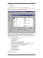
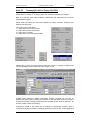
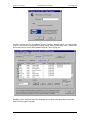
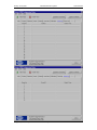
Screen dump of the test database program shown below: -
The test database program, which I designed & coded form scratch, give me a little practice
using Microsoft Visual C++ 6.0. This test database program may be small, but it give me a lot
of experience and knowledge, as this program made use of many basic features included in
visual C++, including dialog boxes, edit boxes, menu bar, tool Bar, list ctrl, buttons, combo,
Database (CRecordset & CDaoRecordset) AfxMessageBox and many more.
At the end of the week I felt I had gain a great deal of knowledge about programming with
Microsoft Visual C++ and was know capable of creating a number of small applications, while
just two weeks earlier I had no knowledge (had never used C++ before).
Week 14:
Monday 23/10/2000 to Friday 27/10/2000
Was given a copy of the existing database “Panel.mdb” created in Microsoft Access 95, since
my program must be backward compatible (e.g. must load the old databases), I started writing
the code to access the database through a visual C++ program, using the DAO database
interface. The reason why I used the DAO interface and not the ODBC Data Source
Administrator is because DAO lets you get direct access to the *.mdb file, and does not
require the data source to be added to the ODBC before hand, hens it is possible to select the
*.mdb file just as you would any other if the default path cannot be found or the user selects
open in the file menu. The existing database was large and complex, so it was going to take
some time to display all the appropriate views/tables.
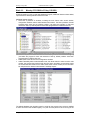
Most of the data is stored in a table called [tblSETTINGS], this table contains 135 columns
and at present 230 records, in order make life easy of the operator this table was split into 8
views (Commercial, System, Calibrate, Setpoints, Inputs, Outputs, Security, Main) a
Multidocument child window was required for each view.
BEng (Hons) Electronic Systems
Page 8
98425145
Sunday, 20 July 2003
Industrial Placement Logbook
Colin K McCord
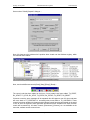
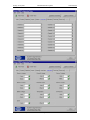
Using Combo boxes, Edit boxes, Check boxes, Radio Buttons, and many others the all eight
form view was designed and working, included a save function which saved changes to the
database. Also dialogs for adding, deleting, records where also added.
Security was high in importance; the database is to have a 3-level (DE, TE, Admin),
username and password security system, the existing database already had several tables,
which where for user control and monitoring. Table [tblusersstatus] contained the fields
“Username”, “Level”, “Status”, “Lastlogged”, and “Password Changed Date”. This table had to
be auto updated in the background without the users knowledge. The table [tblUSERHIST]
contains the fields “LastDate”, “LastUser”, “Issue”, “WON”, this table stores the user history,
e.g. every record the user views/modifies is store here, at present there are 2500 records.
These two tables where added to my program and automatic code to use/update these tables
was added.
Also by this time you needed a password & username to login, all usernames are stored in
the table [tblusersstatus]; the password was encoded onto the database using various
encoded techniques. Another option was to stored the password in the windows registry, but
this had the draw back that, that if the user when to a different machine there system would
no longer have a record of his/hers password, and this was ruled out early on. Storing the
password on the database meant that any user could use any computer, as the password
was not stored locally, put actually encoded onto the database.
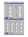
Because the system uses a 3 level security system, some users have restrictions imposed on
them, e.g. only users with level-3 Admin Access or the user who created the record in the first
place can delete it. Also starting working on a Class that viewed the User History/User List
table (including deleting/adding users), only level-3 Admin operators will have access.
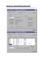
Screen dump of the main section show below: -
Week 15:
Monday 30/10/2000 to Friday 03/11/2000
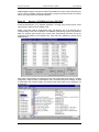
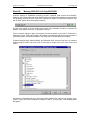
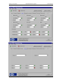
Added admin tools to database: • Display a list of all users.
• Display User History.
• Add a user.
• Edit a user.
BEng (Hons) Electronic Systems
Page 9
98425145
Sunday, 20 July 2003
•
•
Industrial Placement Logbook
Colin K McCord
Del a user.
Clear User history.
Only users with level 3 (Admin) Access will have access to the admin tools.
Screen shot of the admin section shown below, this is how it appears at present, will properly
be modify in the coming weeks, so the appearance may change: -
On Tuesday of this week, I attended the training course “Control Systems” in the CEC. The
course length was 7½ hours, and went into considerable detail on most of FG Wilson’s control
panels. Including Circuit diagrams, ISO standards, Price, Quality, functional description,
advantages, disadvantages, defects, components etc… control systems, looked at in detail
included: • Engine Interface Module.
• Starter Motor Solenoid (EIM SR)
• Glow Plug (pre-heat)
• Fuel Control Solenoid
• Safety relays
• 1001 Control System, (drawing D19443B)
• 2001 Control System, (drawing D20449A)
• LCP0, LCP1. LCP2 Control Panels (drawings D18494F, D20025B, D22640B)
• 4001 & 4001E Control Systems (drawing D18495G, D19516D)
• Ribbon/Field Cable Interface (drawing D22628C)
• Remote Annuciators
• Automatic Transfer Switches
• TC – Transfer Switch
• Mti – Transfer Switch
• Access 4000 Control Panel
• 6000 Series Control System
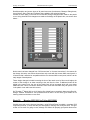
SCI Annuciator Data Frame: -
BEng (Hons) Electronic Systems
Page 10
98425145
Sunday, 20 July 2003
Industrial Placement Logbook
Colin K McCord
Created a test program in Turbo C 3.0 for dos, reusing old code form my Modbus test
program. The program was a small simple program compared to the Modbus test program, it
was designed to be small and simple to use. On the main menu the user has three choices
“Build”, “Baud”, “Quit”. The build section lets the user input a test data frame form the
keyboard the BCC is then calculated and added to the frame which is then transmitted
through COM1 at the current baud rate. The baud section lets the user select the baud rate,
9600 to 56K.
SCI Annuciator Frame format: SOI
SOI
ADDR
DATA
ENC
BCC
ADDR
DATA1
DATA2
DATA3
DATA4
DATA5
ENC
BCC
= 7Eh, start of information
= 30 – 3F, address 0 TO 15
= Binary data for channel 1 to channel 20
= Encoding information
= Block check sum, if SUM = ADDR+DATA1+DATA2+DATA3+DATA4+DATA5+ENC
then BCC is the one’s complement of the LSB of SUM
The encoding information is used to recover the received data. Because the SCI annuciator is
designed to work with GenAccess, some control characters like 0x01 (SOH), 0x06 (ACK),
0x10 (EOS), 0x18 (CAN), should be avoided to transmission. IF any data equals one of these
control characters, the data will be inverted and hence the corresponding bit in ENC is set to
1. The bit 7 in NEC is always set to 1 to ensure that it is not one of the control characters. The
bit 0 is to make sure BCC is not one of the control characters. If the calculated BCC equals
one of the characters, the bit 0 in ENC will be set to 1, and BCC is calculated again.
The content of ENC is as below.
Bit 7
1
Bit 6
DT5
Bit 5
DT4
Bit 4
DT3
Bit 3
DT2
Bit 2
DT1
Bit 1
0
Bit 0
BCS
DTn = 1, DATAn in the frame is inverted.
DTn = 0, DATAn in the frame is normal.
BCS = 1. The old BCC was one of the control characters (with BCS=1, it is not)
It is clear the SCI annuciator data frame is not as complex as the Modbus data frame, but it
does its job well. Unlike Modbus the communication between the access 4000 control panel
and the SCI annuciator is not bi-directional, (Modbus designed to work with up to 255 slave
devices) and a simple data frame is all that’s needed.
Week 16:
Monday 06/11/2000 to Friday 10/11/2000
Monday OFF – took my Second floating Holiday, still have 6 more floats to take before the
Christmas Holidays, It has been confirmed by my manager (Dr Ning Li) that I can move a
couple of days across to the new year, or take the money. The plan is a present that I take 3
more before the Christmas holidays and pass 3 days to next year.
Continued working on “Access 4000 control panel database” program, added “Export
Configuration File”, “Export Text File” and many small modifications.
The configuration file looks like this: CCC,1000102823,1,1,1,1,1,1,1,9600,4,14,17.5,50,4,3,96,4,380,1,8,300,7
,7,3,0,0,0,0,1.000,0,1.000,0,1.000,0,1.000,0,1.000,0,1.000,0,1.000,1,
1.000,0,1.000,1,242,5,2,1,198,5,2,1,55,5,2,1,45,5,2,1650,0,1199,0,2,1
,14.7,5,1,11.3,10,1,12,10,0,3.0,0,95,0,30,0,10,0,0,0,0,1,0,0,1,1,0,0,
1,1,0,0,1,1,0,0,1,0,0,0,0,1,1,0,1,0,1,1111,2222,2004,9999,@
BEng (Hons) Electronic Systems
Page 11
98425145
Sunday, 20 July 2003
Industrial Placement Logbook
Colin K McCord
It contains all the configuration setpoints stored in the database, and is downloaded directly
into the Access 4000 control panel. The file starts with ‘ccc’ and ends with ‘@’, this is always
the case. The individual setpoints are then separated by commas, e.g. 1000102823 above is
the SAP works order number and 9600 is the baud rate etc…
The text file, once exported is also downloaded directly into the Access 4000 control panel.
Each file starts with ‘TTT’ and ends with @, and messages are separated with commas. The
database a present contains 12 text files for 12 different languages (table [tblTextFile]); FRE,
DAN, ITA, DUT, NOR, SPA, POR, SWE, ENG, FIN, GER, ICE. The language that is selected
on the current record is exported. For example if the current record has ENG as its language,
when the user hits “export text” the ENG text file will be export, while if the current record has
GER as its language, the GER text file will be export.
Text file [ENG] TTT,
SCROLL TO A
,
MENU ITEM
, THEN PRESS ENTER ,
OVERVIEW*,
ENGINE*,ALARM LOG*,*GENERATOR,*CONFIGURE,*CONTROL ,V
…
Engine Temp
,Low Oil Pressure
,Fault Channel 1
,Fault Channel
2
,Fault Channel 3
,Fault Channel 4
,@
Text file[GER]: TTT,
MENUEEINTRAG
,
HERVORHEBEN
, UND ENTER DRUECKEN ,
UEBERS.*, MASCHINE*,ALARMBER.*,*GENERATOR,*KONFIG. ,*STRT.KONT,V ,A
…
,Nied.Oeldruck
,Fault Channel 1
,Fault Channel 2
,Fault
Channel 3
,Fault Channel 4
,@
The above text files are summarised as the full text file contains 182 messages / commas.
For both the “Export Configuration” and “Export Text” a standard file dialog was used: -
Week 17:
Monday 13/11/2000 to Friday 17/11/2000
Continued working on “Access 4000 control panel database” program, Added “import text
file”: -
BEng (Hons) Electronic Systems
Page 12
98425145
Sunday, 20 July 2003
Industrial Placement Logbook
Colin K McCord
This imports a text file into an existing or new language record.
Options dialog added this option dialog lets the user specific the default database, which will
be loaded automatically on start-up. The data is stored in an INI file, c:\Panel_config.ini, which
is loaded on start-up. If the default database does not exist or is not valid or the INI file does
not exist, the user is ask to select the database via a standard file dialog, and the INI is
updated / created.
Many other small improvements & bug fixes where made, some where visual improvements: -
BEng (Hons) Electronic Systems
Page 13
98425145
Sunday, 20 July 2003
Week 18:
Industrial Placement Logbook
Colin K McCord
Monday 20/11/2000 to Friday 24/11/2000
Continued working on the Access 4000 database program, additional features where added,
improvements to existing features where also made.
One additional feature was to restrict any record to one user at any one time; e.g. no two
users can access the same record at any one time. This was accomplished by locking records
that where in use by other users, an AfxMessageBox will appear with the message {“Sorry,
record: - \nWorks order / SAP number: " + ID + "\n\nIs being use by user: " + m_Pass>m_LastUser +"\n\nRecord is locked, try again later..}, if a users attempts to access an locked
record.
The records where locked by adding the record ID and User name, to a table specifically
designed for the task. Before the program moves to any records, its looks up this table and
checks that the record it was requested to move to is not locked. Upon logout the program
makes sure there are not any lock records by that user, if any are found they will be remove,
hence unlocking the records. The same occurs upon login, the reason for this is to make sure
there are not any lock records by that user, which could occur if the user did not logout
(Power cut/ Computer crash).
Another additional feature was to create a new record from an existing one (e.g. makes a
copy). The user clicks the tick-box at
the bottom of the dialog, once ticked
the combo-box below is activated and
the user selects the source record.
(The default selected source record will
be the current record). Once an
appropriate “Works Order Number” is
entered for the new record the OK
button is activated.
On OK: • If tick-box not ticked, new record
created with default values.
• If tick-box ticked, new record
created with all the values from the
source record (copy), except fields:
“Works Order Number”, “Date”,
“User”, “Last User” & “Issue”, which
will not be the same as the source
record.
The feature enable/disabled users was added, this feature lets admin users disable/enable
“level 1” & “level 2” users. If a user is disabled that user will not be granted access to the
system. An AfxMessageBox will appear saying “User profile disabled by Admin. Access
denied”. Locked users are added to table with CRC which validates that, the users are
disabled.
Other additional features included: • Save all dialog when main frame is closed.
• Close all multidocument windows when the main control window is closed.
• Print user history table & Print user lost table.
• Sense each user locks their current record, therefore the max number of users is equal to
total number of records. If there are already the maximum number of users logged in no
more are users will be granted access. This is unlikely to happen, as there are 60 users in
total and there are at present 230 records and its unlikely that the records count will
decrease but in-fact will probably increase.
Many small visual displays, bug fixes and performance improvements very made.
BEng (Hons) Electronic Systems
Page 14
98425145
Sunday, 20 July 2003
Week 19:
Industrial Placement Logbook
Colin K McCord
Monday 27/11/2000 to Friday 1/12/2000
Continued working on the Access 4000 database program, additional features where added,
improvements to existing features where also made.
Additional features include: • Save size & positions of windows, including the main frame, main control window,
configuration windows and the administration tools window. The size & positions of these
windows where save into the windows registry, just before the program is close and
restored on start-up. Default positions have been programmed for initial first time use.
•
•
•
Save size & positions of all toolbars and status bar, again stored in the windows registry
just before the program is close and restored on start-up, default positions have been
programmed for initial first time use.
Added Titles to the tile bars of all configuration windows.
Added Tractability table to administration tools, this allows Admin to select a works order
number, the program then looks through the user history and filters out everything expect
the records that are relevant to the select works order number. Select print on the menu
bar will printout the “Works Order Number Tractability Report”.
The default database was originally stored in an INI file; the program has now been modified
so that it is stored in the windows registry. If no path is found (will occur when running for the
BEng (Hons) Electronic Systems
Page 15
98425145
Sunday, 20 July 2003
Industrial Placement Logbook
Colin K McCord
first time) a File dialog appears and asks the user to select the default database file.
(Microsoft Access *.mdb).
Many other improvement and bug fixes where made.
Modbus
The Modbus protocol I developed, has now been released for sometime now, and there is an
official software upgrade available for all existing customers of the access 4000 control panel.
On Thursday I demonstrated the basic operation of the Modbus protocol, for customers that
where interested in making use of the Modbus protocol. The demonstration was carried out
using my Modbus test program, in the Genset test bays. The customers appeared to be
happy with the protocol (which passed all their tests) and plan to make use of the protocol, by
developing their own windows based software for controlling and monitoring the Genset. The
Modbus protocol is medium that lets communicate between the Access 4000 control panel
and their software application take place.
Week 20:
Monday 04/12/2000 to Friday 08/12/2000
I took three float holidays between Monday and Wednesday of this week.
Thursday was spent evaluating the control software for Access 4000 Modbus; it was
developed in China. They also stated that sometimes the response too a Modbus command
sent to the controller was too slow, normally the master should expect a response for a query
within 128ms. But as discovered when evaluating there control software, the average
response time is slow when the engine is running, and sometimes slower than 128ms.
The reason for a slower response when engine is running is because there is a lot of complex
calculations taking place and the processor is being pushed to the limit, as a result the
Modbus communication slows slightly, as it is a lower priory.
There is not much that can be done to improve the response time on the Access 4000 control
panel as it would require a faster processor, which is not an option at present. One solution is
to increase the timeout on Master control software to 150ms; this will reduce the number of
repeats.
The main problem was not the response time. When engine is running (only when engine is
running) exception error 0A (Gabbled Message) appears approx. 5% of the time, this occurs
because the processor is involved in complex calculations and sometimes it misses a
character (e.g. character fails to be added to the buffer). If there is a cap of more then 1.5ms
between character a timeout will occur and exception error 0A (Gabbled Message) will be
send to the master, then master will repeats the query. A some gap between commands will
reduce the change of this occurring, as It will give the processor in the control panel more
time to complete its calculations, store incoming characters in the buffer and respond to
Modbus commands.
Evaluation was complete, report written.
Also modifications were made to my Access 4000 control panel database program, they
included many small improvements in the program structure, making it more readable and
BEng (Hons) Electronic Systems
Page 16
98425145
Sunday, 20 July 2003
Industrial Placement Logbook
Colin K McCord
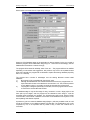
easier to modify. Plus serial number generation program was written, serial number check
and dialogue for user input were added to main database program.
The serial number generator, is a dialogue based MFC program, a password is required for
access to the program. After the correct password as been entered the dialogue shown below
is displayed: -
The user enters Name & Address, hits the [Generate] button and the 16-digit serial number is
generated, the serial number is depend on both the name & address and all fields are case
sensitive. This program is not for general use, but only for administrator use only; he/she will
generate a user or company license, which will then be passed on (not the program).
When the main database program start-ups it will check the windows register, for license
details if found, it will generate its own serial number form the name & address fields and
hence compare the generated serial number with the one stored in the windows registry.
If the generated serial number does not match the generated one, or there are no license
details (will occur when program first installed onto a machine) a dialogue box will appear
asking the user to enter user license details.
When OK is pressed the serial number is generated once again using the Name (Edit Box)
and the Address (Edit Box), once generated it is compared with the Serial (Edit Box). If they
match the license details are added to windows register and program starts as normal, else
BEng (Hons) Electronic Systems
Page 17
98425145
Sunday, 20 July 2003
Industrial Placement Logbook
Colin K McCord
AfxMessageBox appears saying that invalid license details have been entered and asking the
user to check for mistakes. If [Cancel] is pressed the program unloads and access to program
denied, until valid user license has been entered.
Week 21:
Monday 11/12/2000 to Friday 15/12/2000
Continued development of my database application, including many small bug fixes, visual
improvements, improved more readable code.
Added “Trace User” table to Administration tools, this allows a user to be selected then a
complete history of that user is displayed. The database [UserHistory] is used to generate the
table; the program goes through every record within [UserHistory] and filters out all the
records that are related to the selected user. Print code was updated for printing of this
additional table.
Page setup dialogue added. This dialogue lets the user modify page layout settings, including
configuration, margins (offset), administration Tools, orientation and printer settings. All data
is stored within the window’s registry with default values hard-coded into the application for
first time use.
BEng (Hons) Electronic Systems
Page 18
98425145
Sunday, 20 July 2003
Industrial Placement Logbook
Colin K McCord
Shown below is a screen shot of “Page Setup” dialogue: -
Stage one (The Database stage) of the application is almost compete, for the next couple of
weeks the program will be tested within are group (E11 – Electronic Control Design), with the
database file stored within a network drive [O].
The program will be tested for reliability, ease of use, etc… The program will then be modified
depending on test results and suggestions, this producer may have to be repeated several
times, but eventually the program will be released to replace the existing database (hopefully
within 1 to 2 months).
The program has a number of advantages over the existing Microsoft Access based
database: 1)
My program is fully compatible with the original *.mdb.
2)
Although the database file was created with Microsoft Access, the program does not
require Microsoft Access to be installed on the machine to run. The exe file at present
is only 380Kb in size; it is so small it can easily be executed from a floppy disk.
3)
The program is designed specifically for this task; hence the program is much easier
to use than the monster Microsoft Access.
The database stage is only the first stage of many, because it is such a large project it has
been split up into stages, and the program will be released at each stage, it could be
sometime before all stages are complete. The finished project will include: Internet TCP/IP
communication, which will let customers have access to the database from anywhere in the
world updating there data as required.
At present my job is to create the database stage (Stage 1) with easy readable code, as it will
be use as the bases, for any additional stages at a later date. The modifications may not be
completed my me, so its important that my coded is easy to read and contains lots of
comments.
BEng (Hons) Electronic Systems
Page 19
98425145
Sunday, 20 July 2003
Week 22:
Industrial Placement Logbook
Colin K McCord
Monday 18/12/2000 to Friday 22/12/2000
Developed a small dialogue based MFC program, for creating and editing access 4000 text
files. There is a dos program already in use, but a windows based application would be a
large improvement, so the go ahead was given to create a new windows based application.
The program was made as simple as possible, and designed for ease of use, the main control
dialog is shown below: -
The user can create a new text file by selecting ‘new’ from the File menu.
The user can select a text file in there ways: 1) Click the ‘Open’ Button.
2) Click the ‘Open’ menu item under ‘File’.
3) Drag a text file into the dialog window.
Once a text file has been selected, the user clicks the button Editor, for display & edit of the
selected text file.
The editor contains 7 pages, was contain all 181 strings used on the Access 4000 control
panel. The user can edit any string, which is saved directly to the text file when the [Apply] or
[OK] buttons or pressed.
BEng (Hons) Electronic Systems
Page 20
98425145
Sunday, 20 July 2003
Industrial Placement Logbook
Colin K McCord
The main use of this program will be in the creation of new languages, at present there are
12. The static labels will always be in English; hence using this as a guild you can translate
the text file into any alphabetic based language. A screen shot of the editor with FRE.txt
loaded show below: -
Screen shot of ‘about’ dialog shown below: -
The program is small only 100KB in size, its simple to use, and can easily be modify.
Finished for Christmas holidays, on Thursday 21 December.
BEng (Hons) Electronic Systems
Page 21
98425145
Sunday, 20 July 2003
Week 23:
Industrial Placement Logbook
Colin K McCord
Tuesday 02/01/2001 to Friday 05/01/2001
Started back on Tuesday 2nd of January 2001, after Christmas and New Year holidays.
Most of my time was spent making additions, modifications and improvement to my Access
4000 database program.
Spend some time making my code more readable, by adding comments, simplifying, and
deleting redundant code.
Four popup menus were added: 1) Right click on main control window.
2) Right click on Admin tools window.
3) Right click on Tool Bar.
4) Right click on any configuration window.
Added coded, to check for changes before closing the program, if changes are detected the
user will be asked if he/she wants to save the changes, or not.
Updated control buttons for loading configuration windows, previously say you click on
[System] the system section window will be created, or activated. Well I have now change it
so that if the window is already created and is the activated window, it will be destroyed. So
we have Create, Activate, then Destroy.
Changed the format of the buttons use for loading the configuration windows, when a
configuration window is activated, for example [system] the button system will be highlighted if
BEng (Hons) Electronic Systems
Page 22
98425145
Sunday, 20 July 2003
Industrial Placement Logbook
Colin K McCord
user selects or opens a different window the appropriate button will be highlighted. Also if the
use clicks on a highlighted button, the window associated with that button is close.
New Highlighted Buttons Screen Shot 1: -
New Highlighted Buttons Screen Shot 2: -
New Highlighted Buttons Screen Shot 3: -
BEng (Hons) Electronic Systems
Page 23
98425145
Sunday, 20 July 2003
Industrial Placement Logbook
Lots of key shortcuts where added: About
Alt+A
Copy
Ctrl+C
Close
Alt+C
New
Ctrl+N
Open
Ctrl+O
Options
Alt+O
Print
Ctrl+P
Print Preview Ctrl+Alt+P
PageSetup
Alt+S
Print Setup
Ctrl+Alt+S
Paste
Ctrl+V
Delete Rec
Alt+DELETE
Last Record
Shift+DOWN
Main
F1
Commerical
F2
System
F3
Calibrate
F4
Setpoints
Inputs
Outputs
Security
AdminTools
ToolBar
Statusbar
ConfigToolbar
Copy
Add
Paste
Prev Record
Next Record
First Record
Cut
Exit
Colin K McCord
F5
F6
F7
F8
F12
Alt+F1
Alt+F2
Alt+F3
Ctrl+Insert
Alt+Insert
shift+Insert
Shift+Left
Shift+Right
Shift+Up
Ctrl+X
Alt+X
Small modifications also made on my Text Editor program and serial number generator
program.
Week 24:
Monday 08/01/2001 to Friday 12/01/2001
Experimented with and then added owner drawn menus with bitmaps to may Access 4000
control panel database program. The purpose of using this was to mimic the menu style used
in Visual C++ 5.0/6.0 and MS Word. This was not easy, but after a couple of different
approaches managed to find a way to make it work.
The code was placed into a new Class and can be included into any MFC application, making
it easy to add bitmaps to menu items. The code can be reused over and over again.
Window Standard Menu
Owner drawn menu with bitmaps
All menus in my Access 4000 control panel database program including popup menus have
been replaced with these new owner drawn menus. I think it adds character to the program.
Below are screen shots of some of the menus within the program showing the new owner
drawn menus: Before
BEng (Hons) Electronic Systems
After
Page 24
98425145
Sunday, 20 July 2003
Industrial Placement Logbook
Colin K McCord
Before
After
Before
After
Before
After
Before
After
BEng (Hons) Electronic Systems
Page 25
98425145
Sunday, 20 July 2003
Industrial Placement Logbook
Colin K McCord
Experimented with then added hyperlinks to my Access 4000 control panel database
program, again code placed into separate Class which is included using #include. This class
allows you to add a hyperlink to any static text box, easily and quickly. Two lines of code are
all that is required, once the hyperlink class has been included into any MFC application.
Inside the class is code, to change the colour of the text to blue, underline, and change the
mouse pointer to a hand when the mouse hovers over the hyperlink. Screen shot shown
below: -
BEng (Hons) Electronic Systems
Page 26
98425145
Sunday, 20 July 2003
Week 25:
Industrial Placement Logbook
Colin K McCord
Monday 15/01/2001 to Friday 19/01/2001
Tasks for this week: 1) Write a computer program to generate serial number for GenAccess 1.1 control software.
2) Create Word document for printing disk labels for GenAccess 1.1 control software.
3) Print 50 sets (50 X 3 disks) of labels for GenAccess 1.1 control software.
4) To stick labels onto 150 floppy disks.
5) Copy GenAccess1.1 control software onto the disks.
6) Test all sets by installing GenAccess1.1 control software.
7) Write quick start guide on how to operator the generator and print labels.
Screen shot from my Serial Generator for GenAccess 1.1: -
Generating, saving, and opening serial numbers
¾
Click [Generate] to generate a new serial number, this new serial number will be added to
the serial list and appear in the SN edit box. The generated serial number is directly
related to the current system time & date, with an added 8-bit CRC. The edit box ‘Next’
shows the counter for the next serial number to be generated; this field is incremented
automatically after generation of every serial number. The user is permitted to modify the
‘Next’ edit box (Note. If a serial number all ready exists with the same counter value as
the one being generated, the generated serial number will NOT be added to the list).
¾
Click [Save As] or [Save] to save a generated serial list. [Save As] will always ask the
user for a filename, while [Save] will save changes to an existing file or ask the user for a
BEng (Hons) Electronic Systems
Page 27
98425145
Sunday, 20 July 2003
Industrial Placement Logbook
Colin K McCord
filename if current list is unsaved. Standard window’s ‘save’ dialogue is used for saving
new serial lists.
¾
Click [Open] to load a previously saved serial list, standard window’s ‘open’ dialogue will
appear to allow the user to select the file easily. Generated GenAccess1.1 serial lists will
have the extension ‘gsl’ (eg SerialList.gsl), only files of this type will be displayed in the
open dialogue making life easier for the user.
¾
Clicking [New] will clear the serial list. Warning program does not check for changes if
user has not saved the existing serial list, that list/changes will be lost forever.
Decoding serial numbers
¾
All serial numbers generated by this program are directly related to the system time &
date. So it is possible to decode a serial number, to find out the date & time it was
generated. Click [Decode SN] to open the decode dialogue show below: -
¾
Type the serial number that you want to decode into the ‘Serial Number’ edit box, then
click [Decode]. The serial number has now been decoded and the edit boxes ‘Counter’,
‘Date’ and ‘Time’ will show the results. Because the serial number contains an 8-bit CRC
it is possible to check the serial number is valid, if valid the serial number was properly
decoded correctly. If the CRC is invalid the serial number may not be decoded correctly,
this will occur if there is a type mistake in serial number or this program did not generate
the serial number (e.g. serial number 1 to 200 were not generated with this program and
cannot be decoded).
Exporting serial numbers
¾
First, set the starting position and the number off serials you wish to export. For example
if starting position was 201 and number off was 50, serials 201 to 250 will be exported. If
the tick box ‘All > Starting POS’ is ticked, the edit box ‘No OFF’ will be disabled and all
serials after the starting position will be exported.
¾
Next, type in a filename into the ‘Filename’ edit box for best result include the extension
*.txt. Or click [Browse…], which will allow you to enter your path and filename using the
window’s standard ‘save’ dialogue.
BEng (Hons) Electronic Systems
Page 28
98425145
Sunday, 20 July 2003
¾
Industrial Placement Logbook
Colin K McCord
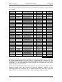
Next, Select the format: All Fields
Gen. Serial
----------201-Q9TWHBBC
202-Q9TWHBA9
Counter
------201
202
Date
----
Time
----
15/01/2001
15/01/2001
11:51:23
11:51:23
Full Serial Number
-----------------GA1-201-Q9TWHBBC
GA1-202-Q9TWHBA9
Serial Only
GA1-201-Q9TWHBBC
GA1-202-Q9TWHBA9
Serial X3
GA1-201-Q9TWHBBC
GA1-201-Q9TWHBBC
GA1-201-Q9TWHBBC
GA1-202-Q9TWHBA9
GA1-202-Q9TWHBA9
GA1-202-Q9TWHBA9
¾
Next, Click [Export] the file will be created and notepad will load automatically if the
extension *.txt was used.
Creating & printing disk labels.
¾
Load the Microsoft Word document ‘GenAccessV2.doc’, note: the Microsoft Excel
spreadsheet ‘Data source.xls’ should load automatically.
¾
The document uses a technique known as mail merge. Disk numbers, Serial numbers,
and Part numbers are stored in the Microsoft Excel spreadsheet and merged with the
word document when printed.
¾
The document deals with 8 sets (24 disks) at once, using 3 A4 label sheets. Make sure
printer is on manual feed, or 3 A4 label sheets have been inserted into the feeder tray.
¾
Export serials using format ‘Serial X3’ and No. OFF ‘8’, then cut & paste the serials
directly into the Serial number column in the ‘Data source.xls’ spreadsheet.
¾
From the word document ‘GenAccessV2.doc’ click the icon
(Merge
printer). 24 labels should now be printing using the imported serial numbers
BEng (Hons) Electronic Systems
Page 29
to
98425145
Sunday, 20 July 2003
Industrial Placement Logbook
Colin K McCord
How the serial number is generated
The serial number is generated using tables of codes, which are direct related to the date & time
of the system, hence the date & time can be decoded at a later date. The codes are letters or
number, which I tried to pick a random. These codes are stored in arrays in the computer
program hence coding and decoding can easily be achieved.
Serial Number Counter
#
#
#
-
Month
#
Year
#
Date
#
Year
2000
2001
2002
2003
2004
2005
2006
2007
2008
2009
2010
2011
Code
Q
9
A
8
Z
6
W
7
S
5
X
2
Year
2012
2013
2014
2015
2016
2017
2018
2019
2020
Other
Code
1
O
P
L
M
N
3
2
T
0
Min
1-2
3-4
5-6
7-8
9-10
11-12
13-14
15-16
17-18
19-20
21-22
23-24
25-26
27-28
29-30
31-32
Code
Z
X
C
V
B
N
M
0
9
8
7
6
5
4
3
2
Min
33-34
35-36
37-38
39-40
41-42
43-44
45-46
47-48
49-50
51-52
53-54
55-56
57-58
59-60
0
Code
1
P
O
I
U
Y
T
R
E
W
Q
L
K
J
H
Code
N
B
V
C
X
Sec
31-32
33-34
35-36
37-38
39-40
Code
Z
2
4
6
Q
Sec
41-42
43-44
45-46
47-48
49-50
Month
1
2
3
4
5
6
7
8
9
10
11
12
Code
Q
G
K
U
O
P
5
D
J
K
3
6
Date
1
2
3
4
5
6
7
8
9
10
11
12
13
14
15
16
Code
P
L
M
O
K
N
I
J
U
H
B
Y
G
V
T
F
Date
17
18
19
20
21
22
23
24
25
26
27
28
29
30
31
Code
C
R
D
X
E
S
Z
W
A
Q
7
6
8
9
4
Sec
1-2
3-4
5-6
7-8
9-10
Code
A
S
D
F
G
Sec
11-12
13-14
15-16
17-18
19-20
Code
H
J
K
L
M
Sec
21-22
23-24
25-26
27-28
29-30
Min
#
Hour
#
Sec
#
8-Bit CRC
#
#
Hour
0
1
2
3
4
5
6
7
8
9
10
11
Code
E
M
N
B
V
C
X
Z
L
K
J
H
Hour
12
13
14
15
16
17
18
19
20
21
22
23
Code
G
F
D
S
A
P
O
I
U
Y
T
R
Code
W
E
R
T
Y
Sec
51-52
53-54
55-56
57-58
59
0
Code
U
I
O
P
8
3
‘GA1-‘ is added to the front of generated serial number. (GA1-###-########).
I successfully competed and tested 50 Set of GenAccess 1.1 control software, where the serial
numbers for each set were created using my serial generation program. Using mail merge the
labels where easily printed once the design of the document was complete.
The serial generation program has been written so that it is easy to use, and easy to export the
serials into excel and in turn merge with the labels document. 4 page Quick Start Guide has been
written explaining in detail how to operate the program, and print the labels.
BEng (Hons) Electronic Systems
Page 30
98425145
Sunday, 20 July 2003
Industrial Placement Logbook
Colin K McCord
The Hyperlink class I wrote last week was reused, screen shot below: -
Week 26:
Monday 22/01/2001 to Friday 26/01/2001
Experimented with serial communications using Microsoft Visual C++ 6.0, example code was
found on the Internet, soon I was able to send and receive characters. I also discovered direct
access to the hardware is not allowed under Windows NT. Interaction with the serial port was
achieved through a file handle and various WIN32 communication API’s. This method is Windows
95 compatible.
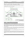
I decided to create a small windows based master program for the Access 4000 control panel,
using my Modbus protocol. GenModbus workspace was created using MS Visual C++ MFC
wizard.
Started adding code to initialize the communications, then function to read & receive a character.
Created a real time timer, which by default will be called every 50ms. This function will contain the
protocol for transmitting queries and receiving responses. The first time the timer is called the
Modbus query for read all controls is transmitted (1,1,0,0,0,10,3D,C6). The next time the timer is
called the RX buffer is checked to see if a character has been received, if no character has been
received nothing happens and the function returns. This can happen a max of three times (50ms
x 3 = 150ms timeout) then the query frame will be transmitted again. One a character is received,
the reset of the response frame is received and checked, if valid the received data is added to the
BEng (Hons) Electronic Systems
Page 31
98425145
Sunday, 20 July 2003
Industrial Placement Logbook
Colin K McCord
array table[n]. Next query for Status \ Alarms etc… Below shows the basic operation of the timer
function: Void Timer(); /* Called every 50ms */
{
switch(m_state)
{
case TX_CONTROLS:
Build and transmit Modbus query frame for reading all controls.
Limit = 0;
m_state = RX_CONTROLS;
Break;
case RX_CONTROLS:
if (char has bee received)
{
Receive & decode Modbus response frame and if valid
add data to Table[n]
m_state = TX_ALARMS;
}
else
{
limit = limit + 1;
if ( limit > 3) m_state = RX_CONTROLS
}
Break;
Case TX_ALARMS:
Build and transmit Modbus query frame for reading all Alarms.
Limit = 0;
m_state = RX_ ALARMS;
Break;
case RX_ ALARMS:
if (char has bee received)
{
Receive & decode Modbus response frame and if valid
add data to Table[n]
m_state = TX_ MONITORING;
}
else
{
limit = limit + 1;
if ( limit > 3) m_state = RX_ ALARMS
}
Break;
case TX_MONITORING:
...
case RX_ MONITORING:
...
case TX_CONFIG:
...
case RX_CONFIG:
if (char has bee received)
{
Receive & decode Modbus response frame and if valid
add data to Table[n]
m_state = TX_CONTROLS; /* Complete loop
}
...
break;
}
}
BEng (Hons) Electronic Systems
Page 32
98425145
Sunday, 20 July 2003
Industrial Placement Logbook
Colin K McCord
This meant that constant communication can be achieved, net step was to display the table[n] on
the screen updating the display every time it’s changed. Created a new muliti-doc template called
“Address Allocation Table”, this window displays the table in it raw form. See screen shot below: -
On Thursday 25th of January I attended an internal training course “Material Master Creation /
Amendment – Cources for Engineers”. Length 2 hours, which showed how to Create / modify
Material Master records in SAP. Included a practical exercise: Fill out material master creation
form for item 7 & 11d on drawing MGS3687A.
Added configuration dialogue to GenModbus.exe, see screen shot bellow: -
Started work on a mulitidocument view for viewing the panel configuration.
BEng (Hons) Electronic Systems
Page 33
98425145
Sunday, 20 July 2003
Week 27:
Industrial Placement Logbook
Colin K McCord
Monday 29/01/2001 to Friday 02/02/2001
Monday to Wednesday off took three floating holidays.
Thursday, continued working on my windows based monitoring program for Access 4000 control
panel using my Modbus protocol, which I developed and tested, several months ago. This
program is for test proposes only and will properly not be released to the outside world, as the
Modbus protocol on Access 4000 was designed for customers to develop there own programs
easily.
The only test program FG Wilson currently has for testing the Modbus protocol on Access 4000
control panel is the dos program I developed many moons ago, this program is very low level and
only an engineer could understand how to operated and understand what happening. Again this
program was not designed for customer use, but customers in Hong Kong needed a test program
and my small dos test program was sent.
Once communication protocol was complete and tested using my mbpc.exe program running on
a laptop (PC simulation of the Access 4000 Modbus protocol). Using RS232 link, the programs
communications were checked, the address allocation table on the mbpc.exe have been set to
pre-programmed values, so the first thing was to check that the windows application received the
whole table correctly. After a view modifications the monitoring communication using a timer has
been tested to work correctly. Also checked that the communication did not crash when
communication was lost, the protocol worked as designed and continued communication as soon
as it was reestablished.
Next added 4 additional views, for viewing the received information at a high level, hence any
body can understand quickly and easily what happening: 1)
2)
3)
4)
Generator Overview, e.g. Phase A,B,C Voltage, Line AB, BC,CA Voltage, etc…
Status / Alarms Overview, e.g. General Alarm, High Bat Voltage, Low Bat Voltage, etc…
Power Overview, e.g. Total kW, Total kVr, Total KVA, etc…
Panel Setpoints & Configuration, e.g. High frequency setpoint, Low frequency setpoint, etc…
These four additional views take the data directly of the array Table[n], which is filled by the
communication protocol.
Screen Shot of Generator Overview: -
(The above screen shot was taken when connect to an actual Access 4000 control panel, but it
was not connected to an generator, or simulator box at this stage, that will be tested next week)
BEng (Hons) Electronic Systems
Page 34
98425145
Sunday, 20 July 2003
Industrial Placement Logbook
Colin K McCord
Screen Shot of Status / Alarms Overview: -
(Digital signals, either 1 or 0. Highlighted = logic 1, e.g. “Heart Beat” was at logic 1 when this
screen shot was taken)
Screen Shot of Power Overview: -
(All fields are double-byte numbers expect for “Total kWh” which is a 32-bit number, it is blank on
the screen shot because this feature was disabled on the Access 4000 control panel)
The program can tell that the “Total kWh” feature is disabled when it’s high word is equal to
FFFFh, if disabled the program displays nothing in the edit box.
The “Panel Setpoints & Configuration” view displays the current values of all the setpoints
configurable in the access 4000 control panel, also a button [Change] beside every setpoint,
when clicked a dialogue box appears which allow the user to change the value of that setpoint.
BEng (Hons) Electronic Systems
Page 35
98425145
Sunday, 20 July 2003
Industrial Placement Logbook
Colin K McCord
Screen shot of Panel Setpoints & Configuration shown below: -
Added Modify setpoint Dialogue, communication is stopped when the dialogue is opened and
started again when closed. If the setpoint value is change and OK or APPLY are hit, the program
communicates with the Access 4000 control panel and requests that the setpoint should be
changed to the new value.
If timeout occurs the program tries again, this will happen a maximum of 5 times. After 5 times an
error message will be displayed in the dialogue box, and had been pressed to dialogue will not
close. If setpoint was updated successfully, a message saying so is also displayed and if [OK]
was pressed the dialogue will close.
The dialogue uses a combo box to select setpoints, user can stay in the dialogue and change a
number of setpoints by selecting them on the combo box, changing there value and press [Apply].
If the user hits the [Select] button on the “Panel Setpoints & configuration” view beside a setpoint,
that setpoint will be selected automatically when the dialogue is loaded.
BEng (Hons) Electronic Systems
Page 36
98425145
Sunday, 20 July 2003
Industrial Placement Logbook
Colin K McCord
Screen shot of “Modify Setpoint” dialogue: -
Note: All views save the window size & position when closed onto the Windows registry, which
are restored when loaded: -
Next, need to add Genset controls [Start], [Stop], [Estop], [Reset]: -
The control code has been added to the timer, 8 more states have been added: TX_START,
RX_START, TX_STOP, RX_STOP, TX_ESTOP, RX_ESTOP, TX_RESET, RX_RESET.
If timeout occurs the query message will be repeated, this will happen a max of 3 times and state
will move back to TX_CONTROLS. If successful state moves back to TX_CONTROLS. These
controls have been tested on the laptop and the [Reset] control has also been tested on the panel
it self, all work as expected. When generator simulator becomes available next week the other
control will be tested fully. All views, Controls, [Disconnect], [Connect], etc. are available on the
menu bar, toolbars and the context menu.
BEng (Hons) Electronic Systems
Page 37
98425145
Sunday, 20 July 2003
Industrial Placement Logbook
Colin K McCord
Screen shot of context menu show below (note my bitmap menu code from my database program
has been reused): -
Screen shot of main toolbar shown below: -
Note hyperlink code from my Access 4000 database program has also been reused: -
BEng (Hons) Electronic Systems
Page 38
98425145
Sunday, 20 July 2003
Week 28:
Industrial Placement Logbook
Colin K McCord
Monday 05/02/2001 to Friday 09/02/2001
Continue working on GenModus monitoring program, improved code structure and reliability.
Added an icon on the status bar which flashes green then yellow when Modbus communications
are operating correctly the Icon is red when in disconnect mode. If communication fails the icon
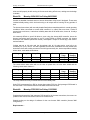
will not flash. Screen shot of the status bar below: -
Program was tested on Access 4000 control panel using hardware simulator to simulate the
Genset. The program works fine, no problems found yet!
There is another change of plan; the program will now be placed on the web for customers to
download hence a small help file had to be created. It was decided that the program will make a
good test program, and will be available to the customers of Access 4000 free of charge.
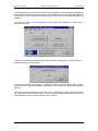
Created a help file using “Help Workshop” and “Microsoft word”, this is the first time I’ve created a
windows help file and it took some time to learn how to compile such a file. See Screen shot
below: -
All Windows, Dialogues and menu items are directly linked to the help file; for example if you
press F1 when the “COM Configuration” dialogue is active. The help topic “COM Configuration2
will appear.
BEng (Hons) Electronic Systems
Page 39
98425145
Sunday, 20 July 2003
Industrial Placement Logbook
Colin K McCord
Thursday & Friday was spent in the electronic lab. Helping to carrier out voltage transient tests on
the new CI panel. It had previously fail some of these tests at Queen University Belfast; we were
checking the modifications made worked.
The first test was to send these voltage transient signals through the main voltage input on the CI
panel, each transient test lasted for 1 minute. Tests included: ¾ +1kV transient on Ground line.
¾ -1kV transient on Ground line.
¾ +1kV transient on Live.
¾ -1kV transient on Live.
¾ +1kV transient on Neutral.
¾ -1kV transient on Neutral.
¾ +2kV transient on Ground line.
¾ -2kV transient on Ground line.
¾ +2kV transient on Live.
¾ -2kV transient on Live.
¾ +2kV transient on Neutral.
¾ -2kV transient on Neutral.
The CI panel continued working as normal at 1kV, at 2kV RS485 communication died, but
recovered when voltage transient was stopped. No permit damage was caused to the CI panel
during any of these tests.
Next, using a coupling clamp all external cables were subjected to these transient signals. Cables
tested included RS485, AutoDialer faults and the telephone cables (both Autodialer and modem).
In every case the coupling clamp was charged to 1kVolts, both Positive and Negative signal
where tested. RS232 (GenAccess) to RS485 (Access 4000) communication slowed when voltage
transient signals were active but recovered as soon as each test was complete.
Large voltages such as 1kVolt & 2kVolt signals where being used, hence it was vital to follow
strict safety producers. CI panel did not pass all tests first time, modifications where made and
tests repeated until it passed. The CI panel will be tested officially on Saturday at Queens
University Belfast. Production cannot start until the CI panel passes all of these tests, if any fail it
could hold back production for weeks.
Week 29:
Monday 12/02/2001 to Friday 16/02/2001
Started work on a small dialog based windows program, propose of which is to load *.txt and
*.S19 files to the Access 4000 control panel. There already exists a dos version called load.exe,
but for it to work correctly you must leave Windows. The communication protocol used is
extremely simply compared with Modbus, plus I had a copy of the source code form the MS dos
load.exe.
Using the source code from the MS dos load.exe as a guild I started to write the communication
protocol for sending Text and S19 files. The communication protocol for text and S19 files differ
so it was important to detect, which was being sent.
The text file communication protocol was really simple; it consisted of sending the text file out in
one large block then waiting for ACK once complete. The S19 (main code) file communication
protocol was also simple; it consisted of sending the S19 file out in 80 byte blocks, waiting for
ACK after every block. If timeout occurs or NAK the last block is repeated, max number of NAKs
is 10 (then error message to many NAKs will be displayed) and max number of timeouts is 5.
The baud rate used is 9600bps, 1 stop bit, and no party. This format is fixed and cannot be
change, reliability is more important than speed. It takes about 4 min 30 seconds to load 220Kb
S19 file (Access 4000 – Ver 1.19K), about 5 second for 3195 byte language text file and about
BEng (Hons) Electronic Systems
Page 40
98425145
Sunday, 20 July 2003
Industrial Placement Logbook
Colin K McCord
1.5 seconds to load 336 bytes configuration text file. Note the text files; both configuration and
language files can be exported directly form my Access 4000 database program, also my Access
4000 text editor can be used to edit or create new language text files.
Screen shot of main dialog shown below: -
The program was designed to be simple to used, the user first needs to specify the S19 or TXT
file to load to the Access 4000 control panel. There are four ways to specify the file: 1.
2.
3.
4.
Type filename and path into combo box.
Click [Browse…] and select filename using standard Windows open dialog.
Combo box contains last 5 files, select using downward arrow.
Drag file into dialog.
Next, user reboots the Access 4000 control panel and while in bootstrap mode user clicks [Load],
loading dialog appear and file starts to load.
The last 5 files are stored in the Windows registry, screen shot below: -
The loading dialog using progress meter shows the percentage complete during the loading
process, also the bytes send and total number of bytes are also shown. Screen dump below: -
BEng (Hons) Electronic Systems
Page 41
98425145
Sunday, 20 July 2003
Industrial Placement Logbook
Colin K McCord
If load was successful the [Cancel] button is change to [OK] and the [Retry] button remains
disabled. If load was unsuccessful the [Rety] button is enabled.
The about dialog: -
Program tested on Access 4000 control panel, and after a view modifcations the program seems
to work fine. The computer I’am using is running Windows NT and has a PIII proccessor with
128MB of RAM, so it was important to test on other operating systems and older PCs.
Started testing on Windows 95 running on P133 with 32MB of RAM, S19 files worked fine, but I
had a problem with the text files. At about 50% the communication slowed and the Access 4000
control panel timeout and load failed. At frist I did not understand why this was happening, but
then discoved that I was incrementing the process bar after every byte hence creating a delay
between the bytes. The reason why the S19 files works was because there is a delay between
blocks when waiting for the ACK, hence the processor was able to catch up.
Once it was discovered what was causing the problem, the problem was easily fixed. The solution
was to change to step size of the processor bar to 50, and step it every 50 bytes instead of every
one. This solution worked fine. Although there was no problem with the S19 files, it is bad and
wasteful programming to increment the process bar after every byte. The process bar was
updated after every block, hence no delay between bytes within a block.
Before the changes where made, loading S19 files on my computer (PIII – Windows NT) used
10% of the processor, it now uses 2% of the processor. Before the changes where made, loading
TXT file on my computer (PIII – Windows NT) used 45% of the processor, it now uses 4%. These
values where taken from the “Window NT Task Manager”.
Created a small help file using “Help workshop” describing how to operated the program. After a
couple more hours of testing, I passed the program file to another team member who will test it.
He will go about his normal tasks, and if he requires to load TXT or S19 files to the Access 4000
BEng (Hons) Electronic Systems
Page 42
98425145
Sunday, 20 July 2003
Industrial Placement Logbook
Colin K McCord
control panel my program will be used. If program has been proven to run reliably, it will replace
the existing MS dos version.
Sometime in the future the bootstrap code in the Access 4000 control panel will be modified to
allow uploading as well as downloading. My program can easily and quickly be modified to
accommodate any new features, as they’re required.
On Thursday,
There a customer in Saudi Arabia was having a problem with the Oil Pressure (variations), they
where using Access 4000. The customer was told to put a resistor across the Oil Pressure pins
on the Access 4000 control panel, and if a constant value of oil pressure was displayed there was
nothing wrong it the Access 4000 control panel. The customer try this and a problem with the
Access 4000 control panel was ruled out.
The customer was given a number of possible solutions; one included putting a 0.1uF capacitor in
parallel with the oil pressure sender. But the customer wanted use to test the possible solutions.
FG Wilson has sold this type of Gensets all over the world and never had any problems with the
oil pressure before, so in order for us to fix the problem we need to be able to recreate it.
So I was given the task of finding a Genset in Larne with the same problem, and if one could be
found investigate. Took a walk to bay F (Genset test bay), asking the technicians if they had
come across this oil pressure problem during testing. They had never had a problem with the oil
pressure, they seamed to think that the problem was a faultily oil pressure sender.
There is not a Genset in Larne with the same problem; hence we cannot test any of the possible
solutions. Email explaining this was sent, and they will have to try to fix the problem themselves
using are suggestions as a guild.
Week 30:
Monday 19/02/2001 to Friday 23/02/2001
Carried out some work on the new SCI Annunciator, this is a redesign of the existing Access
4000 – remote SCI Annuciator. Using RS422 communications, the Annunciator can display up to
20 faults (e.g. Low Battery Voltage, High Battery Voltage, High Frequency, Low Frequency
etc…). The Annuciator only receives the information it does not transmit, so only two of the
communication cables are required RX+ and RX-. As well as the 20 LEDs for the faults there is
another one that flashes On/Off when communications is working, also there is a “lamp test” push
switch which when pressed all LEDs light. The push switch also shuts off the buzzer when an
alarm is active.
A PIC is used, for the prototype stage this PIC contains flash memory which can be changed as
many times as necessary, when in production the PICs used will have PROM memory (write
once) the program cannot be changed. The main reason for not using flash in production is cost.
We need to have two prototypes ready for the end of the week, so was given the task to check
both prototype PCB boards making sure there are no broken tracks. This was achieved using
multimeter in buzzer mode, using schematic as a guild checked every connection. Next after it
has been confirmed that the PCB are correct, I started to populate both boards with all their
components, hence getting some much needed soldering practice.
After the boards had been finished, I tested them. Connected to 12V-power supply, connect RX+
and RX- to TX+ and TX- of the Access 4000 and switched on. I noticed straight away that a view
LED’s where constantly on, using mulitmeter it was discovered that a couple of BS170 transistor
BEng (Hons) Electronic Systems
Page 43
98425145
Sunday, 20 July 2003
Industrial Placement Logbook
Colin K McCord
where dead (Always a circuit between collector and emitter). Replaced faulty transistors and
tested again, both prototype SCI Annunciation where working.
There was a slight worry the voltage regulator will over heating (mounted to small heat sink) a
high voltages. I left the SCI Annuciator running on 28 Volts for 6 hours, to seek how hot this
voltage regulator got. After 6 hours there was a small amount of heat, but the heat sink seamed
to be doing a good job in displacing the heat and the tested was seen as a success.
Next using AutoCAD R14, I design label strips. These label strips are inserted behind the main
label displaying in English each fault. Next given the task to get a rough price of all the
components using RS I priced each component, which where then added for a total.
Week 31:
Monday 26/02/2001 to Friday 02/03/2001
Started to write the technical report for my Access 4000 database program. The Access 4000
database program I have created is only the first step of many. At a later date Internet
communications and other functions will be added, another engineer will properly complete these
future modifications. So it’s important that the code is easy to read, with a fixable programming
structure. The technical report is to make life easier for any engineer who wants to modify the
database program; it will contain a detail description on every class with a brief description of
each function.
I completed the detailed description of each class along with a brief description of each function: CMainFrame
CPanelApp
CPanelDoc
CPanelView
CAdminToolsView
CAboutDlg
CAboutSerialNumberDlg
CAddNewRecord
CAdmin_SelectUserDlg
CAdminAddUserDlg
CAdminEditUserDlg
CAdminSelectWonDlg
CChangePassDlg
CDeleteRecDlg
CImportTxtDlg
COptionsDlg
CPageSetupDlg
CPasswordDlg
CCalibrateView
CCommercialView
CInputsView
COutputsView
CSecurityView
CSetpointsView
CSystemView
CPanelSet
CTextFileSet
CUserHistSet
CUserStatusSet
BEng (Hons) Electronic Systems
Page 44
98425145
Sunday, 20 July 2003
Industrial Placement Logbook
Colin K McCord
Detail description and screen shots of all panel resources (Accelerators, Bitmaps, Dialog boxes,
Icons, Menus, String Table and Toolbars) where added to the technical reported.
Carried out more work on the new SCI Annunciator, design changes where made to the plastic
cover. Using AutoCAD R14 changes were made to the design of the plastic face, see screen shot
below: -
Notice name has been changed from “SCI Annunciator” to “Access Annunciator”, the reasons for
the change is that the new remote Annunciator only works with the Access 4000 control panel. It
is foreseen that it will also be compatible with the new Access 3000 control panel, which is at the
early stages of development.
These design changes included increasing the size of the metal cover by 20mm at all edges, the
reason of this change is to allow mounting to the wall from the front. 4 additional holes will be
drilled in the metal cover; the size of the plastic face will be increased which will cover these
additional holes. Hence if customer whishes to front mount the Annuciator they can punch a hole
in the plastic cover and insert their screws.
On Thursday 1st March 2001 at 14:30 had my first visited from my academic placement officer Mr.
George Jackson. Answered a view questions and he filled in a few forms, give details on his
marking scheme and written course work.
Week 32:
Monday 05/03/2001 to Friday 09/03/2001
Carried more work on the Access Annuciator, using RS and Farnel compiled a complete PCB
component price list, in each case the price was taken if ordering 100+ at anyone time. This give
a idea on how much it’s going to cost, although FG Wilson will properly get special discounts so
BEng (Hons) Electronic Systems
Page 45
98425145
Sunday, 20 July 2003
Industrial Placement Logbook
Colin K McCord
the actual price is almost certain to be less than my estimated price. Below is a copy of the price
list I complied: Part Number
Name
Description
Qty.
Comps
Price
Total (Price X
Qty)
237-7100 (RS)
0.1uF
CAPACITOR CERAMIC
11
£0.04
244-3825 (RS')
10-WAY IDC
RIBBON CONNECTOR
2
c1-c4, c7-c11, c14,
c17
EC3-4
214-1002 (RS)
100 - 5% - TR4
100R TR4 METAL OXIDE FILM 5%
1
R29
£0.08
228-6903 (RS)
100UF 50V
CAPACITOR ELECTROLYTIC
2
C12-13
£0.08
140-530 (RS)
10K - SIL9
RESISTOR NETWORK 9-WAY
7
R21-26, R31
£0.15
214-1024 (RS)
150 - 5% - TR4
150R TR4 METAL OXIDE FILM 5%
1
R27
£0.08
148-556 (RS)
1K6 - 5% - TR4
1K6 TR4 METAL OXIDE FILM 5%
21
R1-20, R32
£0.02
251-732 (FA)
1N4007
DIODE
1
D1
£0.02
211-4909 (RS)
33PF - 5% - S2
33PF 100V COG ML CERAM 5%
2
C15 - 16
£0.16
214-1210 (RS)
3K3 - 5% TR4
3K3 TR4 METAL OXIDE FILM 5 %
1
R28
£0.08
220-4658 (RS)
PCB CONNECTOR
1
EC1
£0.67
492-917 (FA)
4 - WAY
KLIPPON
4MHZ CRYSTAL
£0.47
£0.66
£0.08
£0.15
£1.05
£0.08
£0.50
£0.02
£0.32
£0.08
£0.67
FARNELL 492-917
1
X1
£0.33
228-1532 (RS)
41.P06P120A
IMO PIEZO SOUNDER
1
ALM
£1.94
672-385 (FA)
6-WAY HARWIN
FARNELL 672-385
1
X1
£0.29
325-727 (FA)
6N135
OPTO - ISOLATOR DIP-8
1
ISO1
£0.50
217-5695 (RS)
74HC595
8 BIT SHIFT REGISTERS
3
U4 - 6
£0.52
382-140 (FA)
74HCT165N
8-BIT SHIFT REGISTER
4
U1 - 3, U10
£0.23
166-2227 (RS)
750 - 5% - TR4
750R TR4 METAL OXIDE FILM 5%
2
R91 - 92
£0.18
103-0771 (RS)
91F08
DIP SWITCH 8-WAY
4
SW1-4
£0.53
336-747 (RS)
9633CD
MORS SWITCH SPNO
1
SW5
£1.15
932-840 (FA)
BS170
MOSFET N-CHANNEL
22
Q1 - 22
£0.09
192-0983 (RS)
DDE105S05
DC-DC CONVERTER 5V - 5V
1
REG2
£7.51
415-014 (RS)
FUSEHOLDER
FUSE-HOLDER
1
F1
£0.18
590-547 (RS)
HLMP4700
LED RED 5MM LOW CURRENT
20
L1 - 20
£0.25
590-553 (RS)
HLMP4740
LED GREEN 5MM LOW CURRENT
1
L21
£0.25
298-8508 (RS)
L7805ABV
5V, IAMP REGULATOR
1
REG1
£0.33
244-0624 (RS)
MAX3082
RS-485/422 TRANSCEIVER
1
U8
£1.13
324-3115 (RS)
MM74HC04
HEX INVERTERS 6 OFF
3
U9, U11 - 12
£0.15
1
U7
£1.74
£0.33
£1.94
£0.29
£0.50
£1.56
£0.92
£0.36
£2.11
£1.15
£1.94
£7.51
£0.18
£5.00
£0.25
£0.33
£1.13
£0.45
£1.74
TOTAL
£31.78
328-2429 (RS)
PIC16LC63A04I/P
(FA) = Farnell, (RS) = RS Catalogue
PIC MICROCONTROLLER
£0.33
My Access 4000 database program has been given out to a few engineers to use in replace of
the existing database program, any problems, bugs, or suggestions will be relayed to me. This
trial period may last a couple of months; any required changes to the program will be made. Once
test period is over and all problems are fixed the program will be released and a copy of the
program will be given to all concerned.
Finished Access 4000 database program technical report, the report was 60 A4 pages in length
(excluding source code) and contains all technical information required by any
engineer/programmer to understand how my program works quickly and easily. Using this
technical report as a guild he/she will be able to modify the program, quickly and easily.
BEng (Hons) Electronic Systems
Page 46
98425145
Sunday, 20 July 2003
Industrial Placement Logbook
Colin K McCord
Added a number of additional topics including; Front Cover, Introduction, Data Flow Diagram,
Data flow paths, Class structure, Class Description, Appendix 1 - *MDB data source description,
Appendix 2 – Hierarchy Chart, Appendix 3 – CDaoRecordSet Class Members.
The data flow diagram shows how data is transferred throughout the program, it was drawn in
AutoCAD Release 14, screen shot is shown below: Data Source (Panel.mdb)
Table
Table
Table
[tblTextFile]
[D2726h/001]
[tblSETTINGS]
[tblUSERHIST]
[tbluserstatus]
3
2
Table
5
4
1
Table
Program
CUserStatusSet
9
10
15
CCalibrateView
CCommercialView
CAdminToolsView
CAdmin_SelectUserDlg
16
CInputsView
12
COutputsView
CSystemView
8
18
CAdminAddUserDlg
CAddNewRecord
CChangePassDlg
17
CSetpointsView
14
CPanelView
13
CSecuirtyView
20
CUserHistSet
19
CPanelSet
11
6
CPassWordControlSet
7
CTextFileSet
CAdminEditUserDlg
CPanelDoc
CAdminSelectWonDLg
CDeleteRecDlg
Output / Input
Text File
Configuration File
Printer
Access 4000 Database - Technical Report
Colin K McCord
Electronic Control Department
Week 33:
08 March 2001
Data Flow Diagram
Rev
1.1
Page 2
Monday 12/03/2001 to Friday 16/03/2001
Cleaned up source code for my Access 4000 control panel program, adding additional commits
and simplifying the code. Also a view minor modifications very made most of which improve
speed, the database is quite large and is stored on a network drive, network drives are much
slower than the hard drives. Startup time was decreased by half just by making the code more
efficient, improvements made through the program. A bug that caused the program to crash was
discovered and fixed.
After all the modifications very made, the source code was added to a 3½ floppy disk along with
the source code for the serial generator. This disk was then stuck to the back of my technical
report, which was then filed (Current program version is 1.99a).
Small amount of work was carried out on my GenModBus program, Access Annuciator, Access
4000 and the new Tel Panel.
Access 3000 is in the early stages of development (Technical Specification not finished) it will be
somewhere in between the Access 2000 and Access 4000. It will be cheaper and have fewer
features than the Access 4000, but be more expensive than the Access 2000 but have more
features.
BEng (Hons) Electronic Systems
Page 47
98425145
Sunday, 20 July 2003
Industrial Placement Logbook
Colin K McCord
My task was to think of several methods of configuration the panel. The access 4000 has a
configuration text file that is exported from a database, which is then loaded to the controller
using load.exe. This file is very low level and cannot be easily be modified manually.
Possible methods for configuring of Access 3000: 1. Download configuration file using load.exe, while controller is in bootstrap mode
or/and maincode. The configuration will be exported form a database.
2. Upload panel configuration to a file using load.exe, while controller is in bootstrap
mode or/and maincode. This file can then be imported back to the database.
3. Download panel configuration directly from the database. The database program will
have included COM communications (user will select “Export to Access 3000”).
4. Upload panel configuration directly to the database. The database program will have
included COM communications (user will select “Import from Access 3000”).
5. Configure panel in real-time. Communications Protocol could be included in the
maincode. Activated by the user selecting it from within the menus of the controller or
the controller is able to automatically leave GenAccess or Modbus when a certain
signal is received and return when configuration is complete.
Configure panel in real-time
Windows based program displays current configuration, when the user changes a setpoint a
communication message block is sent automatically updating the setpoint. There is continuous
communication with the program and the controller at all times, if communication is
stopped/unreadable for a certain period of time the controller will leave this configuration mode
(return to Modbus or GenAccess).
This program will come in useful for customers without access to the database.
This program should also be able to: ♦
♦
♦
Upload and Download Configuration files.
Upload and Download Language files.
Download maincode.
All this functions should be included in one program with a user-friendly interface and must be
easy to use. Maybe consideration should be taken on including these functions in future versions
of GenAccess.
Security is very important, it recommended that some sort of password is used to protect the
remote configuration of any panel (maybe level 3).
Example Access 3000 configuration text file: [ID Block]
Works Order Number = D2336A/001
[System]
Communication = 1
Unit Address = 1
Data Speed = 9600
Comms = 4
BEng (Hons) Electronic Systems
Page 48
98425145
Sunday, 20 July 2003
[Calibrate]
VT Phase A Offset
VT Phase A Gain =
VT Phase B Offset
VT Phase B Gain =
[Setpoints]
Voltage High
Voltage High
Voltage High
Voltage High
Industrial Placement Logbook
Colin K McCord
= 0
1.000
= 0
1.00
Status = 1
Setpoint = 457
Time = 5
Action = 2
[Inputs]
[Outputs]
[Security]
Level 1 Password = 1111
Level 2 Password = 2222
Level 3 Password = 2004
Remote Password = 9999
Similar to Windows INI files, this has on main advantage over the Access 4000 configuration text
files: ♦
Customers can easy modify the setpoints without any technical knowledge, then load
the modified configuration to their controller.
But there is one disadvantage the file cannot be directly transmitted to the controller; it must be
simplified at the PC end before transmission. Hence the code in the load program is more
complex.
It is foreseen that the seam load program can load access 4000 and access 3000 text and S19
files, seen its not as simple as transmitting the access 3000 configuration directly you must be
able to detect which your sending. Access 4000 text files already have conheaders of CCC and
TTT, which can be used to detect existing Access 4000 files, different conheaders will be added
to the top of the access 3000 text file.
It is also possible to change the access 4000 text file to a similar format, without changing the
bootstrap code. The text file will be in the new high level format, the load program detects that the
file is a new access 4000 text file and converts it back to the old format and stores it in a CString,
which is then transmitted.
Load program should be able to: ♦ Upload Access 4000 and Access 3000 S19 Maincode files.
♦ Upload and Download Access 4000 existing formatted text files.
♦ Upload and Download new Access 4000 high-level text files.
♦ Convert between old and new access 4000 configuration text files.
♦ Upload and Download Access 3000 text files.
I’ve also drawn a few high level flowcharts for possible communication protocol for uploading and
download access 3000 configuration text files. Some screen shots show below: -
BEng (Hons) Electronic Systems
Page 49
98425145
Sunday, 20 July 2003
Industrial Placement Logbook
Colin K McCord
Start
How the Configuration file is Transmitted: Byte[0x00] = 'C'
Byte[0x01] = 'C'
Byte[0x02] = 'C'
Byte[0x03] = EEPROM_Table[0x00]
Byte[0x04] = EEPROM_Table[0x01]
Byte[0x05] = EEPROM_Table[0x02]
...
Byte[0x202] = EEPROM_Table[0x1FF]
Byte[0x203] = CRC High Byte
Byte[0x204] = CRC Low Byte
Byte[0x205] = '@'
Configuration file similar to windows INI file format, for example: [ID Block]
Works Order Number = D2336A/001
Transmit request to send
configuration file
[System]
Communication = 1
Unit Address = 1
Data Speed = 9600
Comms = 4
Access 3000 will store incoming characters into temp array (byte[n]). byte[0 to
2] checked for "CCC", CRC calculated and compared with byte[0x203] &
byte[0x204]. If CRC OK byte[0x03 to 0x202] will be copyied to EEPROM
Address table.
[Calibrate]
VT Phase A Offset = 0
VT Phase A Gain = 1.000
VT Phase B Offset = 0
VT Phase B Gain = 1.00
Wait for ACK
(Timeout in 250ms)
Timeout
[Setpoints]
Voltage High Status = 1
Voltage High Setpoint = 457
Voltage High Time = 5
Voltage High Action = 2
[Inputs]
[Outputs]
Transmit Configuration
File
(With added 16-bit CRC)
Wait for ACK
(Timeout in 5 Sec)
[Security]
Level 1 Password = 1111
Level 2 Password = 2222
Level 3 Password = 2004
Remote Password = 9999
Timeout or NAK
Stop
Access 3000 - Concept Design
15 March 2001
Config COM Protocol DL
Colin K McCord
Electronic Control Department
A3k_Cfg1.dwg
Start
Transmit request to
receive panel
configuration
Timeout
Wait for ACK
(Timeout in 250ms)
Receive configuration
and store incoming
characters in temp array
Stop
Check
CRC
Bad CRC
Send ACK
Access 3000 - Concept Design
Colin K McCord
Electronic Control Department
BEng (Hons) Electronic Systems
Page 50
16 March 2001
Config COM Protocol UL
A3k_Cfg2.dwg
98425145
Sunday, 20 July 2003
Week 34:
Industrial Placement Logbook
Colin K McCord
Monday 19/03/2001 to Friday 23/03/2001
Populated the final prototype Tel Panel PCB board, getting more soldering experience. After
completion of the population of all PCB components, I was involved in the testing of the PCB
board this included, testing the communications (RS232 to RS422) using my does CI test
program which I design 6 months ago.
After the communication passed, the auto-dialer was tested. Then using GenAccess software and
Access 4000 controller, the Tel panel was tested in detail: ♦
♦
♦
Using Modem communications at baud’s 9600bps, 19200bps, 32768bps.
Direct link RS232 to RS422 at baud’s 9600bps, 19200bps, 32768bps.
Direct link RS232 to RS485 at baud’s 9600bps, 19200bps, 32768bps.
All tests were successful; hence design modification made for VT noise resistance did not affect
the operation of the Tel Panel. Also proves that I soldered all components in the correct place,
using only the schematic diagram as a guild.
The reset of the week was spent playing around with a view new concepts in visual C++,
including custom controls. I designed a sample customs analogue meter for use for my
GenModbus application. Created a copy of my GenModbus application and modified the copy,
the reason is that visual effects are time consuming and I will properly not have time to complete.
This is really just an experiment to gain more knowledge on how to create custom graph oriented
controls, screen shot below: -
Other Experiments include: ♦
♦
♦
LED displays
Resizing of controls
Pie charts.
BEng (Hons) Electronic Systems
Page 51
98425145
Sunday, 20 July 2003
Week 35:
Industrial Placement Logbook
Colin K McCord
Monday 26/03/2001 to Friday 30/03/2001
Design of relay board PCB for Access 4000/3000 remote Annunciator, each relay board will have
8 relays. The remote Annuciator has two ribbon cable sockets each can control 8 relays, the relay
board must be designed so that the same relay board can be used for faults 1 - 8 and 9 – 16.
5 Volt relay are used, using a 5V regulator (L7805ABV) the voltage operating range of the relay
board is 7.5 to 30 Volts. Logic signals from the Annunciator are fed into a transistor (BS170)
which in turn switches on the relay: hh
Constructed and tested the design in the electronics lab, the design work well so the circuit
diagram was now finalized and design of the PCB can start. There was a small fault discovered in
the software of the Annunciator, normally when an alarm is active the appropriate LED flashes on
and off. But this is no good for use with the relay board, as the relay will also switch Off and On.
The solution was to modify the PIC software to read one of the spare digital switches on the
Annuciator PCB. If Switch = 1 for solid LEDs hence solid relay Switch = 0 for flashing LEDs.
Both the schematic and PCB will be design, using CADstar for windows 3.0. Two days were
spent learning and getting familiar with this powerful application.
Some time was spend in coming with some why of keeping the relay and annuciator active during
cranking, originally a small circuit was design for the relay board with would allow a 9V pp3
battery to power the relay board and Annunciator. But this idea was abandoned because the
BEng (Hons) Electronic Systems
Page 52
98425145
Sunday, 20 July 2003
Industrial Placement Logbook
Colin K McCord
current consumed by the each relay is 50mA; there are 8 relays on each board (two board can be
used), hence 8 x 50mA = 400mA X 2 = 800mA, Annunciator takes 200mA. Hence 1 A is required
form the battery, for the worst case scenario. Good quality PP3 battery can deliver 500mA, so it
would not be up to task. The Annuciator case is compact and a larger battery would be two large.
It was decided to leave it, if the customer experiences problem with the relays dropping out during
cranking they can use a separated power supply to power the Annuciator. This problem will not
occur in most cases, it may occur when the Annuciator is a long distance from the Generator
(1000s Meters) hence there will be a large voltage drop across the line and the Annuciator will
power down (At About 6 Volts). Hence no signal to relays and relay will drop out even though
their drop out voltage is 5% of there rated voltage.
Also this week I generated 50 more serial numbers for GenAccess 1.1 software application using
my serial generation program I wrote in January. 150 disk labels were then printed using the mail
merge technique.
Week 36:
Monday 02/04/2001 to Friday 06/04/2001
Started design off the PCB, the first thing was to set the size of the board. It was decided that the
board will be 165mm by 60mm, and it would have two electrical layers for routes. Then spent
some time positioning the components on the board, marking sure that there are no physical
problems. Originally I had the 5 V regulator at the top of the board but later move it to the bottom
as I did not like it to be close to the ribbon cable incase the ribbon cable started to melt.
After I had the components placed were I wanted them I started to manually route the tracks,
using thick 50/25 tracks for GND, VCC, Relay terminals and thin 15/10 tracks for signals. Once all
routes were completed using “Design Rules Check” all routes were checked for errors: Route to Route
Pad to Pad
Route to Pad
Pad to Via
Route to Via
Via to Via
Copper to Copper
Neck/Unneck Seg Too Short
Route to Copper
Pad to Copper
Thin Route Segment
Via to Copper
Isolated Copper
Route Offset
Drill Holes too close
Route to Board Outline
Pad to Board Outline
Via to Board Outline
Copper to Board Outlin
Comp Copper to Board Outline
Teardrop to Board Outline
Comp Copper to Route
Comp Copper to Pad
Comp Copper to Via
Comp Copper to Copper
Comp Copper to Comp Copper
Text to Comp Copper
Text to Copper
Text to Pad
Text to Via
Text to Route
Teardrop to Comp Copper
Teardrop to Copper
Teardrop to Pad
Teardrop to Via
Teardrop to Route
Teardrop to Text
Teardrop to Teardrop
Text to Text
Incomplete Routing
Text to Board Outline
Any errors found were fixed and error check compiled again to confirm. Other automatic checks
include “Electrical Rules Check”, “Connection Check” and “Design Comparison”. Once all routes
were routed without errors, copper ground plane was added to the top electrical layer. Automatic
BEng (Hons) Electronic Systems
Page 53
98425145
Sunday, 20 July 2003
Industrial Placement Logbook
Colin K McCord
check carried again after ground plane was added to make sure it no to close to routes other than
GND.
Bottom Layer
Top Layer
Notice that I’ve tried to keep the components grouped together, every component in a group of
components is the same value.
The spool file used for manufacture of the PCB board will be sent away next well. It will take at
least a week for the boards to arrive (5 prototype board will be ordered). When they arrive I will
populate them with components and will be involved in the testing producer.
I have gained a new skill, creation of schematic and PCB drawings using CADstar for windows
3.0. A nice break from software, enjoyed every minute.
The following report were generated in CADstar: -------------------------------------------------------------------------------Board Status Report
Cadstar Design Editor Version 3.0
Design:
D:\Work\COLINM~1\Projects\SCIANN~1\RELAYB~1\RELAY41.pcb
Design Title:
BEng (Hons) Electronic Systems
Page 54
98425145
Sunday, 20 July 2003
Industrial Placement Logbook
Colin K McCord
Cadstar PCB Design - 16 Layer Defaults
Date:
Time:
Friday, April 06, 2001
3:25 PM
-------------------------------------------------------------------------------Min
Max
Total
Number of components
59
59
Number of Testpoints
Area of components (sq.cm)
57.902
57.902
Component/board density
58
58
Number of equivalent 16 pin ICs
11
11
Area per equivalent IC (sq.cm)
9.109
9.109
-------------------------------------------------------------------------------Area
X length
Y length
(sq.cm)
(cm)
(cm)
Board outline
100.200
6.000
16.700
-------------------------------------------------------------------------------All
Min
Max
Total
Number of pads
177
177
Number of Testpoint pads
-------------------------------------------------------------------------------Layer pair codes
Number of vias
(Through Hole)
1
Total
1
-------------------------------------------------------------------------------Nets
Mixed width nets
Connections
Total number
51
124
-------------------------------------------------------------------------------Unrouted Unrouted Stapled
Routed
Routed
Conns Segments
Conns
Necked Unnecked
Widths
Segments Segments
Signal 50/25
Signal 15/10
VCC 50/25
GND 50/25
161
294
61
105
Total
621
Percentage of routed connections to total connections
100
-------------------------------------------------------------------------------Component
Unrouted
Route
Route
Layer
Copper
Copper Teardrops Segments Segments
Length
(cm)
Top Elec
2
308
132.579
Top Assembly
Top Glue Spot
Top Paste
Top Placement
Top silk
Top Solder Resist
No tracks
No vias
Universal ARD
GND
Sig 2
Sig 3
Sig 4
Sig 5
Sig 6
Sig 7
Sig 8
Sig 9
Sig 10
Sig 11
Sig 12
Sig 13
VCC
Bottom Elec
313
161.085
Bottom Assembly
Bottom Glue Spot
BEng (Hons) Electronic Systems
Page 55
98425145
Sunday, 20 July 2003
Industrial Placement Logbook
Bottom Paste
Bottom Placement
Bottom silk
Bottom Solder Resist
Doc 1
Doc 2
Doc 3
Doc 4
Doc 5
Doc 6
Doc 7
Doc 8
Doc 9
Doc 10
Doc 11
Doc 12
Doc 13
Doc 14
Doc 15
Doc 16
Unassigned
Total
2
Colin K McCord
621
293.664
-------------------------------------------------------------------------------Layer
Text
Errors
Figures
Areas Templates
Top Elec
Top Assembly
Top Glue Spot
Top Paste
Top Placement
Top silk
Top Solder Resist
No tracks
No vias
Universal ARD
GND
Sig 2
Sig 3
Sig 4
Sig 5
Sig 6
Sig 7
Sig 8
Sig 9
Sig 10
Sig 11
Sig 12
Sig 13
VCC
Bottom Elec
Bottom Assembly
Bottom Glue Spot
Bottom Paste
Bottom Placement
Bottom silk
Bottom Solder Resist
Doc 1
26
13
Doc 2
26
13
Doc 3
26
13
Doc 4
26
13
Doc 5
26
13
Doc 6
26
13
Doc 7
26
13
Doc 8
26
13
Doc 9
26
13
Doc 10
26
13
Doc 11
26
13
Doc 12
26
13
Doc 13
26
13
Doc 14
26
13
Doc 15
26
13
Doc 16
26
13
Unassigned
26
13
Total
26
13
-------------------------------------------------------------------------------All
Min
Max
Total
Number of test lands
-------------------------------------------------------------------------------End of report
BEng (Hons) Electronic Systems
Page 56
98425145
Sunday, 20 July 2003
Week 37:
Industrial Placement Logbook
Colin K McCord
Monday 09/04/2001 to Friday 13/04/2001
Given the task to design a small dos program to allow the test engineers to easily test the
communications of every Access Annuciator made. The program needed to be simple to
operated; hence there are only 3 items on the main menu.
Screen shot of main menu below: Access Annuciator Test Program
--------------------------------Start -- hit 1
Help -- hit 2
Quit -- hit Q
Screen shot of help screen shown below: Help
-------Usage: 1) Connect COM1 to RS232 side of the ADAM converter.
2) Connect Access Accunciator to RS485 side of the ADAM converter
eg RX+ (Annunciator) to TX+ (ADAM), RX- (Annuciator) to TX- (ADAM).
3) Connect power supply to both ADAM converter and Access Annuciator.
4) Power up the power supply.
5) Run AnnTest.exe from PC.
6) Hit 1 to start testing procedure.
Three tests
1) All LEDs
2) All LEDs
3) All LEDs
are carried out: Solid On.
Quick Flash - Shutdown fault.
Slow Flash - Alarms.
Program Information: Ver:
1.05
By:
Colin K McCord
Date:
09/04/2001
Department:
Electronic Control
Copyright:
(C)2001 FG Wilson (Engineering) Ltd
Hit [Anykey] to return to main menu
The communication protocol used in the Access Annuciator is extremely simple when compared
to such protocols like Modbus and GenAccess. The Annuciator only receives data it does not
transmit; hence only 2 of the 4 wires are used from the RS485 communications.
When the user hits [1] the first of three tests are carried out: Test 1 - All LEDs Solid On (Switch On)
---------------------------------------* Check all LEDs are Solid On
Hit [AnyKey] to continue...
If Annuciator communications are working correctly all LEDs should now be on.
Test 2 - All LEDs Quick Flash (Shutdown Fault)
-----------------------------------------------* Check all LEDs are flashing Quickly
* If buzzer sounds reset using switch.
Hit [AnyKey] to continue...
If Annuciator communications are working correctly all LEDs will be flashing quickly.
BEng (Hons) Electronic Systems
Page 57
98425145
Sunday, 20 July 2003
Industrial Placement Logbook
Colin K McCord
Test 3 - All LEDs Slow Flash (Alarms)
------------------------------------------* Check all LEDs are flashing slowly
Hit [AnyKey] to Finish
If Annunciator communications are working correctly all LEDs will be flashing slowly.
When user hits [Anykey] to finish a communication block is sent to switch off all LEDs and main
menu appears. The program is design to be small, easy to use, and reliable.
Order components from RS required for 5-prototype relay boards, after Easter I will build and test
the relay boards.
Carried out detail costing of Access Annunciator including: ♦
♦
♦
♦
♦
♦
Week 38:
Cost of PCB Components
Cost of PCB
Cost of populating PCB with components
Cost of case
Cost of Screws, bolts, nuts and washers.
Cost of optional relay board, including; components, PCB, Bolts, nuts, washers, and
10-way ribbon cable.
Monday 23/04/2001 to Friday 27/04/2001
5 PCB relay boards arrived, along with the components I ordered from RS. Checked every relay
board PCB with multimeter, making sure there were no broken tracks or design errors. Populated
all 5 relay boards with components, getting some soldering practice.
After two relay board prototypes had been constructed, they were connected to a prototype
Access annuciator so operational tests could be carried out. Each relay was turned on one by
one using my Access annuciator test program, and normally closed and normally open pins were
checked using a mulitmeter in buzzer mode.
The relay functioned properly, and the other three boards were completed. Next was reliably
testing, this involved leaving all relays on and checking that they where still work after a long
period of time.
Using a hand drill I drilled 8 holes on the back of the Access annuciator box, these holes were for
mounting of two relay boards. Two relay boards were screwed into place and connected to the
Access annuciator via 10-way ribbon cables. The Access annuciator, which is mounted on the lid
of the box, was connected to a power supply with communications connect to my PC via RS232
to RS485 converter.
The power was switched on and using my Access annuciator test program all 16 relays were
switched on. Power supply voltage was then increased to 28 volts (worst case condition for the 5Volt voltage regulator 7805).
After some time the voltage regulators and relays had become very hot, but seemed to be stable
as the temperature didn’t get any hotter as time went on (Heat sink working well). After 8 hours
the annuciator and relay boards (still hot) will still operating correctly. This test was carried out
BEng (Hons) Electronic Systems
Page 58
98425145
Sunday, 20 July 2003
Industrial Placement Logbook
Colin K McCord
twice and will properly be left running all of next week during office hours, making sure the design
is reliable.
Week 39:
Monday 30/04/2001 to Friday 04/05/2001
Carried out detailed functional tests on Access Annunciator relay board I designed. These tests
included reliably testing, which involved turning on all relays and left running for long periods of
time.
The Access Annunciator (with two relay boards fitted) where tested beyond their normal operating
conditions. When connected to access 4000 controller it is unlikely that more than 5 faults at
anyone time would occur, I carried out reliability tests with all 20 faults active, hence all 16 relays
were active.
It’s extremely difficult to get all 20 faults to occur using the Access 4000 controller, hence the
Access Annunciator was connected to my PC using RS232 to RS485 converter. My Access
Annuciator test software (Advanced version) I developed a couple of months ago, was used to
active all alarms.
Voltage was set at 29 volts, and the Annunciator with all 16 relays active, was left to run
constantly for up to 8 hours. This was repeated several times, afterwards the relay boards and
Annuciator where still working as normal. But it did get extremely hot, hence temperature reading
where taken; result table shown below: Voltage
Relay B1
Relay B2
Current
Hours
29.40
29.40
29.40
All 8 ON
4 ON
4 ON
All 8 ON
4 ON
All 8 OFF
580 mA
410 mA
280 mA
8
4
2
Room
Temp
26.5oC
26.3oC
26.3oC
Temp.
Reading
63.6oC
51.4oC
39.2oC
The results above were taken with no air holes on plastic box, air holes were added and the
following results were obtained: Voltage
Relay B1
Relay B2
Current
Hours
29.40
29.40
29.40
All 8 ON
4 ON
4 ON
All 8 ON
4 ON
All 8 OFF
580 mA
410 mA
280 mA
8
4
2
Room
Temp
26.8oC
26.3oC
26.3oC
Temp.
Reading
53.0oC
39.4oC
32.2oC
The relay boards were fully functional after all of the reliably tests.
Order PCB components from RS for Access Annunciator PCB, the final prototype PCB board is
due next week. I will build and test the new board sometime next week.
Week 40:
Monday 07/05/2001 to Friday 11/05/2001
Populated and tested the final prototype PCB board for the Access Annunciator, there were no
problems and Access Annunciator is due to be released soon.
Started working on the design of software for the new Access 3000 controller (Access 3000
configuration).
Requirements: -
BEng (Hons) Electronic Systems
Page 59
98425145
Sunday, 20 July 2003
Industrial Placement Logbook
Colin K McCord
Configuration is conducted during bootstrap. There are four main functions: ♦ Export main code to flash memory.
♦ Export configuration file to serial EEPROM.
♦ Import configuration to PC.
♦ Export TEXT file to flash memory.
On the PC side each function is performed using batch mode communication, i.e. each function
can be started by selecting Export Main Code, Export Configuration File, Import Configuration file
etc.
During bootstrap if ‘M’ or ‘C’ or ‘U’ or ‘T’ is received 5 times, the software goes to one of the
defined functions. When the function is completed, the software enters Configuration State that
allows the user to perform another function.
The configuration software should be well structured for future modification. Since remote
configuration using modem will be included, the corresponding program block should be inserted
as a dummy function.
Calibration program and database function may be required to be included in the future, so the
software structure should be flexible to accommodate these applications.
Spend most of the week thinking about the program and how to make the operation of the
program as easy as possible (Easy to use user interface, hence no training required for users).
Jotted down a couple of rough idea on paper, spending a lot of time thinking about the program
structure and flexibility.
Week 41:
Monday 14/05/2001 to Friday 18/05/2001
Continued working on the design of the configuration program for the new Access 3000
controller. At this early stage of development I concentrated on program structure and layout. All
the communications will be stored in the same dialog class, and can be inserted directly into any
program.
I played around with dialogs trying to design and simple easy to use program. Screen dump of
the man dialog shown below (Note: at this early stage dialog may change): -
BEng (Hons) Electronic Systems
Page 60
98425145
Sunday, 20 July 2003
Industrial Placement Logbook
Colin K McCord
The first and main tab is the “Load” tab this section is simpler to the Load program I designed for
Access 4000. I felt that this was a good idea, as my load program is used widely throughout the
world, hence when the user sees this program for the first time he/she is already familiar with the
operation.
The other Tab “Apps” contains applications, which experience operators can make use off.
Screen dump below: -
All the communications will be stored in one dialog and will be called from a number of different
locations. Screen shot shown below: -
The program will have direct access to a database, which I will design and program. Program
structure must be flexible and readable. I spent some time thinking on the design of the program
structure.
This project is a large one and will take some time to complete, the Access 3000 controller is in
the early stages of development, hence I will also need to design a test program to test the
communications running on laptop connect to PC via RS232.
BEng (Hons) Electronic Systems
Page 61
98425145
Sunday, 20 July 2003
Week 42:
Industrial Placement Logbook
Colin K McCord
Monday 21/05/2001 to Friday 25/05/2001
Continue working on my configuration program for the new Access 3000 controller.
I developed a function that could encrypt or decrypt a string up to 500 characters long. It uses a
128-bit key and without this key it is almost impossible to decrypt and encrypted string. This
function can be used in any program and will be very us
CString CA3KApp::Cryptor(unsigned long *const Pass, CString str, bool Encipher)
unsigned long *const Pass - pointer to 128-bit password
CString str - string to encrypt/decrypt.
bool Encipher - true for encrypt, false for decrypt
Encrypted or decrypted string is returned.
It uses the tiny encryption algorithm; this algorithm is one of the fastest and most efficient
cryptographic algorithms in existence. David Wheeler and Roger Needham developed it at the
Computer Laboratory of Cambridge University. It is a feistel cipher, which uses operations from
mixed (orthogonal) algebraic groups – XORs and additions in this case. It encrypts 64 data bits at
a time (8 characters) using a 128-bit key.
It is highly resistant to differential cryptanalysis, and achieves complete diffusion (where a one-bit
difference in the plain text will cause approximately 32 bit differences in the ciphertext) after only
six rounds (I use 32 rounds). Performance on a modern desktop computer or workstation is very
impressive.
For example: unsigned long pass[4];
pass[0] = 0xFF1287EA; /* 128 bit key – cannot decode with this key */
pass[1] = 0x12345678;
pass[2] = 0x64944953;
pass[3] = 0x37552745;
CString temp;
temp = Cryptor(pass,"This is a test,",true);
temp will equal: 0odzz0x18l9wi81u3bf1n0kln7g4
This function will be used to for passwords, serial numbers, etc…and will be used in my
programs.
Also worked on the layout and
program structure of the
configuration program, trying
to make it as flexible as
possible. Created a view
dialogues to view a possible
structure. Added three level
password control system to the
program along with all the
code to make it work (using my
new encryption function to
store passwords in the window
registry).
BEng (Hons) Electronic Systems
Page 62
98425145
Sunday, 20 July 2003
Industrial Placement Logbook
Colin K McCord
Carried out some work on the database section, creating a dialogue layout and implementing
code for user profiles and passwords including adding, editing, and deleting users. Some code
was reused from the Access 4000 database program, hence saying time.
Database section will be the last to be completed, but it’s about to like about the structure and
make sure the program can cope.
BEng (Hons) Electronic Systems
Page 63
98425145
Sunday, 20 July 2003
Industrial Placement Logbook
Colin K McCord
Screen dump of Add User Dialogue: -
Screen dump of configuration section on database dialogue: -
BEng (Hons) Electronic Systems
Page 64
98425145
Sunday, 20 July 2003
Week 43:
Industrial Placement Logbook
Colin K McCord
Monday 28/05/2001 to Friday 01/06/2001
Continue working on my configuration program for the new Access 3000 controller.
Wrote the communication protocol for uploading the main code: switch(state)
{
case WaitforResponse:
case BldPkt:
/* read a line from file */
case SendPkt:
/* send out the packet */
case WtPktAk:
/* wait for ACK */
case PktAkTmo: /* packet timeout */
case NkPkt:
/* receive NAK */
case ProcEnd
case Cancel:
/* error, abort operation */
}
Designed dialogs for editing panel configuration, screens shot in the following pages: -
Little code for has been added yet, I’m just playing around with ideas and trying to design a
flexible structure. Screen shot of the ‘Misc’ tab shown above.
BEng (Hons) Electronic Systems
Page 65
98425145
Sunday, 20 July 2003
BEng (Hons) Electronic Systems
Industrial Placement Logbook
Page 66
Colin K McCord
98425145
Sunday, 20 July 2003
BEng (Hons) Electronic Systems
Industrial Placement Logbook
Page 67
Colin K McCord
98425145
Sunday, 20 July 2003
BEng (Hons) Electronic Systems
Industrial Placement Logbook
Page 68
Colin K McCord
98425145
Sunday, 20 July 2003
BEng (Hons) Electronic Systems
Industrial Placement Logbook
Page 69
Colin K McCord
98425145
Sunday, 20 July 2003
Industrial Placement Logbook
Colin K McCord
Started work on an MS dos based test program, which will test the communications of the above
program. The reason why I needed a test program is that the Access 3000 is in the early stages
of development and it will be at least Christmas before a prototype is operational. The test
program needs to have a good program structure, as Dr Ning Li can use it as a guide (reuse
sections of code) to write the access 3000 bootstrap code, hence the reason why I used C and
not Visual C++ for compatibility and keeping the code simple.
Week 44:
Monday 04/06/2001 to Friday 08/06/2001
Continue working on my configuration program for the new Access 3000 controller.
Design communication protocol for uploading main code to the Access 3000 controller. Designed
communication protocol for uploading and download Access 3000 configuration.
Updated program with these new communication protocols. I designed a small dos based test
program that will simulate the Access 3000; the reason why I used a dos based test program is
that it will allow the communication protocol functions to be directly copied when program on the
actual Access 3000 takes place (no advanced C++ functions).
Tested the protocols, with the configuration program running on my PC and my test program
running on a laptop with an RS232 connect between them. Any bugs that were found during
testing were fixed and re-tested. I even tested both protocols up to 115200 BPS, there were no
major problems I successfully managed to get all communication protocols working correctly.
BEng (Hons) Electronic Systems
Page 70
98425145
Sunday, 20 July 2003
Industrial Placement Logbook
Colin K McCord
The protocols include error detection; e.g. if CRC/check sum is incorrect the PC is asked to
repeat the last block.
Next I add code for saving the configuration, the format use was binary mode (not ASCII), which
included an added CRC. Hence if the CRC fails the file is deemed corrupt.
I original sent the S19 (main code) file through the communication port in ASCII mode (as Access
4000), but put forward the idea of using binary mode as this would reduce upload time by half. My
Ideal was given the go-ahead and the protocol was changed. Along with an Added 16-bit CRC
instead of using Motorola’s standard 8-bit check sum, giving better error detection.
Main Code: S22402000000046DA20002800000020404000204040002040400020404000204040002040408
Use binary mode: SC DA NB B01 B02 B03 B04 B05 B06 …. CRCLOW CRCHIGH
SC
= Start Character (ASCII character ‘S’ = 0x53)
DA
= Digital Address (0x02)
NB
= Number of bytes following, including 16-bit CRC (0x24)
B01
= Byte 1 (0x02)
B02
= Byte 2 (0x00)
B03
= Byte 3 (0x00)
….
CRCLOW = CRC low byte
CRCHIGH = CRC high byte
The original S19 file format check sum is replaced with 16-bit CRC (as used in Modbus), where the check sum
is replaced with the lower CRC byte and the high byte is added to the end of the frame with the NB field being
incremented. This all happens at the PC end.
Calculated the CRC
All bytes excepted the CRC bytes are used in the calculation.
Store block into an array: Unsigned char block[100];
block[00] = SC;
block[01] = DA;
block[02] = NB;
block[03] = B01;
…
block[??] = B??;
Then call CRC: Length = NB+1 = block[02] +1
CRC16(block, length);
Why add one to NB?
NB does not count SC, DA and NB. But does count the 16-bit CRC, hence if we add one all bytes are used in
the CRC calculation expect the two CRC bytes.
Changes to Controller protocol
Strtoul() or strtol() are not required, code can be simplified.
Use 16-bit CRC instead of checksum.
BEng (Hons) Electronic Systems
Page 71
98425145
Sunday, 20 July 2003
Week 45:
Industrial Placement Logbook
Colin K McCord
Monday 11/06/2001 to Friday 15/06/2001
Continue working on my configuration program for the new Access 3000 controller.
Added code for Tabs ‘Misc’ and ‘System’ and tested using my test program running on a laptop
connected via RS232. Change my made about the checking of the frame using ticks and ‘X’s,
instead the following happens for invalid values: -
A small message pops up if that control is active and tells the user why it’s wrong. Note: all invalid
fields are highlighted in red. User will not be permitted to write configuration to file or controller if
errors are present.
I added ToolTips, which display important information when the mouse floats over a field: -
BEng (Hons) Electronic Systems
Page 72
98425145
Sunday, 20 July 2003
Industrial Placement Logbook
Colin K McCord
I also added “Spin” controls to many edit boxes, allowing changes to the value using the “Up” and
“Down” arrow button or using the arrow key while within the edit control (which has an attached
spin control).
If errors are detected when user clicks “Write to Controller” or ties to save the configuration to
disk the following dialog appears: -
Note the presents of “[Misc]” & “[System]” this tells the user that there are invalid fields in both of
these tabs and all other tabs are error free.
Values information about the configuration is stored in an standard window INI file, if this file does
not exist default values was are hard coded into program are use (only a valid INI file will override
this hard coded values), the follow is part of the INI file to date: [WON]
min = 0
max = 4294967294
default = 0
tooltip = Range: 0 to 4294967294
validchar = 0123456789
LimitText = 10
[WON - last number]
min = 1
max = 255
default = 1
tooltip = Range: 1 to 255
validchar = 0123456789
LimitText = 3
[Spare 1]
min = 0
max = 255
default = 0
tooltip = Range: 0 to 255
validchar = 0123456789
LimitText = 3
Label = Spare 1:
[Spare 2]
min = 0
max = 255
default = 0
tooltip = Range: 0 to 255
validchar = 0123456789
LimitText = 3
Label = Spare 2:
|
Default: 0
|
Units: none
|
Default: 0
|
Units: none
|
Default: 0
|
Units: none
|
Default: 0
|
Units: none
[Spare 3]
min = 0
BEng (Hons) Electronic Systems
Page 73
98425145
Sunday, 20 July 2003
Industrial Placement Logbook
max = 255
default = 0
tooltip = Range: 0 to 255
validchar = 0123456789
LimitText = 3
Label = Spare 3:
[Spare 4]
min = 0
max = 255
default = 0
tooltip = Range: 0 to 255
validchar = 0123456789
LimitText = 3
Label = Spare 4:
[Unit Address]
min = 1
max = 255
default = 1
tooltip = Range: 1 to 255
validchar = 0123456789
LimitText = 3
|
Default: 0
|
Units: none
|
Default: 0
|
Units: none
|
Default: 1
|
Units: none
[Protocol]
default = 0
tooltip = Range: GenAccess or Modbus |
Note
= 0 --> GenAccess, 1 --> Modbus
Default: GenAccess
|
Colin K McCord
Units: none
[Data Speed]
default = 0
tooltip = Range: 9600 to 38400 | Default: 9600 | Units: bps
Note
= 0 --> 9600, 1 --> 14400, 2 --> 19200. 3 --> 32768, 4 --> 38400
[Remote Config Flag]
default = 0
tooltip = Range: 0 or 1
|
[Spare 5]
min = 0
max = 255
default = 0
tooltip = Range: 0 to 255
validchar = 0123456789
LimitText = 3
Label = Spare 5:
Default: 0 |
|
Default: 0
Units: none
|
Units: none
Note the tab [*] is for are use only and a master password will be set for access. This feature will
not be documented and only a selected few will have access. In unless the master password has
been entered on startup this tab will not be included.
This section gives the user direct access to the Address Allocation Table, which can be written
directly to the Access 3000 control, no error checks are carried out and the user must have
detailed technical knowledge and is not designed for ease of use. Items like “Hours Run” can be
changed to any value. FG Wilson does not want the customers getting access to this section, so
great care has to be taken not to leak any passwords, this is FG Confidential RED.
The code for the Address Allocation Table is complete.
BEng (Hons) Electronic Systems
Page 74
98425145
Sunday, 20 July 2003
Weeks 46 to 56:
Industrial Placement Logbook
Colin K McCord
Monday 18/06/2001 to Friday 31/08/2001
Finished configuration program for the new Access 3000 controller, including database section: -
BEng (Hons) Electronic Systems
Page 75
98425145
Sunday, 20 July 2003
Industrial Placement Logbook
Colin K McCord
Created a help file, wrote user manual and detailed technical report, which included: CONTENTS
Introduction
Data Flow Diagram
Data Flow Paths
Page 1
Page 2
Pages 3 to 5
Class Structure
CA3kApp
CA3kDlg
CA3kP1
CA3kP2
CEditConfigDlg
CSendFileDlg
DataBaseDlg
DataBaseP1Dlg
DataBaseP3Dlg
CViewPrint
Page 6
Page 7
Page 8
Page 8
Page 9
Page 10
Page 11
Page 12
Page 13
Page 14
Class Description
CA3kApp
CA3kDlg
CA3kP1
CA3kP2
CEditConfigDlg
CSendFileDlg
DataBaseDlg
DataBaseP1Dlg
DataBaseP3Dlg
CViewPrint
CDAORecordSet Classes
Pages 15 to 17
Pages 18 to 20
Pages 21 to 22
Page 23
Pages 24 to 28
Pages 29 to 31
Pages 32 to 33
Pages 34 to 36
Pages 37 to 38
Pages 39 to 41
Page 42
Programming Tips
Tip 1:
Tip 2:
Tip 3:
Tip 4:
Tip 5:
Tip 6:
Tip 7:
Tip 8:
Tip 9:
Tip 10:
Adding modem functionally.
How passwords are coded/decoded.
Customising the INI file.
What happens if the INI file cannot be found.
Where are global constants stored.
Where are global variables initialised.
Hiding controls.
Adding additional printing functions.
Adding additional accelerators.
Adding additional communication protocols.
Page 43
Page 44
Page 45
Page 46
Page 47
Page 48
Page 49
Page 50
Page 51
Page 52
Program Resources
Accelerators
Bitmaps
Icons
Menus
Dialog Boxes
Page 53
Page 54
Page 54
Page 55
Pages 56 to 66
Appendixes
Appendix 1 – *.MDB Database
Appendix 2 – Hierarchy Chart
Appendix 3 – Configuration Editor Special Tab [*]
Appendix 4 – Access 3000 Test Program
Appendix 5 – A3ktest.c
Pages 67 to 69
Page 70
Pages 71 to 72
Pages 73 to 74
Pages 75 to 86
Also carried out work on many other small projects.
THE END
BEng (Hons) Electronic Systems
Page 76
98425145
Weeks 46 to 56:
Monday 18/06/2001 to Friday 31/08/2001
Finished configuration program for the new Access 3000 controller, including database section: -
Created a help file, wrote user manual and detailed technical report, which included: CONTENTS
Introduction
Data Flow Diagram
Data Flow Paths
Page 1
Page 2
Pages 3 to 5
Class Structure
CA3kApp
CA3kDlg
CA3kP1
CA3kP2
CEditConfigDlg
CSendFileDlg
DataBaseDlg
DataBaseP1Dlg
DataBaseP3Dlg
CViewPrint
Page 6
Page 7
Page 8
Page 8
Page 9
Page 10
Page 11
Page 12
Page 13
Page 14
Class Description
CA3kApp
CA3kDlg
CA3kP1
CA3kP2
CEditConfigDlg
CSendFileDlg
DataBaseDlg
DataBaseP1Dlg
DataBaseP3Dlg
CViewPrint
CDAORecordSet Classes
Pages 15 to 17
Pages 18 to 20
Pages 21 to 22
Page 23
Pages 24 to 28
Pages 29 to 31
Pages 32 to 33
Pages 34 to 36
Pages 37 to 38
Pages 39 to 41
Page 42
Programming Tips
Tip 1:
Tip 2:
Tip 3:
Tip 4:
Tip 5:
Tip 6:
Tip 7:
Tip 8:
Tip 9:
Tip 10:
Adding modem functionally.
How passwords are coded/decoded.
Customising the INI file.
What happens if the INI file cannot be found.
Where are global constants stored.
Where are global variables initialised.
Hiding controls.
Adding additional printing functions.
Adding additional accelerators.
Adding additional communication protocols.
Page 43
Page 44
Page 45
Page 46
Page 47
Page 48
Page 49
Page 50
Page 51
Page 52
Program Resources
Accelerators
Bitmaps
Icons
Menus
Dialog Boxes
Page 53
Page 54
Page 54
Page 55
Pages 56 to 66
Appendixes
Appendix 1 – *.MDB Database
Appendix 2 – Hierarchy Chart
Appendix 3 – Configuration Editor Special Tab [*]
Appendix 4 – Access 3000 Test Program
Appendix 5 – A3ktest.c
Also carried out work on many other small projects.
THE END
Pages 67 to 69
Page 70
Pages 71 to 72
Pages 73 to 74
Pages 75 to 86