1
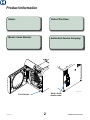
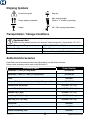
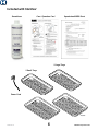
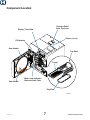
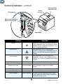
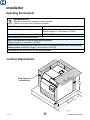
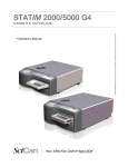
M9 / M9D / M11
Self -Contained Steam Sterilizer
For Models:
M9 (-020 /-021 -022)
M9D (-022)
M11 (-020 / -021 / -022)
Installation
Operation Guide
TP202 Rev. A
003-2707-00 Rev. A (12/9/13)
Style L
Product Information
Dealer :
Date of Purchase:
Model / Serial Number:
Authorized Service Company:
MA616300i
Model / Serial
Number Label
Serial Number
TP202 Rev. A
2
© Midmark Corporation 2013
Table of Contents
Important Information
Printer (optional)
Safety Instructions............................................4
Intended Use....................................................4
Electromagnetic Interference............................4
Safety Symbols.................................................4
Shipping Symbols.............................................5
Transportation / Storage Conditions.................5
Authorized Accessories....................................5
Included with Sterilizer......................................6
Component Location.........................................7
Controls and Indicators.....................................8
Sterilization Monitoring Guidelines.................10
Operating the Printer......................................35
Power-Up Message........................................35
Printer Tape Description.................................35
Example of Typical Printout
of a Program Cycle.......................................36
Cartridge Ribbon Replacement......................37
Paper Roll:
Removal......................................................37
Installation...................................................38
External Condensing Tank (optional)
Using the External Condensing Tank..............39
Installation
Operating Environment................................... 11
Location Requirements................................... 11
Electrical Requirements..................................12
Connecting the Power Cord............................12
Troubleshooting
Troubleshooting Chart.....................................40
Informational Messages..................................41
Error Messages..............................................41
Calling for Service...........................................43
Operation
Before Operating the Sterilizer.......................14
Filling the Reservoir........................................14
Qualification Testing........................................15
Guidelines for Loading....................................15
Cycle Parameters...........................................19
Cycle Operation..............................................20
Post Sterilization Processing..........................23
Unloading Hot Trays and Cassettes...............24
Programmable Cycle Buttons.........................26
Specifications / Compliance
Specifications Chart:
M9...............................................................44
M11.............................................................45
Warranty Information
Scope of Warranty..........................................46
Maintenance
Maintenance Messages..................................28
Daily Maintenance..........................................29
Weekly Maintenance.......................................30
Monthly Maintenance......................................32
Extended Use Maintenance............................32
TP202 Rev. A
3
© Midmark Corporation 2013
Important Information
Safety Instructions
The primary concern of Midmark is that this equipment is operated and maintained with the safety of the
patient and staff in mind. To assure safe and reliable operation:
• Read and understand this manual before attempting to install or operate the sterilizer.
• Assure that the appropriate personnel are informed on the contents of this manual.
(This is the responsibility of the purchaser).
• Assure that this manual is located near the sterilizer, or if possible, permanently affixed
to the sterilizer.
Intended Use
The M9 / M11 Ultraclave or M9D Autoclave can be used in medical and dental offices, hospitals, clinics,
nursing homes, laboratories, and other facilities to sterilize heat and moisture stable reusable items (including dental handpieces) that are compatible with steam sterilization. Refer to ‘Loading Trays’ and ‘Standard
Cycle Parameters’ later in this manual for detailed information.
Electromagnetic Interference
This sterilizer is designed and built to minimize electromagnetic interference with other devices. However, if
interference is noticed between another device and this product:
•
•
•
•
Remove interfering device from room
Plug sterilizer into isolated circuit
Increase separation between sterilizer and interfering device
Contact Midmark if interference persists
Safety Symbols
danger
Indicates an imminently hazardous situation which will result in serious
or fatal injury. This symbol is used only in the most extreme conditions.
warning
Indicates a potentially hazardous situation which could result in serious injury.
Indicates a potentially hazardous situation which may result in minor or moderate injury.
It may also be used to alert against unsafe practices
Indicates a potentially hazardous situation which could result in equipment damage.
TP202 Rev. A
Caution
Equipment Alert
4
© Midmark Corporation 2013
Shipping Symbols
Consult user guide
Keep dry
Proper shipping orientation
Max. stacking height
(Refer to “n” number on package)
140 F
Fragile
60 C
Min. / Max. storage temperature
-22 F
-30 C
Transportation / Storage Conditions
Equipment Alert
Water must be drained from the unit’s reservoir before transporting / storing below +32° (0°C).
Ambient Temperature Range:
-22°F to 140°F (-30°C to +60°C)
Relative Humidity:
10% to 90% (non-condensing)
Atmospheric Pressure:
7.2 psia to 15.4 psia (49.6 kPa to 106.4 kPa)
Authorized Accessories
Listed below are the accessories which are authorized for use with these sterilizers.
Unless noted, accessory can be used on the M9 and M11.
Accessory Name
Order Number
Speedclean, 1 (16oz. [.47 liter]) bottle
002-0396-00
Speedclean, 1 case (12 - 16oz. [.47 liter]) bottles
002-0396-05
Printer
9A259001
Printer refill kit (includes 1 printer cartridge & 1 paper roll)
002-0371-00
Cassette Rack (Horizontal)
9A215001 (M11 only)
Cassette Rack (Vertical)
9A215002 (M11 only)
Cassette Tray (Large)
9A306001 (M11 only)
Deep Tray (2 1/2” [6.4 cm])
9A224001 (M9 only)
Deep Tray (2 1/2” [6.4 cm])
9A225001 (M11 only)
Pouch Rack
9A226001
Tray / Cassette Tool
9A307001
External Condensing Tank
9A260001
TP202 Rev. A
5
© Midmark Corporation 2013
Included with Sterilizer
Speedclean
Care / Operation Card
Speedclean MSDS Sheet
2 Large Trays
2 Small Trays
Power Cord
TP202 Rev. A
6
© Midmark Corporation 2013
Component Location
Pressure Relief
Valve Test Lever
Display / Touch Pad
Printer (optional)
Fill Opening
Door Gasket
Tray Rack
Tray(s)
Dam Gasket
Water Level Indicator /
Reservoir Drain Tube
Tray Plate
SA1775i
TP202 Rev. A
7
© Midmark Corporation 2013
Controls & Indicators
The sterilizer controls and indicators are shown in the illustrations on this, and the following page.
The accompanying tables describe the function of each control / indicator.
Control
Display
Function
see illustration Indicates cycle selected, cycle temperature and exposure time
for the selected cycle. During the cycle, display shows messages
describing status of cycle. When cycle enters sterilization mode,
remaining cycle time is displayed as well as temperature and
pressure. Display also shows error message if a malfunction
occurs. Refer to the Troubleshooting section of this manual for a
detailed explanation of Informational / Error Messages.
Unwrapped button
A program cycle designed to process unwrapped instruments at:
270° F (132° C) for 3:00 minutes / 30 minute drying cycle.
Pouches button
A program cycle designed to process instruments in combination
paper / plastic sterilization pouches or wrapped instruments at:
270° F (132° C) for 5 minutes / 30 minute drying cycle.
Packs button
A Program cycle designed to process packs of instruments at:
250° F(121° C) for 30 minutes / 30 minute drying cycle.
Handpieces
button
A program cycle for dental handpieces which runs at:
270° F(132° C) for 6 minutes / 30 minute drying cycle.
Start button
Initiates selected program or, when SELECT CYCLE is displayed,
pressing Start will activate heater for 10 minutes.
Stop button
Terminates selected program or function.
1 or 2 buttons
NOTE: All material
run in these cycles
must be validated
for sterilization by
the user.
TP202 Rev. A
Programmable cycle buttons that allows an operator to create two
different programmed cycles for special applications. Sterilization
time and temperature, along with drying time and venting procedure can be adjusted or changed.
8
© Midmark Corporation 2013
Controls & Indicators - continued
Printer
(optional)
Fill Opening
Pressure Relief
Valve Test Lever
Water Level Indicator &
Reservoir Drain Tube
Door Handle
Control
Function
P button
Programming mode button that allows operator to
change temperature, time, dry time and/or venting
procedure. Used in conjunction with buttons 1 or 2.
(Refer to Programming Mode).
+ (plus) button
Allows temperature, time, or dry time to be
increased or changes Vent to Fast mode when in
location 1 or 2 and the P (programming) mode is
activated.
- (minus) button
Allows temperature, time, or dry time to be
decreased or changes Vent to Slow mode when
in location 1 or 2 and the P (programming) mode is
activated.
Door Handle
refer to illustration For latching / opening door.
Water Level Indicator /
Reservoir Drain Tube
Shows amount of water in reservoir. Tube also
refer to illustration used for drainage of reservoir into suitable
container.
Fill Opening
refer to illustration Access for filling reservoir with distilled water.
Pressure Relief Valve Test Lever refer to illustration Allows operator to check pressure relief valve.
Printer (Optional)
TP202 Rev. A
refer to illustration The printer (optional equipment) can be used to
provide a permanent record of time, temperature,
and pressure during a cycle.
9
© Midmark Corporation 2013
Sterilization Monitoring Guidelines
Note
This information below is provided for reference only. Contact appropriate state/local agencies for
specific sterilization guidelines for your office. Additional information on infection control is available
from the Centers for Disease Control and Prevention (CDC), Organization for Safety and Asepsis
Procedures (OSAP) ), Association for the Advancement of Medical Instrumentation (AAMI), and
Association for Professionals in Infection Control and Epidemiology (APIC).
Physical Monitors
Temperature and pressure measuring devices can help detect sterilizer malfunctions. The sterilizer’s control
system aborts the cycle and displays a message if physical conditions go outside established limits. The
optional printer can be used to create a record of each load’s actual cycle time, temperature, and pressure.
Note
Use only FDA cleared chemical & biological indicators designed for steam sterilization that are
compatible with the particular sterilization cycle temperature and exposure time being monitored.
Use sterility monitors with each sterilization load. If a sterilizing cycle is terminated prematurely,
reprocess instruments to ensure sterility of the load. Follow manufacturer’s instructions for proper
disposal of used indicators.
Chemical Indicators
Chemical indicators are designed to verify that conditions in the sterilizer chamber were adequate to achieve
sterilization. They do not validate that a processed item is sterile. If a chemical indicator shows a failure,
items in that load are considered non-sterile. Potential causes for sterilization failure include: improper
packing, loading, or a sterilizer malfunction. Determine the cause of any sterilization failure, and remedy
the situation before running the next cycle. Only FDA cleared chemical indicators labeled for use with the
nontraditional steam sterilization cycle parameters. e.g. temperature and exposure time, of the M9 / M11
Sterilizers should be used for monitoring the cycles. Follow the chemical indicator’s instructions for proper
storage, use, interpretation, and disposal.
Biological Indicators
Biological indicators are microbiological devices designed to accompany items being sterilized to monitor
adequacy of the sterilization process. If a biological indicator shows a failure, items in that load are
considered non-sterile. Potential causes for sterilization failure include: improper packing, loading, or a
sterilizer malfunction. Determine the cause of any sterilization failure, and remedy the situation before
running the next cycle. Only FDA cleared biological indicators labeled for use with the nontraditional
steam sterilization cycle parameters. e.g. temperature and exposure time, of the M9 / M11 Sterilizers
should be used for monitoring the cycles. Follow the biological indicators instructions for proper storage,
use, interpretation, and disposal.
TP202 Rev. A
10
© Midmark Corporation 2013
Installation
Operating Environment
Equipment Alert
Allow unit to reach room temperature before operating.
Failure to do so may result in damage to sterilizer.
Ambient Temperature Range:
68°F to 104°F (+20°C to +40°C)
Relative Humidity:
< 80% (non-condensing)
(Pollution Degree 2, in accordance to IEC664)
Normal Operating Altitude:
< 9842 ft. (3000 m) above sea level
Device approved for INDOOR USE ONLY.
Device to be operated in a relatively dust-free environment.
(Pollution Degree 2, in accordance to IEC664)
Device should be connected to a power source with over-voltage limits less than 1500 watts from
mains to ground. (Installation Category II in accordance to IEC664)
The M9 and M11 will emit 5000 BTU / HR during operation.
Location Requirements
ts
ar
le
C
en
em
ir
an
u
ce
eq
R
5
(13 "
cm
5" )
cm
)
ve
rh
2
(5 "
cm
)
O
Allow Clearance
on Both Sides
an
g
/S
h
el
f
(13
1
M118" m)
c
(46
Su
pp
ort
Su
rfa
ce
(3
TP202 Rev. A
11
1" )
cm
M95"
1 cm)
(38
1
M1 1"
2 cm)
(53
23 M11
" (5
8
M cm
22 9 )
2" )
" (5
6)
cm
(5
M9 8"
1 cm)
(46
© Midmark Corporation 2013
Installation
Location Requirements continued...
Support Surface
• Material should be water-resistant material. (Ex. laminate, stainless steel, stone, etc.)
• Surface must be level to ensure chamber fills with correct water level.
Improper water level in the chamber could cause a sterilizer malfunction.
• Surface should meet minimum dimensions listed below:
Dimensions
Depth (front to back)
M11 - 21” (53 cm) M9 - 18” (46 cm)
Clearance Requirements
To ensure proper air circulation, and to allow access to the reservoir fill port and drain coupling,
adhere to the minimum clearance requirements listed below. If the sterilizer will be operated
in continuous cycles, locate sterilizer where steam will not damage materials or equipment in
the surrounding area.
Back of Unit - Back Wall.................................. 2” (5 cm)
Front Support Surface - Front Sterilizer......... 1” (3 cm)
Sides of Unit - Side Wall................................. 2” (5 cm)
Distance above Unit for Printer Access........... 5” (13 cm)
Maximum Upper Cabinet Shelf Overhang...... M11 - 18” (46 cm) M9 - 15” (38 cm)
Under Cabinet or Shelf................................... M11 - 23” (58 cm) M9 - 22” (56 cm)
Relocation Requirements for Sterilizer
Disconnect power cord from electrical outlet and allow sterilizer to cool.
Drain water from reservoir or do not tip sterilizer, allowing water to spill.
Electrical Requirements
warning
For 115 VAC models: Use 104 - 127 VAC, 50/60 Hz alternating current only.
For 230 VAC models: Use 207 - 253 VAC, 50/60 Hz alternating current only.
Failure to do so may result in electric shock to personnel and / or damage to sterilizer.
Note
For safety, the unit must be connected to a properly polarized and grounded receptacle. Always use a
power cord with grounding connections that match the receptacles in your location.
115 VAC Unit:
115 VAC, 50/60 Hz, 12 amp
Dedicated Supply Circuit*: 120 VAC, 50/60 Hz, 15 amp
Max. Power Consumption: 1425 Watts
230 VAC Unit:
230 VAC, 50/60 Hz, 6.5 amp
Dedicated Supply Circuit*: 230 VAC, 50/60 Hz, 10 amp
Max. Power Consumption: 1500 Watts
* Power source must have over-voltage limits less than 1500 watts from mains to ground.
(Installation Category II in accordance to IEC664)
TP202 Rev. A
12
© Midmark Corporation 2013
Connecting the Power Cord
warning
Equipment is not suitable for use in the presence of a flammable anesthetic mixture with oxygen, air, or nitrous oxide.
Clarification: Equipment is suitable for use in the presence of oxygen, air, or nitrous oxide.
warning
Check the serial number label on back panel of sterilizer to verify voltage rating for
the unit. Failure to connect sterilizer to an appropriate power supply could result in
damage to the unit, and electrical shock to personnel.
Equipment Alert
For optimal performance, allow sterilizer to reach
room temperature before operating.
To connect the power cord...
A) Plug power cord into receptacle on back of sterilizer.
B) Plug power cord into a properly polarized and grounded receptacle rated for a minimum of 15 amps. A dedicated circuit only used for the sterilizer is recommended.
Note: When power is connected, the messages shown below will appear on the display.
Display:
Voltage Rating
*
* This screen will display the total number of cycles run on the unit,
the model number (M9 or M11), and the software version number.
TP202 Rev. A
13
© Midmark Corporation 2013
Operation
Before Operating the Sterilizer...
warning
Do not use this sterilizer for sterilizing volatile substances or for any purpose other than its intended design. Burns and toxic or explosive conditions could result.
Do not force door handle at any time. Chamber pressure may cause door to open with
extreme force. If door handle does not move freely, allow until to cool and depressurize for
40 minutes before opening door. Failure to adhere could result in serious personal injury.
Do not run the sterilizer without the tray plate in place. If the sterilizer malfunctions, immediately unplug sterilizer, and call for service; do not attempt to repair the sterilizer
yourself. Doing so could result in serious injury.
Caution
Programmable cycles 1 & 2 are provided for those applications requiring sterilization
parameters different than the preset cycles. All material processed in these cycles must
be validated by the user to ensure sterility of the processed load.
Equipment Alert
For optimal performance, allow the sterilizer to reach room temperature before operating.
Filling the Reservoir
Equipment Alert
Use distilled water only!
Failure to comply may result in sterilizer
malfunction and/or premature failure due to excessive
corrosion.
To fill reservoir...
A)
B)
Open door to unit.
Pour distilled water into fill opening until water level reaches the top of the fill level label on the water level indicator tube.
TP202 Rev. A
14
© Midmark Corporation 2013
Qualification Testing
After sterilizer installation, relocation, major repairs, and sterilization process failures qualification testing
using BI challenge test packs or trays should be performed prior to placing the sterilizer in service. If multiple
cycle types are used, e.g. “Pouches” and “Packs” each cycle type should be qualified. The BI challenge test
pack or tray should contain items routinely processed and considered to be the most difficult to
sterilize along with at least one BI and one CI. Additional items should be placed in the chamber along with
the test pack or tray so the chamber is fully loaded (don’t exceed the maximum capacities listed in the tables
under “Guidelines for Loading” in this manual). Three consecutive test runs, for each cycle type tested, with
negative results from the BIs, and appropriate readings from all physical monitors and CIs demonstrating
complete sterilization, provide verification that the sterilizer has been properly installed (or reinstalled after
relocation) or repaired to the manufactures’s specifications and that it will function effectively in the facility in
which it is installed. All items processed during qualification testing should be quarantined until the results of
the BI testing for all three test runs are available.
Guidelines for Loading
Types of Items
Before placing any instrument in the M9 or M11, check with the instrument manufacturer to be sure the
materials are compatible with steam sterilization, and to verify the acceptability of sterilization
parameters. The M9 and M11 are designed to sterilize the following:
•
•
•
•
•
•
TP202 Rev. A
Metal instruments
Rubber / plastic devices (ex. suction cannulas, impression trays, etc.)
Wrapping / bundling materials (ex. CSR wrap, instrument pouches, etc.)
Cassettes
High / low speed handpieces
Surgical instruments (ex. opthalmologic instruments)
Equipment Alert
Do not sterilize items composed of any of the following materials in the M9 or M11.
• Corrosion sensitive metal (ex. carbon steel, iron, etc.)
• Fragile items susceptible to breaking under pressure / high temperature
• Biomedical waste
• Plastics that may break down or produce residue when exposed to steam / high
temperatures.
Examples
Polyethylene, Styrene, Cellulosics, ABS, PVC, Acrylic (Plexiglass™), PPO (Noryl™),
Latex, and Neoprene
15
© Midmark Corporation 2013
Guidelines for Loading - continued
General Guidelines
Caution
Clean and dry instruments thoroughly before placing them into tray. Improper cleaning may result in non-sterile instruments or damage to the unit. Follow instrument manufacturer’s
guidelines and CDC recommendations for handling and cleaning instruments prior to sterilization.
•
•
•
•
Place all containers so that the opening allows steam to enter, and air / condensate to drain
from the container.
Use only M9 and M11 trays in their appropriate sterilizer.
Using other trays could restrict air / steam flow to items.
Sterilize jointed items in an open position.
Handpieces and instruments must be single height loaded (not piled or stacked), to permit proper steam flow and penetration to the items.
Immediate Use Sterilization
The M9 and M11 are capable of Immediate Use sterilization - sterilizing unwrapped instruments for immediate use. Place a towel or absorbant paper on the bottom of the tray before putting unwrapped items in the
tray. Please consider the following when choosing whether or not to sterilize your instruments unwrapped:
•
•
The sterility of unwrapped instruments is compromised upon exposure to a non-sterile
environment. Follow CDC guidelines for using unwrapped, sterilized instruments.
Due to the sensitive nature of some types of surgery (including, but not limited to
ophthalmological), instruments used in such procedures must be wrapped or pouched in
order to reduce their exposure to sterilization process residues. The water reservoir should
also be drained and refilled with fresh distilled water on a daily basis when processing
instruments for these procedures on a routine basis.
Pouching and Wrapping Items
The M9 and M11 are capable of sterilizing pouched or wrapped items to preserve sterility after processing.
•
•
•
•
•
When pouching or wrapping items, use only sterilizer pouches and wraps that have been
cleared by the FDA and labeled for use with the steam sterilization cycle being used. Follow the manufacturer’s instructions for use.
When using cassettes in the M9 / M11, follow the manufacturer’s instructions for use.
Do not wrap items too tightly. Sterilization can be compromised if an item is excessively wrapped.
Pouches should be loosely packed and may overlap, but handpieces and instruments must be single height loaded (not piled or stacked), to permit proper steam flow and penetration to the items.
The preferred orientation of pouches is resting on their edge, best accomplished using the Midmark pouch rack accessory. If using the standard tray, pouches should be placed with paper side down.
TP202 Rev. A
16
© Midmark Corporation 2013
Guidelines for Loading - continued
Packing the Trays
Equipment Alert
Do not use towels or packaging containing chlorine bleach residue. Failure to comply may cause rusting or discoloration of the chamber / trays, and significantly shorten the life of the
sterilizer.
Trays must be used at all times when operating this sterilizer - unless the optional cassette rack kit is
used - otherwise, serious equipment damage could result.
All items must be processed in accordance with Centers for Disease Control and Prevention (CDC),
“Guidelines for Infection Control in Dental Healthcare Settings” - 2003, MMWR; 52 (no. RR-17), and
“Guidelines for Disinfection and Sterilization in Healthcare Facilities” - 2008, which states:
“Items to be sterilized should be arranged to permit free circulation of the sterilizing agent (e.g., steam, chemical vapor, or dry heat); manufacturer’s instructions for loading the sterilizer should be followed.”
• All items to be sterilized should be arranged to permit free circulation of the steam. • All items must fit in M9 / M11 tray.
• Loaded tray must slide into chamber opening without scraping.
• Instruments must not touch one another.
• Pouches may overlap slightly, but items must not be layered.
TP202 Rev. A
17
© Midmark Corporation 2013
Guidelines for Loading - continued
Load Size
Refer to the charts below for maximum sterilization loads. If a load surpasses these limits, we recommend
dividing the load and running multiple cycles. Listed below are the maximum recommended loads for
each tray and total loads:
warning
Do not overload the chamber. Adequate space is required around items in trays for steam circulation and drying. Failure to allow adequate space will compromise
sterilization and drying. Do not run the sterilizer without the tray plate in place.
M9 (maximum capacities)
Load Type
M9 Large Deep Tray
M9 Small Tray
M9 Sterilizer Total
Solid Items
42 instruments 2.4 lbs. (1089 grams) or
28 instruments 1.6 lbs. (726 grams) or
140 instruments 8.0 lbs. (3629 grams) or
Handpieces
9 in a rack or
9 in a rack or
9 handpieces in a rack and
75 instruments or
Packs*
66 in3 (< 1 in. thick)
1082 cm3 (< 2.5 cm thick)
48 in3 (< 1 in. thick)
787 cm3 (< 2.5 cm thick)
228 in3 (< 1 in. thick)
3736 cm3 (< 2.5 cm thick)
M11 (maximum capacities)
Load Type
M11 Large Deep Tray
M11 Small Tray
M11 Sterilizer Total
Solid Items
45 instruments 2.7 lbs., (1225 grams) or
30 instruments 1.8 lbs., (816 grams) or
150 instruments 9.0 lbs., (4082 grams) or
Handpieces
9 in a rack or
9 in a rack or
9 handpieces in a rack and
75 instruments or
Packs*
270 in3 (< 2 in. thick)
4425 cm3 (< 5 cm thick)
195 in3 (< 2 in. thick)
3195 cm3 (< 5 cm thick)
930 in3 (< 2 in. thick)
15240 cm3 (< 5 cm thick)
*Allow a minimum of 1/4” (6.4 mm) space between each pack, and also from the chamber wall.
TP202 Rev. A
18
© Midmark Corporation 2013
Cycle Parameters
Program
Temp / Pressure /
Time
(minimums)
Items to be Sterilized
(Always consult the item manufacturer’s
recommendations for sterilization.)
270°F (132°C)
27.1 psi (186 kPa)
Sterilize: 3 min.
Dry: 30 min.*
• Instruments loose on a tray.
• Open glass or metal canisters.
• Tubing not used in surgical procedures.
• Loose items manufacturers recommend for exposure at
270°F (132°C).
Note: The sterility of unwrapped items is compromised on
exposure to a non-sterile environment.
270°F (132°C)
27.1 psi (186 kPa)
Sterilize: 5 min.
Dry: 30 min.*
• Pouched or loosely wrapped instruments.
• Multiple layers of instruments separated by fabric.
• Wrapped trays of loose instruments.
• Wrapped cassettes.
• Tubing not used in surgical procedures.
• Wrapped items manufactures recommend for exposure
at 270°F (132°C)
• Textiles and surgical packs wrapped for sterilization.
• Items, except liquids, manufacturers recommend for
exposure at 250°F (121°C) for 30 minutes.
Packs
250°F (121°C)
15 psi (104 kPa)
Sterilize: 30 min.
Dry: 30 min.*
• Dental handpieces (wrapped or unwrapped)
Note: Verify acceptability of sterilization parameters with
handpiece manufacturer.
Handpieces
270°F (132°C)
27.1 psi (186 kPa)
Sterilize: 6 min.
Dry: 30 min.*
230°F (110°C) to
275°F (135°C)
• Items appropriate for user’s defined parameters.
Unwrapped
Pouches
6 psi (41 kPa) to
31 psi (214 kPa)
Programmable
User Defined
Sterilize: 3 min. to
90 minutes
Caution
All material run in these cycles must be validated
by the user.
These programmable functions allow you to set different
time and temperature parameters. It is important to properly
coordinate sterilization temperature with cycle time. Permitted
temperature range for proper sterilization is 250° to 275°F
(121° to 135°C). Temperatures below 250°F (121°C) should
only be used for disinfection. Items with long small diameter
tubular canals (complex lumens), e. g. dental handpieces,
scopes, etc. should not be processed for less than 6 minutes
at 270°F (132°C).
* Dry time can be changed from 0 to 60 minutes. Refer to Cycle Operation.
TP202 Rev. A
19
© Midmark Corporation 2013
Cycle Operation
Refer to the following steps for a detailed description of cycle operation:
Equipment Alert
The sterilizer will not operate unless the door is closed and latched properly.
Step 1:
Close and latch the door.
A) Lift the door handle, then push the door closed.
B) While pushing in on the door, slide the door handle down to engage the latch.
Cycle Buttons
(Programmable)
Cycle Buttons
(Pre-set)
Note
Pressing the Start button when ‘SELECT CYCLE’ is
displayed, at beginning or end of a cycle, activates
the heater for 10 minutes. The display flashes
‘ADDITIONAL HEAT’. This allows the operator to
preheat the chamber before starting a cycle or to
add additional time to the Dry mode at the end of a
cycle. Pressing the Stop button will end the
‘ADDITIONAL HEAT’ time.
Equipment Alert
Using an incorrect sterilization program could result in non-sterile goods and may
damage instruments. Consult instrument manufacturer for specific sterilization instructions.
Step 2:
Select the desired cycle.
A) Press the appropriate cycle button on the display panel.
(Refer to “Cycle Parameters” chart for time / temperature specifications).
TP202 Rev. A
20
© Midmark Corporation 2013
Cycle Operation - continued
After the cycle button is pressed, the parameters for that cycle will appear on the display.
Note
On units using the metric display, °F will display as °C and PSI will display as KPA.
Pressing
enables operator to change DRY time from 0 to 60 minutes in 1 minute
increments on a pre-set cycle.
Pressing
decreases time. Pressing
increases time.
MA596700i
Start
Stop
MA596700i
WARNING
STOP button may be pressed at any time to stop or interrupt a cycle. Goods must not be considered sterile if this occurs
before the Dry Cycle. Sterilizer will return to SELECT CYCLE mode.
Step 3: Press ‘Start’ button to initiate cycle.
You will hear a “beep” for two seconds, indicating the cycle has started.
TP202 Rev. A
21
© Midmark Corporation 2013
Cycle Operation - continued
After the ‘Start’ button is pressed, the stage / status of the current cycle will appear on the display.
The chart below illustrates the display messages that will appear during each stage of the cycle.
MA596700i
Stage of Cycle
Filling
Description
Display
Chamber begins filling with water.
When water reaches the proper level...
Heating
Display changes as temperature and
pressure in chamber changes.
(Metric units may be displayed if desired).
Sterilizing
Sterilizing begins when correct
temperature / pressure is reached.
Time remaining in cycle counts down
while current temperature / pressure in
chamber is continuously updated.
Ready to Vent
‘READY TO VENT’ is displayed when
10 seconds remain in sterilization cycle.
Fast Vent
When time runs out in sterilizing mode,
the vent valve opens. Steam / water are
released back into the reservoir.
The display changes as temperature and
pressure in chamber changes.
Caution
Keep clear when M9/M11 door is ready to open!
Failure to do so could result in severe burns from steam being released.
Door To Open
(automatic)
Pertains only to
M9/M11 UltraClave™
An audible signal is emitted to indicate
that the door is about to open.
When pressure in chamber reaches zero,
the door actuates to partially open (drying
mode) position.
This chart continues on the following page...
TP202 Rev. A
22
© Midmark Corporation 2013
Cycle Operation - continued
Stage of Cycle
Description
Manual Door Open
An Audible signal is emitted when pressure inside chambers reaches zero to
indicate Operator to open door. The door
should be opened to the first stop (drying mode) position. The audible signal
will continue to repeat every minute until
either the door is opened to the DRY (partially opened) position, or by pressing the
STOP button, aborting the DRY cycle.
Pertains only to
M9D AutoClave
Drying
Display
Time of Dry Cycle is counted down. If
desired, the Dry Cycle can be aborted by
pressing the STOP button.
When Drying time reaches 0:00...
Cycle Complete
An audible signal is emitted for 10
seconds.
Caution
The processed load and inner surfaces will be hot. Avoid contact with hot surfaces.
Failure to do so could result in serious burns.
Step 4: Remove processed load from the chamber.
A) Refer to “Unloading Hot Trays / Cassettes” later in this manual.
B) Sterilizer is now ready for another cycle.
Post-Sterilization Processing
After sterilization is complete, all items must be handled in accordance with accepted and documented
standards, such as the Centers for Disease Control and Prevention (CDC) documents, “Guidelines for
Infection Control in Dental Healthcare Settings” - 2003, MMWR; 52 (no. RR-17), and “Guidelines for
Disinfection and Sterilization in Healthcare Facilities” - 2008, as well as any local requirements that may
apply.
Qualified personnel responsible for infection control should prepare a protocol for handling sterilized items.
This protocol should be followed by all personnel responsible for handling sterilized items, and should
include the basics:
• Unwrapped sterilization is not recommended for critical or implantable items.
• Unwrapped items should be transported immediately and aseptically from sterilizer to point of use.
• Allow items to dry before handling or storage.
• Wrapped items may be stored before use.
• The storage area should be a closed or covered space, away from environmental contaminates or wetness.
TP202 Rev. A
23
© Midmark Corporation 2013
Unloading Hot Trays / Cassettes
(Using the Optional Tray / Cassette Tool)
Caution
Only use the 9A307001 Tray / Cassette tool with Midmark manufactured trays.
Trays / cassettes may be HOT - use care when removing or transporting.
Hold the tray level and slightly elevated to prevent it from shifting and becoming dislodged.
Failure to comply may result in personal injury due to burns.
Step 1: Assemble the tray / cassette tool.
A) Slide the proper plate* into the handle as shown.
Note: There are three plates included. Each plate is designed for
a specific purpose. (M9 trays, M11 trays, cassettes).
TP202 Rev. A
24
© Midmark Corporation 2013
Unloading Hot Trays / Cassettes - continued
(Using the Optional Tray / Cassette Tool)
To remove M9 / M11 trays...
A) Hook the top, saw-toothed tab of tool to top center tray lip.
B) Rotate tool downward until the tool plate is completely under tray.
C) Check to ensure tray is being held securely and then remove tray from chamber.
Caution
When removing the cassette, hold the cassette tool so the end of the cassette
is slightly elevated and use care to prevent it from sliding off the casette tool.
To remove cassettes...
A)
B)
C)
Hook the top, saw-toothed tab of tool to top center of cassette.
Rotate tool downward until the tool plate is completely under cassette.
Check to ensure cassette is being held securely and then remove
cassette from chamber.
Note: Cassette tool can handle cassettes up to 1 1/2” (3.8 cm) thick.
TP202 Rev. A
25
© Midmark Corporation 2013
Programmable Cycle Buttons
Cycle buttons
can be used for custom applications that are not covered by standard cycle
programs. Once a custom program has been stored, it can be used just by pushing the or button.
Use the instructions in the chart below to set time / temperature parameters for these buttons.
(If you wish to change the settings, these buttons may be reprogrammed at any time).
MA596700i
NOTE:
Pressing the STOP button during this procedure will abort the changes, and revert to the original settings.
Action
Press desired
button
Press
Description
Display
This selects the button that will be
programmed.
This brings up the sterilization
temperature programing display.
Caution
Sterilization temperature can be adjusted from a minimum of 230°F (110°C) to a
maximum of 275°F (135°C). Permitted temperature range for proper sterilization
is 250° to 275°F (121° to 135°C).
Temperatures set below 250°F (121°C) should not be used for sterilization,
unless otherwise required by the device manufacturer. Temperatures below
250°F (121°C) are provided for disinfection only.
Adjust Sterilization
Temperature
The “+” and “-” buttons adjust the
temperature by 1° increments.
When the desired temperature appears
on the display...
This chart continues on the following page...
TP202 Rev. A
26
© Midmark Corporation 2013
Programmable Cycle Buttons - continued
NOTE:
Pressing the STOP button during this procedure will abort the changes, and revert to the original settings.
Action
Press
Description
Display
To store the temperature. This brings up
the sterilization time programing display
showing the current value.
Caution
Sterilization time can be adjusted from a minimum of 3 minutes to a maximum
of 90 minutes. It is important to properly coordinate the cycle time with the
sterilization temperature.
Adjust Sterilization
Time
The “+” and “-” buttons adjust the
time by 1 minute increments.
When the desired time appears on the
display...
Press
Adjust Vent Speed
To store the sterilization time. This brings
up the vent speed programing display and
the current value.
In FAST vent, the valve fully opens and
vents the chamber.
In SLOW vent, the valve opens for a
fraction of a second (once per minute)
to slowly vent the chamber.
Pressing “+” sets it to: FAST
Pressing “-” sets it to: SLOW
When the desired setting appears on the
display...
Press
To store the setting and bring up the dry
time programing display and the current
value.
This chart continues on the following page...
TP202 Rev. A
27
© Midmark Corporation 2013
Programmable Cycle Buttons - continued
NOTE:
Pressing the STOP button during this procedure will abort the changes, and revert to the original settings.
Action
Adjust Dry Time
Description
Display
Dry time can be adjusted from 0 to 60
minutes.
The “+” and “-” buttons adjust the
time by 1 minute increments.
When the desired time appears on the
display...
Press
To store the setting and complete the programming process. The display will show
the new cycle parameters.
Note
The programmed settings are retained under Program # button <1> or <2>.
Even if power is interrupted, or the unit is unplugged the setting will be retained.
Caution
All materials processed using these cycles must be validated by the user.
Failure to do so could result in incomplete sterilization.
Maintenance
Maintenance Messages
To assure proper operation and maximum sterilizer life, carefully follow all recommendations for periodic
maintenance. Recommended maintenance is easy to do and takes very little time.
One of the MOST important steps you can take to prevent problems with your sterilizer is to ensure that
ONLY distilled water - NOT TAP WATER - is used in the sterilizer. Since the sterilizer operates with high
water temperatures, any minerals dissolved in the water will form mineral deposits. This can prevent valves
from opening or closing properly and can also lead to corrosion in the chamber and tubing.
Maintenance reminders will be displayed on the screen at the appropriate intervals to assist the operator.
These reminders are removed from the display screen once a cycle is started.
The user is responsible for establishing a periodic maintenance procedure to assure correct operation of
equipment and reliable sterilization of loads. Contact your local Midmark distributor or service representative
to develop a program for planned maintenance.
TP202 Rev. A
28
© Midmark Corporation 2013
Daily Maintenance
Equipment Alert
If the sterilizer is used frequently to process dental handpieces that have been lubricated or dipped in dental milks, drain the water from the reservoir daily.
Refill the reservoir with distilled water.
• Clean External Surfaces
A) Wash the exterior of the sterilizer each day according to your facility’s procedure for clinical contact B)
C)
D)
surfaces, noting the following: (Use only quaternary disinfectants to disinfect unit. Staining, pitting, discoloration, or softening could occur if phenolic, iodophor, or glutaraldehyde-based disinfectant is used on plastic surfaces of the unit. Also, use of alcohol or aerosol spray cleaner / disinfectant containing substantial amounts of alcohol in the formula can damage the faceplate).
Wring excess solution from the cloth.
Using soft cloth, wipe all external surfaces.
Do not rinse or dry external surfaces. Allow germicidal solution to air dry.
• Clean sterilizer door / dam gaskets.
Caution
To prevent burns, allow unit to cool before
cleaning gaskets and mating surfaces.
A)
Examine gaskets for possible damage. B) Clean gaskets and mating surfaces with a damp cloth.
Door Gasket
Dam Gasket
TP202 Rev. A
29
© Midmark Corporation 2013
Weekly Maintenance
Equipment Alert
Failure to change water may result in sterilizer malfunction.
Do not use bleaching agents or any abrasive materials / substances in chamber
(i.e. bleach, steel wool, wire brush, scouring powder, etc.).
Failure to comply may result in damage to the chamber and/or other components.
Note
Every seven days, the autoclave will automatically display the PERFORM WEEKLY MAINTENANCE
message. If power is disconnected, the cycle of weekly messages will be reset.
• Clean Chamber / Trays (including Rack and Plate)
A) Disconnect the upper portion of the reservoir drain tube from the panel clips, bend it downward, B)
C)
D)
and drain the reservoir water into a suitable container, e.g. a bucket, and dispose of the water.
Remove the trays, tray rack, and tray plate from the sterilizer.
(Refer to the following page for instructions on removing / installing the tray rack and tray plate).
Wash trays, rack, plate, and inside of chamber with mild soap or Speed-Clean and distilled water. Refill reservoir with distilled water.
Tray Rack
Trays
TP202 Rev. A
Tray Plate
30
© Midmark Corporation 2013
Weekly Maintenance - continued
WARNING
Allow unit to cool before removing or installing tray rack and plate.
Handle metal tray rack carefully to avoid injury. Do not run sterilizer without
tray plate in place.
To remove tray rack / plate...
A) Remove trays.
B) Using a screwdriver, pry plate up while pulling tray rack / plate out of chamber.
Tray Rack
Tray Plate
(Angled end must face back of chamber)
Equipment Alert
Install tray rack / plate with angled end of plate toward the back of the chamber.
Do not allow plate to contact the water level sensor.
To install tray rack / plate...
A) Insert the tray rack into the tray plate.
B) Place back of tray plate in chamber.
C) Press down on tray rack, while sliding into chamber.
TP202 Rev. A
31
© Midmark Corporation 2013
Monthly Maintenance
warning
Do not process instruments while flushing system.
Note
Every 28 days, the sterilizer will automatically display the PERFORM MONTHLY MAINTENANCE
message. This is a more thorough cleaning of the unit and involves multiple steps. If power is
disconnected, the cycle of monthly messages will be reset.
• Clean Chamber / Plumbing
A) With a cooled chamber, drain the sterilizer’s reservoir and refill with clean, distilled water.
Add one ounce of SpeedClean sterilizer cleaner directly to the bottom of chamber.
B) Run one Pouches cycle.
C)Press Stop button when Dry Cycle begins.
(It is not necessary for the dry cycle to run during this maintenance.)
D) Drain reservoir and refill a second time with clean, distilled water for the rinse cycle.
E) Rinse by running one Unwrapped cycle
begins.
, but push the “Stop” button when the drying cycle F) Drain and refill reservoir with clean distilled water, then allow sterilizer to cool.
G)
Remove trays and tray rack. Wipe off with a damp cloth.
H)
Remove and clean filters. The filters are intended to prevent debris from causing valve failures. Between regular monthly cleanings if the fill or vent times become too long or items will not dry the filters should be cleaned.
I)
Refer to the illustration for location of filter screens.
Air Filter Screen
Steam Temperature Probe
Fill / Vent
Filter Screen
SpeedClean
sterilizer cleaner
Level Sensor Probe
Heating Element
MA8195-1i
TP202 Rev. A
32
© Midmark Corporation 2013
Monthly Maintenance - continued
J) Grasp filter and gently pull away from chamber wall while twisting slightly.
(If necessary, pliers may be used to remove filters)
K) Clean filters with SpeedClean and distilled water. A small stiff bristled brush or
ultrasonic cleaner may be helpful. Rinse filters with distilled water.
(Note: Replace filter(s) if debris cannot be remvoved by cleaning).
Equipment Alert
Use care when wiping the inside of the chamber. Failure to comply may result in
damage to the heating element, steam temperature probe, and/or level sensor probe.
L) Wipe out the inside of chamber.
Equipment Alert
Do not operate sterilizer without filters in place.
M)
Install filters. (Press inward, toward chamber wall while twisting slightly).
N) Install tray plate, rack, and trays.
• Remove / Clean Door & Dam Gaskets
A) Remove door and dam gaskets from chamber door,
Replace gaskets if damage is apparent.
D) Press gasket ring into the channel in the
distilled water, and a soft brush.
C) Inspect gaskets for damage / shrinking / swelling.
then remove the gasket ring from the door gasket.
B) Clean gaskets and ring with SpeedClean,
door gasket and reinstall the gasket in the door.
E) Install dam gasket.
TP202 Rev. A
33
© Midmark Corporation 2013
Monthly Maintenance - continued
• Check Pressure Relief Valve (must be checked each month to assure it functions properly)
A)Press Unwrapped button
B)Press Start button
Caution
During the pressure relief valve check, steam will be vented from under the sterilizer. To keep from being burned, place a steam barrier (a rolled up towel) around the bottom of the sterilizer.
C)
Wait until pressure in chamber
reaches 20 PSI (138 kPa).
MA596700i
D) Pull upward firmly on the pressure relief lever for approximately 3 seconds, then release. (Steam should discharge freely from beneath rear of unit when lever is pulled.
If the valve does not close completely when lever is released,
Pressure Relief
pull lever again and release quickly so that it snaps closed.
Lever
Repeat this until valve seats properly).
E)Press Stop button
(This aborts the cycle to prevent overheating).
Equipment Alert
If excessive force is required to open the pressure relief valve, or if the valve will
not reseat properly, the valve must be replaced.
(Refer to “Calling for Service” in this manual).
MA601301i
Extended Use Maintenance
The M9 and M11 are designed and tested to provide exceptional reliability throughout their
service life. However, like all electro-mechanical devices they are subject to wear and degradation with use.
To ensure the integrity, performance, and safety of all major components it is the responsibility of the user to
have the sterilizer performance / operation verified by a Midmark Authorized Service Provider at least every
10 years or 10,000 cycles, which ever comes first. After 10 years or 10,000 cycles of use, an annual
inspection by a Midmark Authorized Service Provider is recommended.
TP202 Rev. A
34
© Midmark Corporation 2013
Printer (Optional)
Operating the Printer
When the sterilizer is plugged in, the printer is automatically powered up and initialized.
No user intervention or setup is required.
Power-Up Message
When the printer successfully initializes after the sterilizer is powered up, it prints the word “READY” to
assure the operator that its built in microprocessor is working properly and the sterilization cycles will be
recorded by the printer.
Printer Tape Description
The printer will print the following information for each program cycle:
• Cycle Number
• Identification: a line is printed so the sterilizer I.D. can be recorded on the printer tape
• Operator: a line is printed so the operator’s signature can be recorded on the printer tape.
• Date: lines are printed for the month, day, year, hour, and minute so the date and time can be
recorded by the operator on the printer tape.
• “BEGIN selected CYCLE”: to indicated the beginning of the cycle selected by the operator.
• Summary of selected cycle set points.
Once the cycle starts, the printer will print the words “FILLING CHAMBER” to show that the sterilizer is filing
with water.
Once the sterilizer begins the Heating Phase of the sterilization cycle, the word “HEATING” is printed and
the printer will print the chamber temperature, pressure, and elapsed time in 30 sec. increments until the
heating phase is completed.
When the sterilizer enters the sterilization phase, the word “STERILIZING” is printed and the printer will print
the chamber temperature, pressure, and elapsed time in 30 sec. increments until the sterilization phase is
completed.
When the sterilizer has completed the sterilization phase of the program cycle, the printer will print the words
“VENTING CHAMBER” to show that the steam pressure is being exhausted from the chamber.
When the sterilizer enters the drying phase, the word “DRYING” is printed and the printer will print the
elapsed time in 5 minute increments starting with 0:00 and the words “DRYING START”. The printer
continues to print the elapsed time in 5 minute increments until the drying phase is completed. The final
record for the drying phase will include the words “DRYING COMPLETE”. In the event the drying time is
programmed to a time that isn’t divisible by 5, the final printed record for the drying phase will reflect the
actual programmed drying time in 1 minute increments, e.g. a programmed dry time of 12 minutes will have
5,10,and 12 minutes printed on the printer tape.
When the sterilizer has completed the drying phase of the sterilization cycle, the printer will print a summary
of the sterilization cycle with the duration of each phase of the cycle and the Total Cycle Time. Following the
summary the printer will print “CYCLE COMPLETE”.
[NOTE: If drying cycle is aborted, “DRYING COMPLETE” and “CYCLE COMPLETE” will not print].
TP202 Rev. A
35
© Midmark Corporation 2013
Example of Typical Printout of a Program Cycle
Total # of cycles
run on unit
Midmark M9 - v1.0.3
Total Cycles: 10
Line provided for
sterilizer identification
--------------------Sterilizer ID
Space provided for
recording date & time
Line provided for
operator signature
--------------------Operator
- - / -- / ---- --: --
mm / dd / yyyy
hh : mm
Selected Cycle
BEGIN UNWRAPPED CYCLE
Sterilization temperature,
time, and dry time settings
Temp:
270
Time:
3
Degrees F
Minutes
Dry:
30
Minutes
FILLING CHAMBER
HEATING
During Heat-Up phase, the
printer records chamber
temperature & pressure in
30-second increments
mm:ss
Degrees
0:00
233.8 F
0.0
0:30
231.3 F
1.9
2:30
265.7 F
25.0
3:00
271.3 F
28.8
Indicates Filling
phase initiated
PSI
STERILIZING
During Sterilization phase,
the printer records chamber
temperature & pressure in
30-second increments
Indicates Venting
phase initiated
mm:ss
Degrees
PSI
0:00
271.8 F
28.9
0:30
272.4
29.5
2:30
272.7
29.3
3:00
272.6
29.3
Min
271.8 F
28.7
Max
273.2
29.9
Summary of
Sterilization phase
VENTING CHAMBER
DRYING
MM:SS
During Drying phase,
the printer records time in
5-minute increments
0:00
25:00
30:00
These lines will show the
total dry time completed
Drying Start
5:00
Drying Complete
FILLING:
3:22
HEATING:
8:54
STERILIZING:
3:00
VENTING:
2:16
DRYING:
30:00
TOTAL CYCLE
00:47:32
These lines will not print
if Dry Cycle is aborted
before it completes
Cycle summary
CYCLE COMPETE
TP202 Rev. A
36
© Midmark Corporation 2013
Cartridge Ribbon Replacement
Note
If the printed material is difficult to read and you suspect a dried out ribbon is the cause of the problem,
advance to a properly inked portion of the ribbon by pressing the “PAPER FEED” button for three
seconds. If this procedure does not correct the problem, replace the cartridge ribbon.
To replace the cartridge ribbon...
A)
B)
C)
D)
E)
F)
G)
Remove printer assembly from top cover.
Remove the printer cover. (Bend the housing out slightly to release tabs).
Push down on the side of the cartridge marked “Eject”, then remove cartridge.
Install the new cartridge. Be sure the ribbon is inserted in front of the paper,
and flat against the paper.
Press cartridge down until it snaps into place.
Turn the cartridge knob clockwise until ribbon is tight.
Install printer cover / position printer on sterilizer.
Tab
Cartridge Knob
T
EC
EJ
Housing
Paper Roll Removal
Equipment Alert
Be sure to pull the paper out of the top of printer. Pulling from the back will damage the printer.
Before removing the paper roll. advance the paper about 1” (2.5 cm) by pressing down and holding the
“PAPER FEED” button. Lift the paper roll away from the printer housing, and with scissors, cut the paper roll
feeding to the printer. Try to make the cut as straight as possible to facilitate the next reloading of the paper.
Now, pull the remaining paper through the printer mechanism.
TP202 Rev. A
37
© Midmark Corporation 2013
Paper Roll Installation
Equipment Alert
Using paper rolls larger than 1.97” (50 mm) in diameter, may cause the paper feed mechanism to slip and / or damage the printer.
To install the paper roll...
A)
B)
C)
D)
E)
F)
G)
H)
I)
J)
Turn printer onto its back.
Insert spindle into new paper roll.
Unroll 2” to 3” (5 to 7.5 cm) of paper.
If necessary, cut a straight edge on the paper to feed into the printer slot.
Feed approx. 1/4” (6.4 mm) of paper into the printer slot.
While holding paper in place, press/hold “PAPER FEED” button until
1” (2.5 cm) paper comes thru slot in printer cover, then release button*.
Pull 2” to 3” (5 to 7.5 cm) of paper thru printer cover.
Insert paper roll / spindle into slots of spindle holder as shown.
Turn the paper roll to remove slack in the paper feeding to the printer.
Install the printer assembly back into the printer cavity.
*Note:If necessary, remove the printer cover and manually feed the paper thru the slot in the cover.
Paper Feed Button
Printer Slot
Printer Cover
EJE
Spindle
CT
MA46500-1i
TP202 Rev. A
38
© Midmark Corporation 2013
External Condensing Tank (Optional)
Using the External Condensing Tank
Equipment Alert
Do not operate the sterilizer with the external condensing tank completely empty.
The water level must remain between the Min. / Max. lines shown on the tank label.
Failure to comply may result in damage to the tank.
During the Vent mode, steam / heated water will be released into the external condensing tank. When the
water level in the tank reaches the Max. line on the tank label, it must be emptied.
Refill the tank with water to the Min. line before operating the sterilizer.
To empty the external condensing tank...
A) Remove the cap / coil assembly from the condensing tank.
B) Empty the contents of the tank into drain or bucket.
Before the next cycle...
A) Pour water into the condensing tank until it reaches the Min. line.
B) Install the cap / coil assembly onto the tank.
Max.
Min.
TP202 Rev. A
39
© Midmark Corporation 2013
Troubleshooting
Troubleshooting Chart
Use the following chart to assist in correcting minor problems with the sterilizer.
Problem
Sterilizer does not
operate (no display).
Possible Cause
Solution
Sterilizer power cord came loose from
supply outlet or back of sterilizer.
Assure Sterilizer power cord is plugged into
outlet and sterilizer.
No power at Sterilizer supply outlet.
Check circuit breaker for supply outlet. If
problem recurs, unplug unit power cord and
contact an authorized service technician.
(see “Calling for Service”).
Fuse open on main P.C. Board.
Unplug unit power cord and contact an
authorized service technician
(see “Calling for Service”).
Steam escaping
from pressure relief
valve.
Pressure relief valve not properly seated.
Reseat pressure relief valve
(see “Monthly Maintenance”).
Sterilization
failure evidence
from process
monitor (chemical
indicator, biological
indicator, etc.).
Sterilization conditions were not present
at location of the indicator.
Reload sterilizer in accordance with guidelines
for loading the M9 or M11. If problems recurs,
unplug unit power cord and contact an authorized service technician
(see “Calling for Service”).
Indicator is out-of-date, is inappropriate
for sterilization cycle. or has otherwise
malfunctioned.
Use an indicator, appropriate for the load and
cycle selected, that has been stored properly.
Contact the indicator manufacturer for additional
information on proper selection, use, storage,
and potential misapplication or malfunction.
Door gasket leaks.
Door gasket is damaged or dirty.
Clean or replace door gasket
(see “Weekly Maintenance”).
Items are not dry at
end of Dry Cycle.
Sterilizer is improperly loaded.
Reload sterilizer in accordance with guidelines
for loading the M9 or M11.
If problems recurs, unplug unit power cord and
contact an authorized service technician
(see calling for service).
Filter screen(s) clogged. (Check fill / Vent
and Air Valve filter screens)
Clean or replace filter screen(s).
(see “Non-Scheduled Maintenance”)
Printer cable is not connected properly.
Ensure that printer cable is connected to printer
and PC board properly.
Software malfunction.
Unplug sterilizer power cord, wait 15 seconds,
and then plug sterilizer power cord back in.
Printer is out of paper.
Insert a new paper roll (see inserting the paper
roll under printer installation and operation)
Cartridge ribbon is dried out.
(see “Cartridge Ribbon Replacement”)
Printer not printing.
TP202 Rev. A
40
© Midmark Corporation 2013
Informational Messages
The chart below lists the informational messages that may appear during operation.
Message
Possible Cause
Solution
INTIALIZING SYSTEM
Unit power cord was just plugged
in - standard informational
message.
Normal operation will occur after a
4 second pause.
TOTAL CYCLES
XXX M9*, VX.X.X
(*will display model
number, M9, M11)
Unit power cord was just plugged
in - standard informational
message.
Normal operation will occur after this
message.
PERFORM WEEKLY
MAINTENANCE
This message is displayed every
7, 14, and 21 days after the unit
is plugged into a power source to
prompt the operator to preform
weekly maintenance described in
this manuals
Preform weekly maintenance.
The message will automatically clear
after the next cycle is completed.
PERFORM MONTHLY
MAINTENANCE
This message is displaced every
28 days to prompt operator to
perform monthly maintenance
described in this manual.
Perform monthly maintenance.
The message will automatically clear
after the next cycle is completed
Error Messages
The chart below and on the following pages, lists the error messages that may appear during operation. Caution
If an error occurs more than once, stop using the sterilizer. Record the message or error
code, unplug unit, then call an authorized service representative. (see “Calling for Service”)
If an error message includes: “Items Not Sterile”, the items in sterilizer shall not be considered sterile;
they must be run through a successful sterilization cycle.
Message
Possible
Cause
Solution
C010: POWER UP MODE
SYSTEM PWR LOSS
Unit had loss of power
during cycle.
Press STOP button to restart.
ITEMS NOT STERILE
PUSH STOP TO RESTART
This chart continues on the following page...
TP202 Rev. A
41
© Midmark Corporation 2013
Error Messages - continued
Message
CO60: POWER UP MODE
SYSTEM HARDWARE
Possible Cause
Solution
Power was interrupted
briefly or an internal
glitch.
Unplug unit power cord for 1 minute and then plug
back in. If problem persists, contact an authorized
service
representative (see “Calling For Service”).
C102: FILL MODE
STOP PRESSED
STOP button was pressed
during cycle.
Press STOP button to restart.
C103: THROUGH C105
HEATUP, STERILIZE OR
VENT MODE
STOP PRESSED
STOP button was pressed
during cycle.
Wait briefly (up to one minute) while chamber pressure
/ temperature dissipates. Press STOP button to return
to select cycle mode where a new cycle may be initiated.
C106: DOOR MODE
STOP PRESSED
STOP button was pressed
during cycle.
Press STOP button to restart.
Water level in
reservoir is too low.
Refill water reservoir with distilled or demineralized
water. Wait briefly (up to one minute). Press STOP
button to return to select cycle mode where a new
cycle may be initiated.
Fill / Vent filter (in bottom
of chamber) is clogged.
Clean Fill / Vent filter.
(see “Non-Scheduled Maintenance”)
C326: DOOR MODE DOOR
CLOSED
Door latch safety switch is
still making contact after
door motor operated.
Open door.
C382: FILL
DOOR OPEN
Sterilizer detects that door
safety switch contacts
opened.
Close the sterilizer door.
(Cycle will continue where left off.)
C383: HEATUP MODE
DOOR OPEN
Sterilizer detects that door
safety switch contacts
opened.
Wait briefly (1 minute) while chamber pressure / temperature dissipates. Press STOP button to return to
select cycle mode. Initiate a new cycle.
C384: STERILIZE MODE
DOOR OPEN
Sterilizer detects that door
safety switch contacts
opened.
Unplug unit power cord for 1 minute and then plug
back in.
If problem persists, contact an authorized service
representative (see “Calling For Service”).
Sterilizer detects that
temperature and / or
pressure is outside the
limits for normal
operation.
Unplug unit power cord for 1 minute and then plug
back in. If problem persists, contact an authorized
service representative (see “Calling For Service”).
C232: FILL MODE
WATER LOW
C533 through C633:
STEAM TEMP LOW
or
STEAM TEMP HARDWARE
or
PRESSURE LOW
This chart continues on the following page...
TP202 Rev. A
42
© Midmark Corporation 2013
Error Messages - continued
Message
Possible Cause
Solution
C642 THROUGH C647
PRESSURE HIGH
Chamber pressure is
outside the limits for
normal operation.
Wait briefly (up to one minute) while chamber pressure
/ temperature dissipates. Press STOP button to return
to select cycle mode. Initiate a new cycle.
C660 THROUGH C677
PRESSURE HARDWARE
or
PRESSURE OVERLIMIT
Chamber pressure is
outside the limits for
normal operation.
Unplug unit power cord for 1 minute and then plug
back in . If problem persists, contact an authorized
service representative. (see “Calling For Service”)
High limit switch has
opened for at least 1/4
second during specific
operational mode.
Unplug unit power cord for 30 minute and then plug
back in. If problem persists, contact an authorized
service representative. (see “Calling For Service”)
C980 THROUGH C987
HI-LIMIT OPEN
Calling for Service
Note
Please mark down any displayed code(s) and be sure to relay this information to the service technician.
Contact your Midmark Authorized Dealer, or log onto www.midmark.com.
Model and serial number information will be required when calling for service.
To contact Midmark directly:
1-800-Midmark (1-800-643-6275) or 937-526-3662
8:00 am to 5:00 pm EST (Monday thru Friday)
[excluding standard U.S. holidays]
TP202 Rev. A
43
© Midmark Corporation 2013
Specifications
Specifications Chart: M9
Physical Dimensions:
Overall Length w/Plug
20.38 in. (51.8 cm)
Overall Width
15.3 in. (38.9 cm)
Overall Height w/Printer
15.8 in. (40.1 cm)
Counter Area
15.3 in. x 18 in. (38.9 cm x 45.7 cm)
Chamber
9 in. dia. x 15 deep (22.9 cm x 38 cm)
Standard Tray, Large
7 5/16 in. x 12 in. x 7/8 in.
(18.6 cm x 30.5 cm x 2.2 cm)
Standard Tray, Small
5 5/8 in. x 12 in. x 7/8 in.
(14.3 cm x 30.5 cm x 2.2 cm)
Weights:
Weight with Empty Reservoir
73 lbs. (33.1 kg)
Weight with Shopping Carton
81 lbs (36.7 kg)
Water Reservoir Capacity
1.1 Gallons (4.1 liters) to Full Mark
usable volume is 0.5 gallons (1.9 liters)
Electrical Rating:
Note: A separate (dedicated) circuit is required for this sterilizer. Sterilizer should not be connected into an
electrical circuit with other appliances or equipment unless circuit is rated for the additional load.
115 V models
115 VAC (+/- 10%), 12 Amp, 50/60 Hz
230 V models
230 VAC (+/- 10%), 6.4 Amp, 50/60 Hz
Fuse Ratings:
115 VAC
F1........0.25 Amp, 250 V, Slo-blo, 1/4” x 1 1/4”
F2........15 Amp, 250 V, Fast Acting, 1/4” x 1 1/4”
230 VAC
F1........0.125 Amp, 250 V, Slo-blo, 5 x 20 mm
F2........8 Amp, 250 V, Fast Acting, 5 x 20 mm
Chamber Pressure at 270 °F (132 °C)
27.1 psi. (186.2 kPa)
Safety Valve Setting
40 psi (275.8 kPa)
Heat Emission
5000 BTU / hr during operation
Certifications
ASME Boiler & Pressure Vessel Code,
Section VIII, Division 1.
Canadian Registration Number available
UL61010-1
IEC 61010-2-040
CAN/CSA C22.2, #61010-1
CSA C22.2, #61010-2-040-07 Part 2-040
TP202 Rev. A
44
© Midmark Corporation 2013
Specifications Chart: M11
Physical Dimensions:
Overall Length w/Plug
23.8 in. (60.5 cm)
Overall Width
17.8 in. (45.2 cm)
Overall Height w/Printer
17.8 in. (45.2 cm)
Counter Area
17.8. x 21 in. (45.2 cm x 53.3 cm)
Chamber
11 in. dia. x 18 in. deep (28 cm x 46 cm)
Standard Tray, Large
9 in. x 15 in. x 1 1/8 in.
(22.9 cm x 38 cm x 2.9 cm)
Standard Tray, Small
6 5/8 in. x 15 in. x 1 1/8 in.
(16.8 cm x 38 cm x 2.9 cm)
Weights
Weight with Empty Reservoir
99 lbs. (44.9 kg)
Weight with Shipping Carton
131 lbs (59.4 kg)
Water Reservoir Capacity
1.4 Gallons (5.3 liters) to Full Mark
usable volume is 1.0 gallons (3.8 liters)
Electrical Rating:
Note: A separate (dedicated) circuit is required for this sterilizer. Sterilizer should not be connected into an
electrical circuit with other appliances or equipment unless circuit is rated for the additional load.
115 V models
115 VAC (+/- 10%), 12 Amp, 50/60 Hz
230 V models
230 VAC (+/- 10%), 6.4 Amp, 50/60 Hz
Fuse Ratings:
115 VAC
F1........0.25 Amp, 250 V, Slo-blo, 1/4” x 1 1/4”
F2........15 Amp, 250 V, Fast Acting, 1/4” x 1 1/4”
230 VAC
F1........0.125 Amp, 250 V, Slo-blo, 5 x 20 mm
F2........8 Amp, 250 V, Fast Acting, 5 x 20 mm
Chamber Pressure at 270 °F (132 °C)
27.1 psi. (186.2 kPa)
Safety Valve Setting
40 psi (275.8 kPa)
Heat Emission
5000 BTU / hr during operation
Certifications
ASME Boiler & Pressure Vessel Code,
Section VIII, Division 1.
Canadian Registration Number available
UL61010-1
IEC 61010-2-040
CAN/CSA C22.2, #61010-1
CSA C22.2, #61010-2-040-07 Part 2-040
TP202 Rev. A
45
© Midmark Corporation 2013
Warranty Information
Scope of Warranty
Midmark Corporation (“Midmark”) warrants to the original purchaser its new Alternate Care products and
components (except for components not warranted under “Exclusions”) manufactured by Midmark to be free
from defects in material and workmanship under normal use and service. Midmark’s obligation under this
warranty is limited to the repair or replacement, at Midmark’s option, of the parts or the products the defects
of which are reported to Midmark within the applicable warranty period and which, upon examination by
Midmark, prove to be defective.
Applicable Warranty Period
The applicable warranty period, measured from the date of delivery to the original user, shall be (1) year for
all warranted products and components.
Exclusions
This warranty does not cover and Midmark shall not be liable for the following: (1) repairs and replacements
because of misuse, abuse, negligence, alteration, accident, freight damage, or tampering; (2) products
which are not installed, used, and properly cleaned as required in the Midmark “Installation” and or “Installation/Operation” Manual for this applicable Product; (3) products considered to be of a consumable nature;
(4) accessories or parts not manufactured by Midmark; (5) charges by anyone for adjustments, repairs,
replacement parts, installation , or other work performed upon or in connection with such products which is
not expressly authorized in writing in advance by Midmark.
Exclusive Remedy
Midmark’s only obligation under this warranty is the repair or replacement of defective parts. Midmark shall
not be liable for any direct, special, indirect, incidental, exemplary, or consequential damages or delay,
including, but not limited to, damages for loss of profits or loss of use.
No Authorization
No person or firm is authorized to create for Midmark any other obligation or liability in connection with the
products.
THIS WARRANTY IS MIDMARK’S ONLY WARRANTY AND IS IN LIEU OF ALL OTHER WARRANTIES,
EXPRESS OR IMPLIED. MIDMARK MAKES NO IMPLIED WARRANTIES OF ANY KIND INCLUDING
ANY WARRANTIES OF MERCHANTABILITY OR FITNESS FOR ANY PARTICULAR PURPOSE. THIS
WARRANTY IS LIMITED TO THE REPAIR OF REPLACEMENT OF DEFECTIVE PARTS.
TP202 Rev. A
46
© Midmark Corporation 2013
Notes:
TP202 Rev. A
47
© Midmark Corporation 2013
Midmark Corporation
60 Vista Drive
Versailles, OH 45380 USA
1-800-643-6275
1-937-526-3662
www.midmark.com
TP202 Rev. A