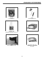
1
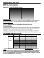
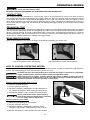
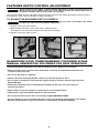
651 SERIES
PNEUMATIC STAPLER
ENGRAPADORA NEUMÁTICA
AGRAFEUSE
OPERATION and MAINTENANCE MANUAL
MANUAL DE OPERACIÓN Y DE MANTENIMIENTO
MANUEL D’INSTRUCTIONS ET D’ENTRETIEN
BEFORE OPERATING THIS TOOL, ALL OPERATORS SHOULD STUDY THIS MANUAL TO
UNDERSTAND AND FOLLOW THE SAFETY WARNINGS AND INSTRUCTIONS. KEEP THESE
INSTRUCTIONS WITH THE TOOL FOR FUTURE REFERENCE. IF YOU HAVE ANY QUESTIONS,
CONTACT YOUR BOSTITCH REPRESENTATIVE OR DISTRIBUTOR.
ANTES DE OPERAR ESTA HERRAMIENTA, TODOS LOS OPERADORES DEBERÁN ESTUDIAR
ESTE MANUAL PARA PODER COMPRENDER Y SEGUIR LAS ADVERTENCIAS SOBRE
SEGURIDAD Y LAS INSTRUCCIONES. MANTENGA ESTAS INSTRUCCIONES CON LA
HERRAMIENTA PARA FUTURA REFERENCIA, SI TIENE ALGUNA DUDA, COMUNÍQUESE CON
SU REPRESENTANTE DE BOSTITCH O CON SU DISTRIBUIDOR.
LIRE ATTENTIVEMENT LE PRÉSENT MANUEL AVANT D’UTILISER L’APPAREIL. PRÉTER UNE
ATTENTION TOUTE PARTICULIÈRE AUX CONSIGNES DE SÉCURITÉ ET AUX
AVERTISSEMENTS. GARDER CE MANUEL AVEC L’OUTIL POUR FUTUR RÉFÉRENCE. SI VOUS
AVEZ DES QUESTIONS, CONTACTEZ VOTRE REPRÉSENTANT OU VOTRE CONCESSIONNAIRE
BOSTITCH.
189863RA 04/10
STANLEY FASTENING SYSTEMS L.P.
INTRODUCTION
Bostitch pneumatic tools are precision-built, and designed for high speed/high volume fastening. These tools will
deliver efficient, dependable service when used correctly and with care. As with any fine power tool, for best
performance the manufacturer’s instructions must be followed. Please study this manual before operating the tool
and understand the safety warnings and cautions. The instructions on installation, operation and maintenance
should be read carefully, and the manuals kept for reference. NOTE: Additional safety measures may be required
because of your particular application of the tool. Contact your Bostitch representative or distributor with any
questions concerning the tool and its use. Bostitch, Inc., East Greenwich, Rhode Island 02818.
INDEX
Safety Instructions . . . . . . . . . . . . . . . . . . . . . . . . . . . . . . . . . . . . . . . . . . . . 3-4
Tool/Fastener Specifications . . . . . . . . . . . . . . . . . . . . . . . . . . . . . . . . . . . . . . 4
Operating Modes . . . . . . . . . . . . . . . . . . . . . . . . . . . . . . . . . . . . . . . . . . . . . . . 5
Air Supply and Connections. . . . . . . . . . . . . . . . . . . . . . . . . . . . . . . . . . . . . . . 6
Depth Control Adjustment . . . . . . . . . . . . . . . . . . . . . . . . . . . . . . . . . . . . . . . . 8
Tool Operation. . . . . . . . . . . . . . . . . . . . . . . . . . . . . . . . . . . . . . . . . . . . . . . 9-10
Jam Clearing Procedure . . . . . . . . . . . . . . . . . . . . . . . . . . . . . . . . . . . . . . . 10
Tool Operation Check. . . . . . . . . . . . . . . . . . . . . . . . . . . . . . . . . . . . . . . . . . . 11
Maintaining the Pneumatic Tool . . . . . . . . . . . . . . . . . . . . . . . . . . . . . . . . . . 11
Troubleshooting . . . . . . . . . . . . . . . . . . . . . . . . . . . . . . . . . . . . . . . . . . . . . . 12
Available Accessories . . . . . . . . . . . . . . . . . . . . . . . . . . . . . . . . . . . . . . . . . . 13
NOTE:
Bostitch tools have been engineered to provide excellent customer satisfaction and are designed to achieve
maximum performance when used with precision Bostitch fasteners engineered to the same exacting
standards. Bostitch cannot assume responsibility for product performance if our tools are used with
fasteners or accessories not meeting the specific requirements established for genuine Bostitch nails,
staples and accessories.
™
®
LIMITED WARRANTY — U.S. and Canada Only
Stanley Fastening Systems L.P. (“Bostitch”) warrants to the original retail purchaser that the product purchased is free
from defects in material and workmanship, and agrees to repair or replace, at Bostitch’s option, any defective Bostitch
branded pneumatic stapler or nailer for a period of seven (7) years from date of purchase (one (1) year from the date
of purchase for compressors and tools used in production applications). Warranty is not transferable. Proof of purchase
date required. This warranty covers only damage resulting from defects in material or workmanship; it does not cover
conditions or malfunctions resulting from normal wear, neglect, abuse, accident or repairs attempted or made by other
than our national repair center or authorized warranty service centers. Driver blades, bumpers, o-rings, pistons and
piston rings are considered normally wearing parts. For optimal performance of your Bostitch tool always use genuine
Bostitch fasteners and replacement parts.
THIS WARRANTY IS IN LIEU OF ALL OTHER WARRANTIES, EXPRESS OR IMPLIED, INCLUDING BUT NOT
LIMITED TO THE IMPLIED WARRANTIES OF MERCHANTABILITY OR FITNESS FOR A PARTICULAR PURPOSE.
BOSTITCH SHALL NOT BE LIABLE FOR ANY INCIDENTAL OR CONSEQUENTIAL DAMAGES.
Some states and countries do not allow limitations on how long an implied warranty lasts, or the exclusion or limitation
of incidental or consequential damages, so the above limitations or exclusions may not apply to you. This warranty
gives you specific legal rights, and you may also have other rights which vary from state to state and country to country.
To obtain warranty service in the U.S. return the product, together with proof of purchase, to the U.S. Bostitch National
or Regional Independent Authorized Warranty Service Center. In the U.S. you may call us at 1-800-556-6696 or visit
www.BOSTITCH.com for the location most convenient for you. In Canada please call us at 800-567-7705 or visit
www.BOSTITCH.com
-2-
SAFETY INSTRUCTIONS
EYE PROTECTION which conforms to ANSI specifications and provides protection against
flying particles both from the FRONT and SIDE should ALWAYS be worn by the operator and
others in the work area when connecting to air supply, loading, operating or servicing this
tool. Eye protection is required to guard against flying fasteners and debris, which could
cause severe eye injury.
The employer and/or user must ensure that proper eye protection is worn. Eye protection
equipment must conform to the requirements of the American National Standards Institute,
ANSI Z87.1 and provide both frontal and side protection. NOTE: Non-side shielded
spectacles and face shields alone do not provide adequate protection.
CAUTION: Additional Safety Protection will be required in some environments. For
example, the working area may include exposure to noise level which can lead to hearing
damage. The employer and user must ensure that any necessary hearing protection is
provided and used by the operator and others in the work area. Some environments will
require the use of head protection equipment. When required, the employer and user must
ensure that head protection conforming to ANSI Z89.1 is used.
AIR SUPPLY AND CONNECTIONS
Do not use oxygen, combustible gases, or bottled gases as a power source for this tool as
tool may explode, possibly causing injury.
Do not use supply sources which can potentially exceed 200 P.S.I.G. as tool may burst,
possibly causing injury.
The connector on the tool must not hold pressure when air supply is disconnected. If a
wrong fitting is used, the tool can remain charged with air after disconnecting and thus will
be able to drive a fastener even after the air line is disconnected possibly causing injury.
Do not pull trigger or depress contact arm while connected to the air supply as the tool may
cycle, possibly causing injury.
Always disconnect air supply: 1.) Before making adjustments; 2.) When servicing the tool;
3.) When clearing a jam; 4.) When tool is not in use; 5.) When moving to a different work area,
as accidental actuation may occur, possibly causing injury.
LOADING TOOL
When loading tool: 1.) Never place a hand or any part of body in fastener discharge area of
tool; 2.) Never point tool at anyone; 3.) Do not pull the trigger or depress the trip as
accidental actuation may occur, possibly causing injury.
OPERATION
Always handle the tool with care: 1.) Never engage in horseplay; 2.) Never pull the trigger
unless nose is directed toward the work; 3.) Keep others a safe distance from the tool while
tool is in operation as accidental actuation may occur, possibly causing injury.
The operator must not hold the trigger pulled on contact arm tools except during fastening
operation as serious injury could result if the trip accidentally contacted someone or
something, causing the tool to cycle.
Keep hands and body away from the discharge area of the tool. A contact arm tool may
bounce from the recoil of driving a fastener and an unwanted second fastener may be driven
possibly causing injury.
Check operation of the contact arm mechanism frequently. Do not use the tool if the arm
is not working correctly as accidental driving of a fastener may result. Do not interfere with
the proper operation of the contact arm mechanism.
Do not drive fasteners on top of other fasteners or with the tool at an overly steep angle as
this may cause deflection of fasteners which could cause injury.
Do not drive fasteners close to the edge of the work piece as the wood may split, allowing
the fastener to be deflected possibly causing injury.
This nailer produces SPARKS during operation. NEVER use the nailer near flammable substances,
gases or vapors including lacquer, paint, benzine, thinner, gasoline, adhesives, mastics, glues or
any other material that is -- or the vapors, fumes or by-products of which are -- flammable,
combustible or explosive. Using the nailer in any such environment could cause an EXPLOSION
resulting in personal injury or death to user and bystanders.
Never use utility hook to hang tool from body, clothing or belt.
Always verify and be aware of tool operating mode by inspecting the trigger before connecting
to an air supply and/or using the tool.
Be aware that once the mode locking pin is removed, the trigger is converted to a selectable
trigger, enabling both contact trip and sequential trip operating modes.
-3-
MAINTAINING THE TOOL
When working on air tools note the warnings in this manual and use extra care when
evaluating problem tools.
TOOL SPECIFICATIONS
All dimensions in inches unless otherwise specified.
651S5
7/16” Crown Stapler
70-120 PSI (4.9 to 8.43kg/cm2)
16S5 & 17S5 Series Staples
16 & 17 Gauge
1” to 2” (25mm to 50mm)
120
14”
Description
Operation Pressure Range
Fastener Type
Fastener Gauge
Fastener Range
Magazine Capacity
Length
Width
Height
Weight
3 1/8”
11”
4.3 lbs.
Tool Air Fitting:
This tool uses a free-flow connector plug, 1/4” N.P.T. The minimum inside diameter should be .200” (5mm).
The fitting must be capable of discharging tool air pressure when disconnected from the air supply.
Operating Pressure:
70 to 120 p.s.i.g. (4.9 to 8.43 kg/cm2). Select the operating pressure within in this range for best fastener
performance. DO NOT EXCEED THIS RECOMMENDED OPERATING PRESSURE.
Air Consumption:
The 651 Series staplers require 5.3 cubic feet per minute or C.F.M. (150 liters per minute or LT/MIN) of free
air at 80PSI (5.6 kg/cm2) to operate at a rate of 100 fasteners per minute. To determine the appropriately
sized air compressor, take the actual rate at which the tool will be run and compare the required C.F.M.
(LT/MIN) to the compressors free air delivery (C.F.M./ LT/MIN) at 80 PSI (5.6 kg/cm2).
For example, if your fastener usage averages 50 fasteners per minute, you need 50% of the tools C.F.M.
required to operate the tool at the rate of 100 fasteners per minute. In this case, be sure that your air
compressor can deliver a minimum of 2.7 C.F.M. (75 LT/MIN) at 80 PSI(5.6 kg/cm2) for optimum performance.
FASTENER SPECIFICATIONS
Tool Model
651S5-1
Fastener SKU
Gauge
Crown Width
Length
16S5-35
16S5-38
16S5-44
16S5-44GAL
16S5-50
16S5-50GAL
17S5-25G
17S5-28G
17S5-31G
17S5-34G
17S5-38G
17S5-41G
17S5-44G
17S5-50G
16
16
16
16
16
16
17
17
17
17
17
17
17
17
7/16”
7/16”
7/16”
7/16”
7/16”
7/16”
7/16”
7/16”
7/16”
7/16”
7/16”
7/16”
7/16”
7/16”
1-3/8” (35mm)
1-1/2” (38mm)
1-3/4” (44mm)
1-3/4” (44mm)
2” (50mm)
2” (50mm)
1” (25mm)
1-1/8” (28mm)
1-1/4” (31mm)
1-3/8” (34mm)
1-1/2” (38mm)
1-5/8” (41mm)
1-3/4” (44mm)
2” (50mm)
* Stainless steel fasteners also available in certain sizes. Visit www.BOSTITCH.com for further details.
NOTE:
BOSTITCH tools have been engineered to provide superior customer satisfaction and are
designed to achieve maximum performance when used with precision BOSTITCH fasteners engineered to
the same exacting standards. BOSTITCH cannot assume responsibility for product performance if
our tools are used with fasteners or accessories not meeting the specific requirements established
for genuine BOSTITCH fasteners and accessories.
-4-
OPERATING MODES
Always disconnect air supply before making adjustments as accidental actuation may
occur, possibly causing injury.
BOSTITCH OFFERS TWO MODES OF OPERATION FOR THIS SERIES TOOL.
CONTACT TRIP:
The common operation procedure on “Contact Trip” tools is for the operator to contact the work surface to
actuate the trip mechanism while keeping the trigger pulled, thus driving a fastener each time the work surface
is contacted. This will allow rapid fastener placement on many jobs. All pneumatic tools are subject to recoil
when driving fasteners. The tool may bounce, releasing the trip, and if unintentionally allowed to re-contact the
work surface with the trigger still actuated (finger still holding the trigger pulled) an unwanted second fastener
will be driven.
SEQUENTIAL TRIP:
The Sequential Trip requires the operator to hold the tool against the work before pulling the trigger. This makes
accurate fastener placement easier. The Sequential Trip allows exact fastener location without the possibility if
driving a second fastener on recoil as described under “Contact Trip”. The Sequential Trip Tool has a positive
advantage because it will not accidentally drive a fastener if the tool is contacted against the work surface - or
anything else - while the operator is holding the trigger pulled.
MODE IDENTIFICATION:
Refer to Tool Operation Instructions on pages 9-10 before proceeding to use this tool.
Sequential Trip Mode
(trip mode selector switch pointing down)
Contact Trip Mode
(trip mode selector switch pointing up)
HOW TO CHANGE OPERATING MODES:
The 651 stapler is initially locked in the sequential trip operating mode. In order to enable the mode selection
feature, the mode locking pin must be removed as shown in FIG A.
Be aware that once the mode locking pin is removed, the trigger is converted to a selectable
trigger, enabling either sequential trip or contact trip operating modes.
Always disconnect air supply: 1) Before making adjustments; 2) When servicing the tool; 3)
When clearing a jam; 4) When tool is not in use; 5) When moving to a different work area, as
accidental actuation may occur, possibly causing injury.
Selecting Contact Trip Mode: Refer to Fig A.
1) Remove mode locking pin.
2) Push in pivot pin and hold.
pivot
pin
3) Rotate the selector 180 degrees counter-clockwise to
the contact trip position, while pushing in the pivot pin.
4) Ensure the selector is fully seated in the new position.
Always verify and be aware of tool operating
mode by inspecting the trigger before connecting
to an air supply and/or using the tool.
locking
pin
trip selector
Selecting Sequential Trip Mode:
1) Remove mode locking pin (if installed).
2) Push in pivot pin and hold.
FIG A
3) Rotate the selector 180 degrees clockwise to the
sequential trip position, while pushing in the pivot pin.
4) Ensure the selector is fully seated in the new position.
-5-
AIR SUPPLY AND CONNECTIONS
Do not use oxygen, combustible gases, or bottled gases as a power source for this tool as
tool may explode, possibly causing injury.
FITTINGS:
Install a male plug on the tool which is free flowing and which will release air pressure from the tool when
disconnected from the supply source.
HOSES:
Air hoses should have a minimum of 150 p.s.i. (10.6 kg/cm2) working pressure rating or 150 percent of the
maximum pressure that could be produced in the air system. The supply hose should contain a fitting that will
provide “quick disconnecting” from the male plug on the tool.
SUPPLY SOURCE:
Use only clean regulated compressed air as a power source for this tool. NEVER USE OXYGEN, COMBUSTIBLE
GASES, OR BOTTLED GASES, AS A POWER SOURCE FOR THIS TOOL AS TOOL MAY EXPLODE.
REGULATOR:
A pressure regulator with an operating pressure of 0 - 125 p.s.i. (0 - 8.79 kg/cm2) is required to control the
operating pressure for safe operation of this tool. Do not connect this tool to air pressure which can potentially
exceed 200 p.s.i. (14 kg/cm2) as tool may fracture or burst, possibly causing injury.
OPERATING PRESSURE:
Do not exceed recommended maximum operating pressure as tool wear will be greatly increased. The air
supply must be capable of maintaining the operating pressure at the tool. Pressure drops in the air supply can
reduce the tool’s driving power. Refer to “TOOL SPECIFICATIONS” for setting the correct operating pressure
for the tool.
FILTER:
Dirt and water in the air supply are major causes of wear in pneumatic tools. A filter will help to get the best
performance and minimum wear from the tool. The filter must have adequate flow capacity for the specific
installation. The filter has to be kept clean to be effective in providing clean compressed air to the tool. Consult
the manufacturer’s instructions on proper maintenance of your filter. A dirty and clogged filter will cause a
pressure drop which will reduce the tool’s performance.
LUBRICATION
Frequent, but not excessive, lubrication is required for best performance. Use BOSTITCH Air Tool Lubricant, Mobil
Velocite #10, or equivalent. Do not use detergent oil or additives as these lubricants will cause accelerated wear to the
seals and bumpers in the tool, resulting in poor tool performance and frequent tool maintenance. Only a few drops of
oil at a time is necessary. Too much oil will only collect inside the tool and will be noticeable in the exhaust cycle.
COLD WEATHER OPERATION:
For cold weather operation, near and below freezing, the moisture in the air line may freeze and prevent tool operation.
We recommend the use of BOSTITCH winter formula air tool lubricant or permanent antifreeze (ethylene glycol) as a
cold weather lubricant.
CAUTION: Do not store tools in a cold weather environment to prevent frost or ice formation on the
tools operating valves and mechanisms that could cause tool failure.
NOTE: Some commercial air line drying liquids are harmful to “O”-rings and seals – do not use these
low temperature air dryers without checking compatibility.
-6-
LOADING THE 651 STAPLER
EYE PROTECTION which conforms to ANSI specifications and provides protection against
flying particles both from the FRONT and SIDE should ALWAYS be worn by the operator and
others in the work area when connecting to air supply, loading, operating or servicing this
tool. Eye protection is required to guard against flying fasteners and debris, which could
cause severe eye injury.
The employer and/or user must ensure that proper eye protection is worn. Eye protection
equipment must conform to the requirements of the American National Standards Institute,
ANSI Z87.1 and provide both frontal and side protection. NOTE: Non-side shielded
spectacles and face shields alone do not provide adequate protection.
TO PREVENT ACCIDENTAL INJURIES:
• Never place a hand or any other part of the body in nail discharge area of tool while
the air supply is connected.
• Never point the tool at anyone else.
• Never engage in horseplay.
• Never pull the trigger unless nose is directed at the work.
• Always handle the tool with care.
• Do not pull the trigger or depress the trip mechanism while loading the tool.
LOADING THE 651 SERIES STAPLERS:
1. Move pusher to rear until latched. Cover will open. Pusher will be held in place by a pin detent.
2. Drop staples over magazine and slide forward. Repeat until magazine is loaded.
3. Pull Pusher back slightly and depress pin detents. Allow pusher to slide forward over the pin detent.
-7-
FASTENER DEPTH CONTROL ADJUSTMENT
Always disconnect air supply: 1) Before making adjustments; 2) When servicing the tool; 3)
When clearing a jam; 4) When tool is not in use; 5) When moving to a different work area, as
accidental actuation may occur, possibly causing injury.
The Fastener Depth Control Adjustment feature provides control of the staple drive depth from flush with or
just above the work surface to shallow or deep countersink.
TO ADJUST THE FASTENER DEPTH CONTROL:
Disconnect tool from air supply before attempting any parts disassembly and before
changing the work contacting element adjustment.
1) Loosen screw with 4mm hex key.
2) Move sliding shoe down (away from nose) to decrease the
drive depth or up (toward the nose) to increase the drive depth.
3) Tighten screw with 4mm hex key
IN ADDITION TO THE OTHER WARNINGS CONTAINED IN THIS
MANUAL OBSERVE THE FOLLOWING FOR SAFE OPERATION
• Use the BOSTITCH pneumatic tool only for the purpose for which it was designed.
• Never use this tool in a manner that could cause a fastener to be directed toward the user
or others in the work area.
• Do not use the tool as a hammer.
• Always carry the tool by the handle. Never carry the tool by the air hose.
• Do not alter or modify this tool from the original design or function without approval from
BOSTITCH, INC.
• Always be aware that misuse and improper handling of this tool can cause injury to
yourself and others.
• Never clamp or tape the trigger or contact trip in an actuated position.
• Never leave a tool unattended with the air hose attached.
• Do not operate this tool if it does not contain a legible WARNING LABEL.
• Do not continue to use a tool that leaks air or does not function properly. Notify your nearest
Bostitch representative if your tool continues to experience functional problems.
-8-
TOOL OPERATION
EYE PROTECTION which conforms to ANSI specifications and provides protection against
flying particles both from the FRONT and SIDE should ALWAYS be worn by the operator and
others in the work area when connecting to air supply, loading, operating or servicing this
tool. Eye protection is required to guard against flying fasteners and debris, which could
cause severe eye injury.
The employer and/or user must ensure that proper eye protection is worn. Eye protection
equipment must conform to the requirements of the American National Standards Institute,
ANSI Z87.1 and provide both frontal and side protection. NOTE: Non-side shielded
spectacles and face shields alone do not provide adequate protection.
BEFORE HANDLING OR OPERATING THIS TOOL:
I.
READ AND UNDERSTAND THE WARNINGS CONTAINED IN THIS MANUAL.
II. REFER TO “TOOL SPECIFICATIONS” IN THIS MANUAL TO IDENTIFY THE
OPERATING SYSTEM ON YOUR TOOL.
There are two available operation modes on these BOSTITCH pneumatic tools. They are:
1. SEQUENTIAL TRIP OPERATION 2. CONTACT TRIP OPERATION
OPERATION
BOSTITCH offers two types of operating modes which function differently: Sequential Trip and Contact Trip.
Each mode has specific advantages. You should evaluate your particular construction project to determine
which mode is best.
Your tool was shipped from the factory in the Sequential Trip configuration. It can easily be converted to the
Contact Trip mode of operation using this Contact Trip conversion kit. Refer to “How to Change Operator Modes”
to change between Sequential Trip and Contact Trip modes.
Always verify and be aware of tool operating mode by inspecting the trigger before connecting to
an air supply and/or using the tool.
1. SEQUENTIAL TRIP OPERATION:
The Sequential Trip (Mode) gets its name from the “sequence” required to drive a fastener. To drive a fastener,
the operator must first depress the “trip” FULLY against the work surface and then pull the trigger. To drive a
second nail, the operator must lift the tool from the work surface, release the trigger and then repeat the above
sequence.
1. The Sequential Trip (Mode): offers a positive safety advantage since it will not
accidentally drive a fastener if the tool is bumped against any surface or anybody while
the operator is holding the tools with the trigger pulled.
2. The Sequential Trip (Mode): allows “place nailing” without the possibility of driving a
second, unwanted fastener on recoil as described below under “Contact Trip”.
2. CONTACT TRIP OPERATION:
Be aware that once the mode locking pin is removed, the trigger is converted to a selectable
trigger, enabling both contact trip and sequential trip operating modes.
Your new BOSTITCH tool can be configured for use in Contact Trip “Conventional trip” mode. To drive a nail,
the “trip” and the trigger must both be depressed. In conventional Contact Trip tools, the trigger may be
depressed and held, and each “contact” between the trip and the work surface will drive a nail.
A. SINGLE FASTENER PLACEMENT (Place Nailing) -- First position the “trip” FULLY
on the work surface, WITHOUT PULLING THE TRIGGER. Depress the “trip” FULLY until
the nose of the tool touches the work surface and then pull the trigger to drive a nail. Do
not press the tool against the work surface with extra force. Instead, allow the tool to recoil
off the work surface to avoid a second unwanted fastener. Note: remove your finger from
the trigger after each operation.
B. RAPID FIRE OPERATION (“Bump” Nailing) – First, hold the tool with the “trip”
pointing towards but not touching the work surface. Pull the trigger and then tap or “bump”
the trip against the work surface using a bouncing motion. Each depression of the “trip”
will cause a nail to be driven.
-9-
TOOL OPERATION (CONTINUED)
The Contact Trip will not prevent a nail from being accidentally driven if the trigger is
depressed and the “trip” is bumped against any object or person. Never hold or carry the
tool with your finger on the trigger. Only depress and hold trigger when you intend to rapidly
drive multiple nails and the tool is pointed at the work surface.
When using conventional Contact Trip for Place Nailing, the tool may bounce due to recoil,
and if the tool is allowed to re-contact the work surface while you are holding the trigger
pulled, a second unwanted nail will be driven. You should allow the tool to recoil far enough
to release the trip and avoid a second cycle. Don’t push the tool down extra hard; let the
tool do the work.
The operator must not hold the trigger pulled on contact trip tools except during fastening
operation, as serious injury could result if the trip accidentally contacted someone or
something, causing the tool to cycle.
Keep hands and body away from the discharge area of the tool. A contact trip tool may
bounce from the recoil of driving a fastener and an unwanted second fastener may be
driven, possibly causing injury.
Never use rafter hook to hang tool from body, clothing or belt.
JAM CLEARING PROCEDURE
Disconnect tool from air supply before clearing a jam, making adjustments or before
attempting any part assembly or disassembly.
On occasion staples can jam in the nose of a pneumatic stapler. This can be caused by striking a metal
plate in the wall, drywall screw, or some other hard object. The 651 Series staplers feature open drive
channel architecture for jam clearing. To clear a jam follow this procedure:
1) Disconnect the tool from the air supply.
2) Release the pusher so it is no longer applying force to the staples.
3) Open the jam clearing nose door by pulling down and then up on the latch.
4) Remove the jammed fastener. In certain circumstances, pliers may be required to remove the fastener.
5) Close the jam clearing nose door latch.
6) Release nail pusher back behind staples.
-10-
TOOL OPERATION CHECK
CAUTION: Remove all fasteners from tool before performing tool operation check.
1. CONTACT TRIP OPERATION:
A. With finger off the trigger, press the contact trip against the work surface.
THE TOOL MUST NOT CYCLE.
B. Hold the tool off the work surface, and pull the trigger.
THE TOOL MUST NOT CYCLE.
C. With the tool off the work surface, pull the trigger. Press the contact trip against the work surface.
THE TOOL MUST CYCLE.
D. Without touching the trigger, press the contact trip against the work surface,
then pull the trigger.
THE TOOL MUST CYCLE.
2. SEQUENTIAL TRIP OPERATION:
A. Press the contact trip against the work surface, without touching the trigger.
THE TOOL MUST NOT CYCLE.
B. Hold the tool off the work surface and pull the trigger.
THE TOOL MUST NOT CYCLE.
Release the trigger. The trigger must return to the trigger stop on the frame.
C. Pull the trigger and press the contact trip against the work surface.
THE TOOL MUST NOT CYCLE.
D. With finger off the trigger, press the contact trip against the work surface. Pull the trigger.
THE TOOL MUST CYCLE.
MAINTAINING THE PNEUMATIC TOOL
When working on air tools, note the warnings in this manual and use extra care evaluating
problem tools.
CAUTION: Pusher spring (constant force spring). Caution must be used when working with the spring
assembly. The spring is wrapped around, but not attached to, a roller. If the spring is extended beyond
its length, the end will come off the roller and the spring will roll up with a snap, with a chance of
pinching your hand. Also the edges of the spring are very thin and could cut. Care must also be taken
to insure no permanent kinks are put in the spring as this will reduce the springs force.
REPLACEMENT PARTS:
Use only genuine BOSTITCH replacement parts. Do not use modified parts.
ASSEMBLY PROCEDURE FOR SEALS:
When repairing a tool, make sure the internal parts are clean and lubricated. Use Parker “O”-LUBE,
Magnalube, or equivalent on all “O”-rings. Coat each “O”-ring with lubricant before assembling.
AIR SUPPLY-PRESSURE AND VOLUME:
Air volume is as important as air pressure. The air volume supplied to the tool may be inadequate because of
undersize fittings and hoses, or from the effects of dirt and water in the system. Restricted air flow will prevent
the tool from receiving an adequate volume of air, even though the pressure reading is high. The results will be
slow operation, misfeeds or reduced driving power. Before evaluating tool problems for these symptoms, trace
the air supply from the tool to the supply source for restrictive connectors, low points containing water and
anything else that would prevent full volume flow of air to the tool.
-11-
TROUBLE SHOOTING
PROBLEM
CAUSE
Trigger valve housing l eaks air
O-ring cut or cracked . . . . . . . . . . . . . . . . . . . . .Replace O-ring
CORRECTION
Trigger valve stem leaks air
O-ring/seals cut or cracked . . . . . . . . . . . . . . . . .Replace trigger valve assembly
Frame/nose leaks air
Loose nose screws . . . . . . . . . . . . . . . . . . . . . . .Tighten and recheck
O-ring or Gasket is cut or cracked . . . . . . . . . . .Replace O-ring or gasket
Bumper cracked/worn . . . . . . . . . . . . . . . . . . . . .Replace bumper
Frame/cap l eaks ai r
Damaged gasket or seal . . . . . . . . . . . . . . . . . .Replace gasket or seal
Cracked/worn head valve bumper . . . . . . . . . . .Replace bumper
Loose cap screws . . . . . . . . . . . . . . . . . . . . . . . .Tighten and recheck
Failure to cycle
Air supply restriction . . . . . . . . . . . . . . . . . . . . . .Check air supply equipment
Tool dry, lack of lubrication . . . . . . . . . . . . . . . . .Use BOSTITCH Air Tool Lubricant
Worn head valve O-rings . . . . . . . . . . . . . . . . . .Replace O-rings
Broken cylinder cap spring . . . . . . . . . . . . . . . . .Replace cylinder cap spring
Head valve stuck in cap . . . . . . . . . . . . . . . . . . .Disassemble/Check/Lubricate
Lack of power; slow t o cycl e
Tool dry, lacks lubrication . . . . . . . . . . . . . . . . . .Use BOSTITCH Air Tool Lubricant
Broken cylinder cap spring . . . . . . . . . . . . . . . . .Replace cap spring
O-rings/seals cut or cracked . . . . . . . . . . . . . . . .Replace O-rings/seals
Exhaust blocked . . . . . . . . . . . . . . . . . . . . . . . .Check bumper, head valve spring, muffler
Trigger assembly worn/leaks . . . . . . . . . . . . . . .Replace trigger assembly
Dirt/tar build up on driver . . . . . . . . . . . . . . . . . .Disassemble nose/driver to clean
Cylinder sleeve not seated correctly
on bottom bumper . . . . . . . . . . . . . . . . . . . . . . .Disassemble to correct
Head valve dry . . . . . . . . . . . . . . . . . . . . . . . . . .Disassemble/lubricate
Air pressure too low . . . . . . . . . . . . . . . . . . . . . .Check air supply equipment
Skippi ng fasteners; intermittent feed
Worn bumper . . . . . . . . . . . . . . . . . . . . . . . . . . .Replace bumper
Tar/dirt in driver channel . . . . . . . . . . . . . . . . . . .Disassemble and clean nose and driver
Air restriction/inadequate air flow through
quick disconnect socket and plug . . . . . . . . . . . .Replace quick disconnect fittings
Worn piston O-ring . . . . . . . . . . . . . . . . . . . . . . .Replace O-ring, check driver
Tool dry, lacks lubrication . . . . . . . . . . . . . . . . . .Use BOSTITCH Air Tool Lubricant
Damaged pusher spring . . . . . . . . . . . . . . . . . . .Replace spring
Low air pressure . . . . . . . . . . . . . . . . . . . . . . . . .Check air supply system to tool
Loose magazine nose screws . . . . . . . . . . . . . .Tighten all screws
Fasteners too short for tool . . . . . . . . . . . . . . . .Use only recommended fasteners
Bent fasteners . . . . . . . . . . . . . . . . . . . . . . . . . .Discontinue using these fasteners
Wrong size fasteners . . . . . . . . . . . . . . . . . . . . .Use only recommended fasteners
Leaking head cap gasket . . . . . . . . . . . . . . . . . .Tighten screws/replace gasket
Trigger valve O-ring cut/worn . . . . . . . . . . . . . . .Replace O-ring
Broken/chipped driver . . . . . . . . . . . . . . . . . . . . .Replace driver (check piston O-ring)
Dry/dirty magazine . . . . . . . . . . . . . . . . . . . . . . .Clean/lubricate use BOSTITCH Air Tool Lubricant
Worn magazine . . . . . . . . . . . . . . . . . . . . . . . . .Replace magazine
Fast eners jam in t ool
Driver channel worn . . . . . . . . . . . . . . . . . . . . . .Replace nose/check door
Wrong size fasteners . . . . . . . . . . . . . . . . . . . . .Use only recommended fasteners
Bent fasteners . . . . . . . . . . . . . . . . . . . . . . . . . .Discontinue using these fasteners
Loose magazine/nose screws . . . . . . . . . . . . . .Tighten all screws
Broken/chipped driver . . . . . . . . . . . . . . . . . . . . .Replace driver
-12-
AVAILABLE ACCESSORIES
651-RB1
651 O-RING KIT
TVA6
TRIGGER VALVE KIT
PREMOIL-4OZ
PREMIUM PNEUMATIC TOOL OIL
16S5 SERIES STAPLES
VSA5
VINYL SIDING ADAPTER
PRO-3850 & PRO-1450
PREMIUM POLYURETHANE
AIR HOSE
-13-